
1.6 TDI CR engine (EA189) · Cylinder head, valve gear · Cylinder head
Removing and installing cylinder head cover
⇒ 1.1.1 Schematic overview - fuel system, Polo
⇒ 1.4.1 Removing and installing injector seal in cylinder head cover
Special tools and workshop equipment required
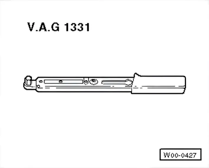
- Torque wrench - V.A.G 1331-
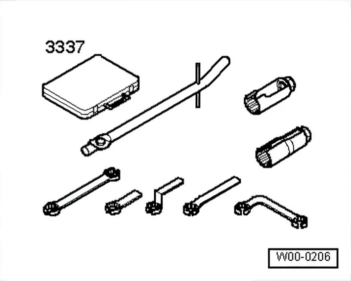
- Lambda probe open ring spanner set - 3337-
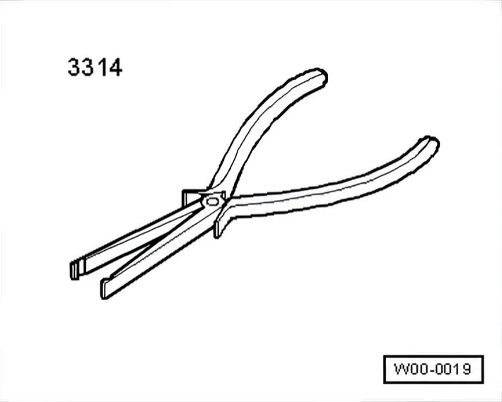
- Pliers - 3314-
Removing
- Remove engine cover panel ⇒ 3 Engine cover panel.
- Remove noise insulation at injectors.
- Remove injectors ⇒ 3.5 Removing and installing injectors.
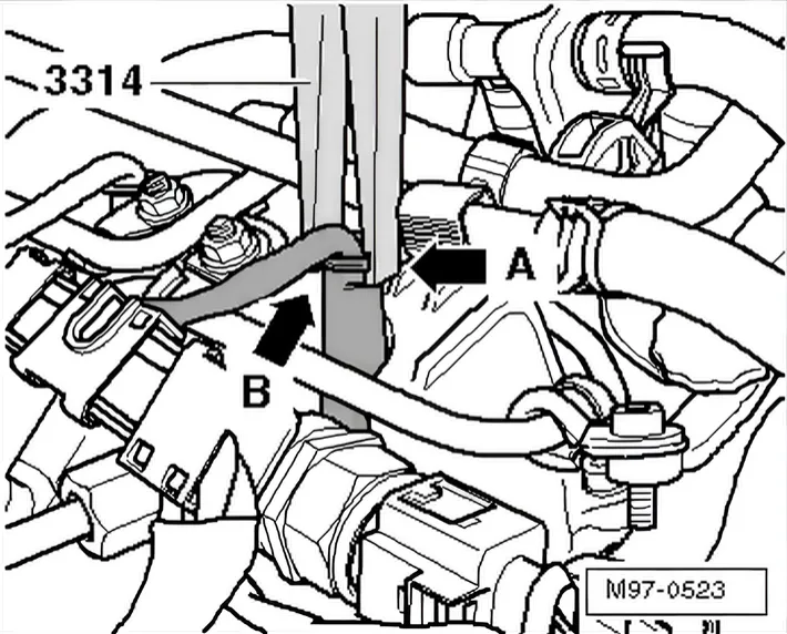
- Position pliers - 3314- with groove -arrow A- on support sleeve shoulder -arrow B-.
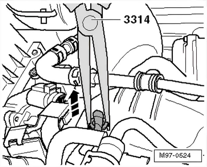
- Carefully pull connector off glow plug in direction of -arrow-.
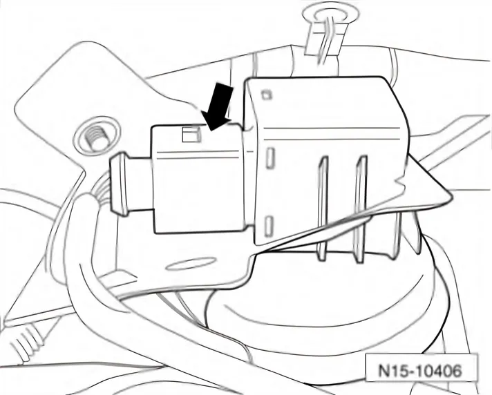
- Pull connector of position sender for charge pressure positioner - G581- -arrow- off turbocharger and guide wiring out of retainers.
Polo
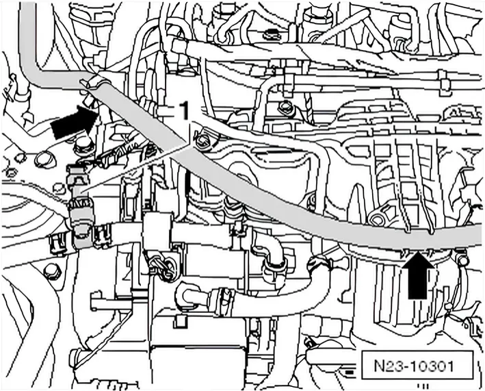
- Unclip coolant return hose -arrows- and place coolant line to one side.
The installation position of the coolant return hose can vary.
Continued for all vehicles
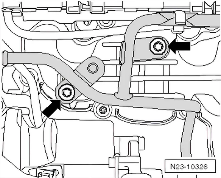
- Unscrew the securing bolts on the intake manifold -arrowsand move the coolant return line to the side.
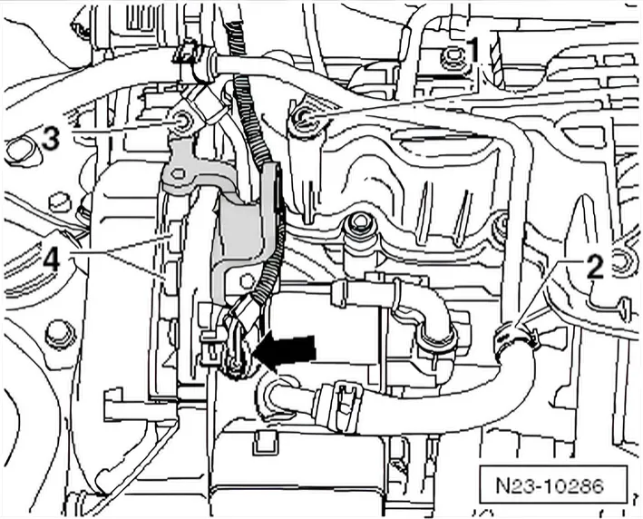
- Unscrew bolts -3- + -4-, remove lifting eye.
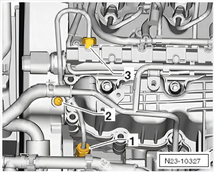
- Remove high-pressure line between high-pressure pump -1- and fuel rail -3-.
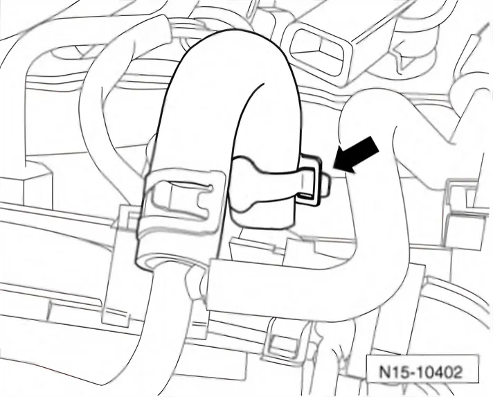
- Open clamp -arrow- and pull line off fuel rail.
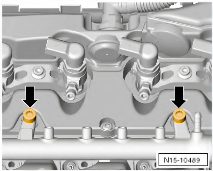
- Unscrew bolts -arrows-.
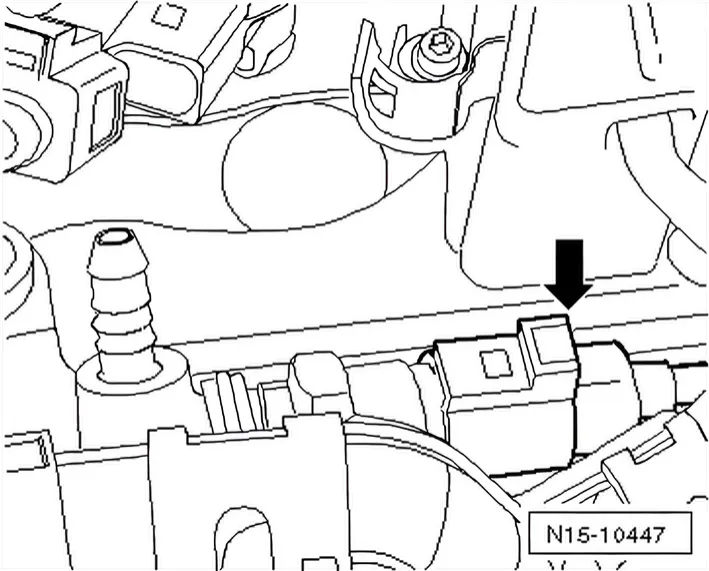
- Pull connector off fuel pressure regulating valve - N 276- -arrow-.
- Remove wiring harness from fuel rail and place wiring harness to one side.
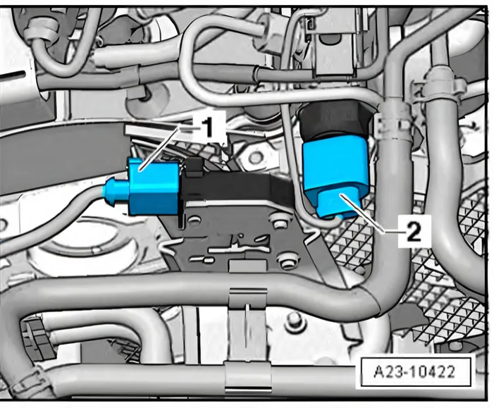
- Remove the connector on the fuel pressure sender - G 247- -2-.
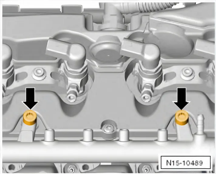
- Remove high pressure accumulator.
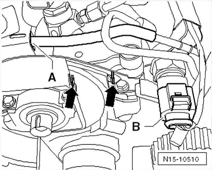
- Pull vacuum line off cylinder head cover -arrow A-.
- Remove remaining vacuum hoses from bracket on cylinder head cover.
- Remove remaining electric cables/wires.
- Remove upper toothed belt guard.
- Remove breather line between cylinder head cover and intake hose. Press quick-release fasteners to do this.
- Remove securing bolts from cylinder head cover.
- Remove cylinder head cover.
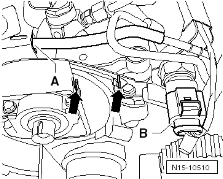
- Unclip the cylinder head cover at the locking lugs -arrows- on the rear toothed belt guard.
Install in reverse order of removal. During this procedure, observe the following:
- Screw on cylinder head cover hand-tight in the sequence 1 … 6.
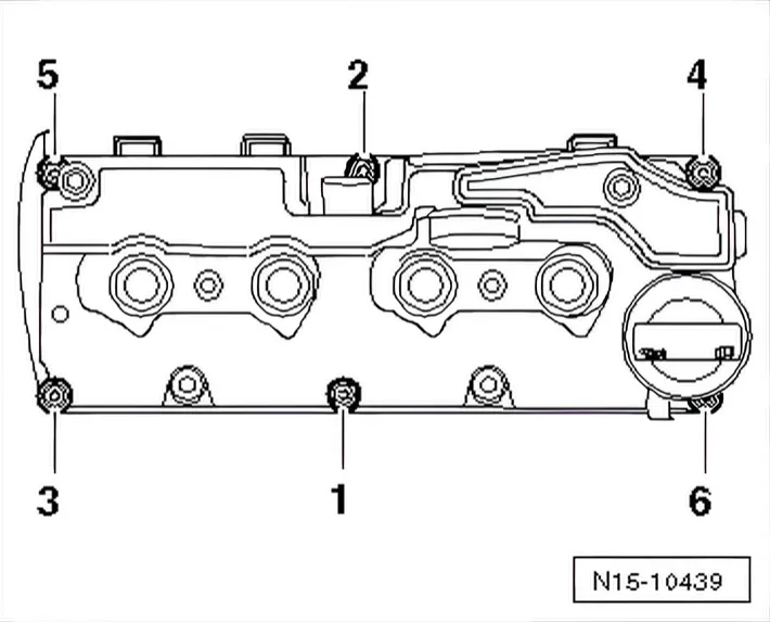
- Tighten bolts to 10 Nm in sequence 1 … 6.
- Ensure that cylinder head cover is correctly clipped to toothed belt guard.
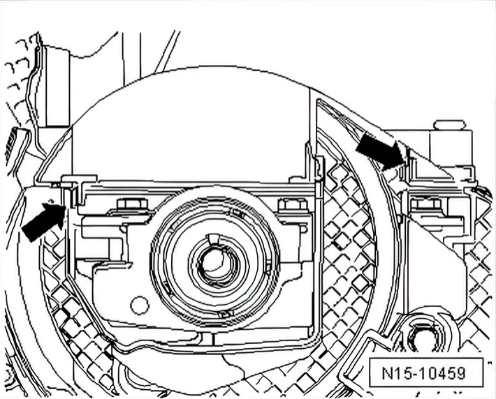
- To do this, press toothed belt guard (using a screwdriver if necessary) against cylinder head cover in area of clips -arrows- until clips audibly engage in each other.
- Check clearance between hub and toothed belt guard.
After any work on the fuel system
Connect a ⇒ Vehicle diagnostic tester.
Perform the function “Fuel pump activation (Filling/bleeding fuel system)” in “Guided functions” ⇒ 1.3 Filling/bleeding fuel system.
1.4.1 Removing and installing injector seal in cylinder head cover
⇒ 1.1.1 Schematic overview - fuel system, Polo
Special tools and workshop equipment required
- Lambda probe open ring spanner set - 3337-
- Tool set - T10055-
- Assembly tool - T10208/2-
- Torque wrench - V.A.G 1331-
- Tool set - T10133-
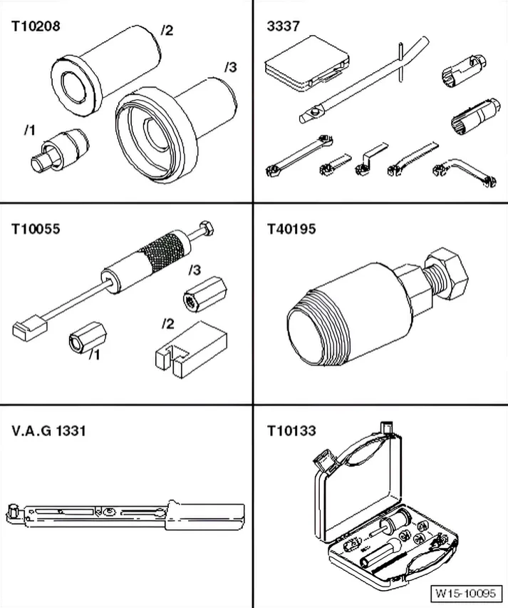
- Seal puller - T 40195-
Special tools and workshop equipment required
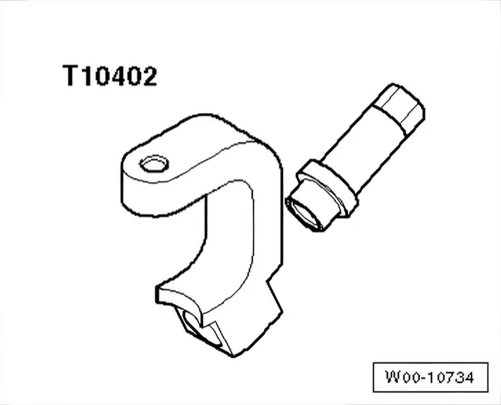
- Injector remover - T40402-
Removing
- Remove engine cover panel ⇒ 3 Engine cover panel.
- Remove noise insulation at injectors.
- Remove only injectors for which the injector seal is to be renewed ⇒ 3.5 Removing and installing injectors.
- Move affected return lines slightly aside.
Adhere strictly to rules of cleanliness. No dirt must be allowed to enter the disconnected fuel return lines or the open connections on the injectors.
Adhere strictly to rules of cleanliness. No dirt may get into the injector holes on the cylinder head cover.
First remove leaked oil or fuel with workshop equipment.
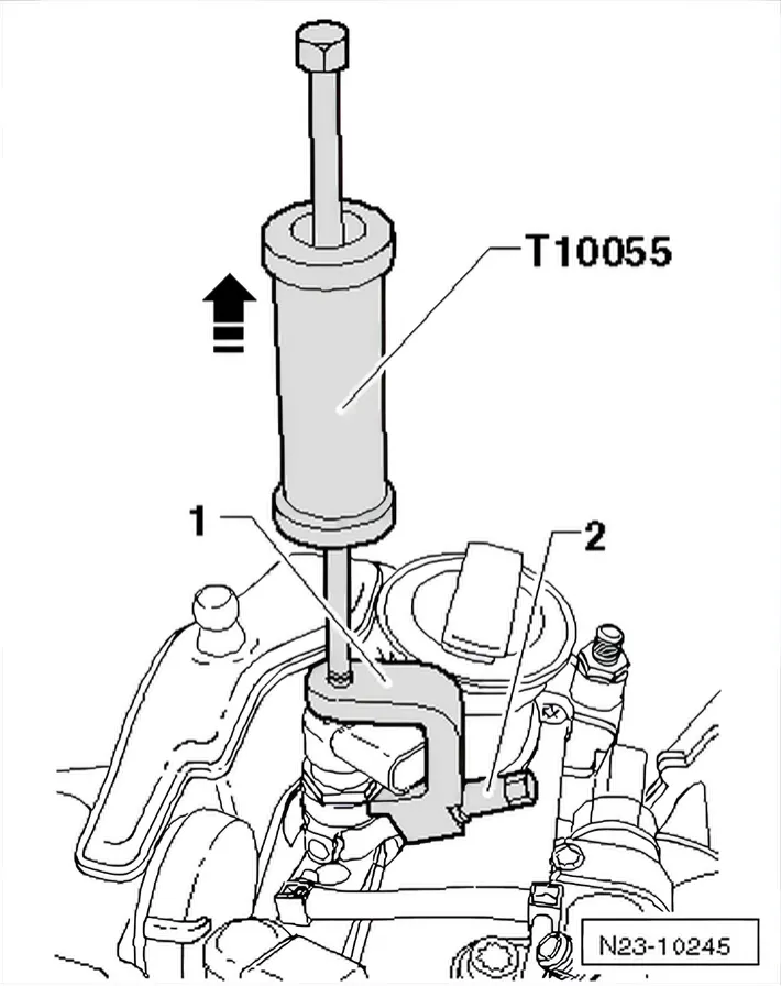
- Apply puller - T10055- with injector remover - T10402- -1- and -2- as shown in illustration and pull injectors out upwards by tapping gently.
- Using great pressure, screw oil seal extractor - T40195- as far as possible by hand into seal.
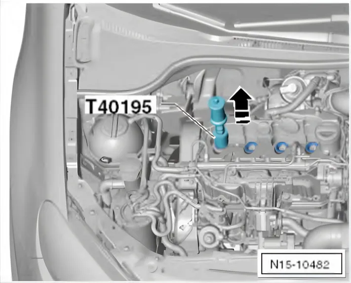
Pull the injector seal upwards by tapping gently using the seal extractor - T40195-, the adapter - T10133/2- and the slide hammer - T10133/3-.
- After removal, check whether the spring washer is still on the old seal.
If not, check that the spring washer is not still on the injector seat.
Installing
Remember that the cylinder head cover is made of plastic.
A plastic cylinder head cover is damaged easily during repairs.
Check cylinder head cover for damage.
- Fit new injector seal by hand initially.
- Then carefully push the new injector seal in as far as it will go with the assembly tool - T10208/2-.
Further assembly is carried out in the reverse order of removal.
Tightening torques on this page
1 torque
In the steps
| Step | Torque |
|---|---|
| Tighten bolts to 10 Nm in sequence 1 … 6. | 10 Nm |