
Towing bracket 6R0092155 with electrical kit 6C0055204
Fitting instructions for the towing bracket (coupling ball with bracket, Westfalia) and the 13-pin electrical kit for the VW Polo 6R/6C.
Coupling ball with bracket
- Part number:
- 6R0 092 155
- Vehicle:
- Polo 2009–2013, Polo 2013–, Polo BlueMotion 2013–, Polo Cross 2013– (6R)
Towing vehicle
Manufacturer: VOLKSWAGEN AG
Model:
- Polo 2009→2013
- Polo 2013→
- Polo BlueMotion 2013→
- Polo Cross 2013→
Official Model Designation: 6R
Refer to vehicle registration doucments /Owner's Manual for the maximum permissible trailer load or drawbar load in kg approved by the manufacturer for the above model.
Coupling ball with bracket:
| Westfalia-Model | 321 740 |
|---|---|
| EC-No. | e13*94/20-2896 |
| Drawbar ratio | 7,0 kN |
| Perm. drawbar load | 50 kg |
The tested drawbar ratio is 7,0 kN. This equals, for example, a trailer load of 1200 kg and a permissible gross weight of 1710 kg. The applicable figures though are those stated in the vehicle registration documents. The tested drawbar ratio must not be exceeded. Do not exceed the permissible drawbar load.
The towing hitch is designed for towing trailers fitted with a towing ball coupling and for operating load carrying systems, which have been approved for hitching onto the coupling ball. Any other use is forbidden. Operation must suit the road conditions..
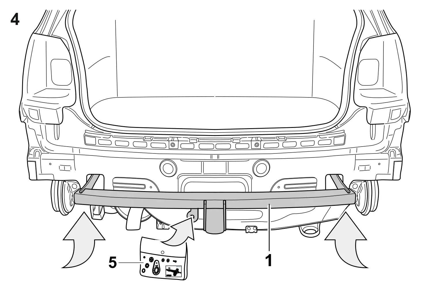
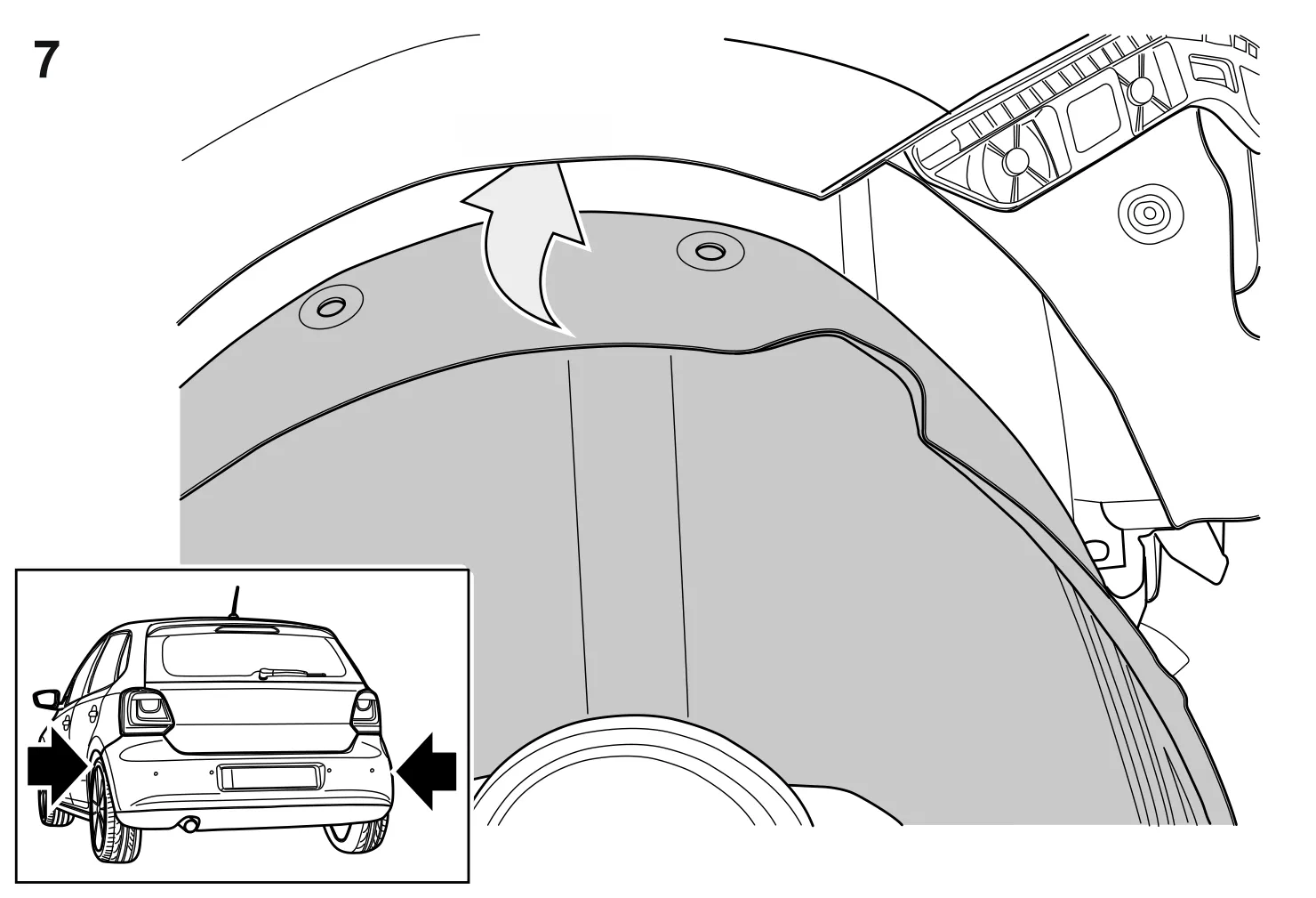
The manufacturer's standard approved fixing points are used.
In EC and non-EC countries, adopt the relevant procedure in accordance with local regulations.
These fitting and operating instructions must accompany the vehicle documents.
Electrical system should be installed in accordance with ISO 1724 (7-pin) or ISO 11446 (13-pin). The socket mount is prepared for alternatively fitting a 7-pin or 13-pin socket.
The coupling ball with bracket including all the parts for fitting weighs 18 kg. Please note that the unladen weight of your vehicle is increased by this amount after fitting the coupling ball with bracket.
The ball head should always be kept clean and slightly greased. However, if track stabilization equipment is used, the ball coupling must be greasefree. Please follow information given in the respective operating instructions.
The diameter of the ball head should be inspected from time to time. As soon as a diameter of 49 mm is reached at any time, the coupling ball and bracket must not longer be used for safety reasons.
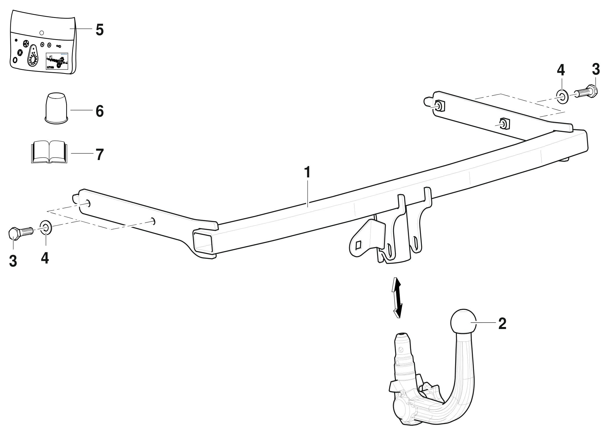
| Item | Designation | Qty |
|---|---|---|
| 1 | Towing hitch base part | 1 |
| 2 | Ball rod | 1 |
| 3 | Hexagon screw M10x35 (10.9) | 4 |
| 4 | Washer 10,5x30x3 | 4 |
| 5 | Socket holder | 1 |
| 6 | Ball protective cap | 1 |
| 7 | Fitting instructions | 1 |
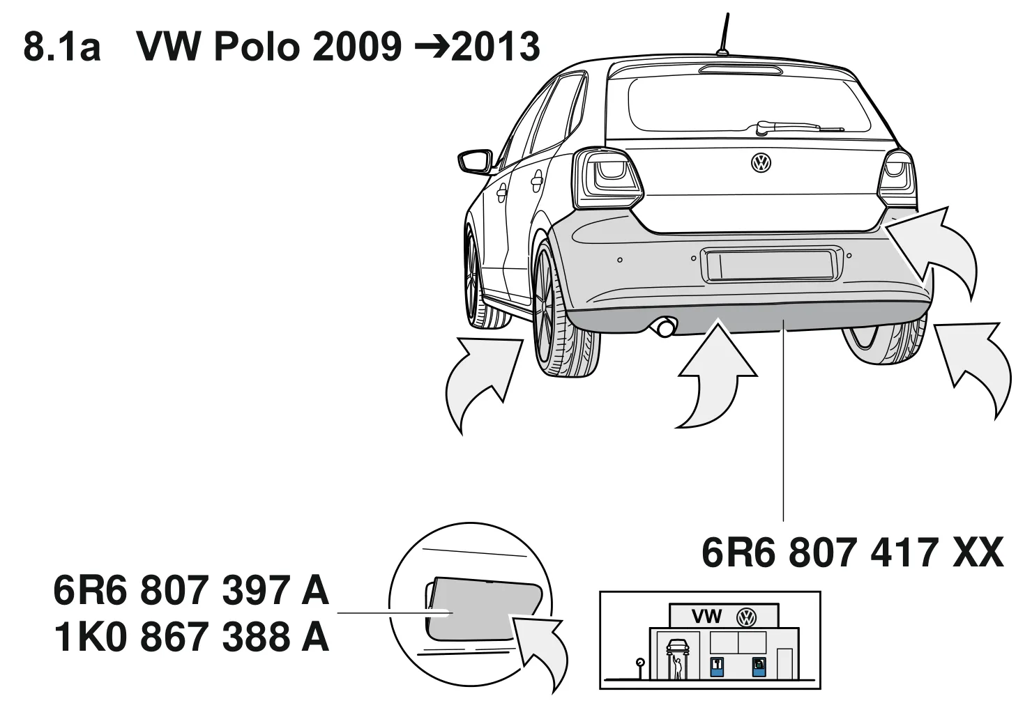
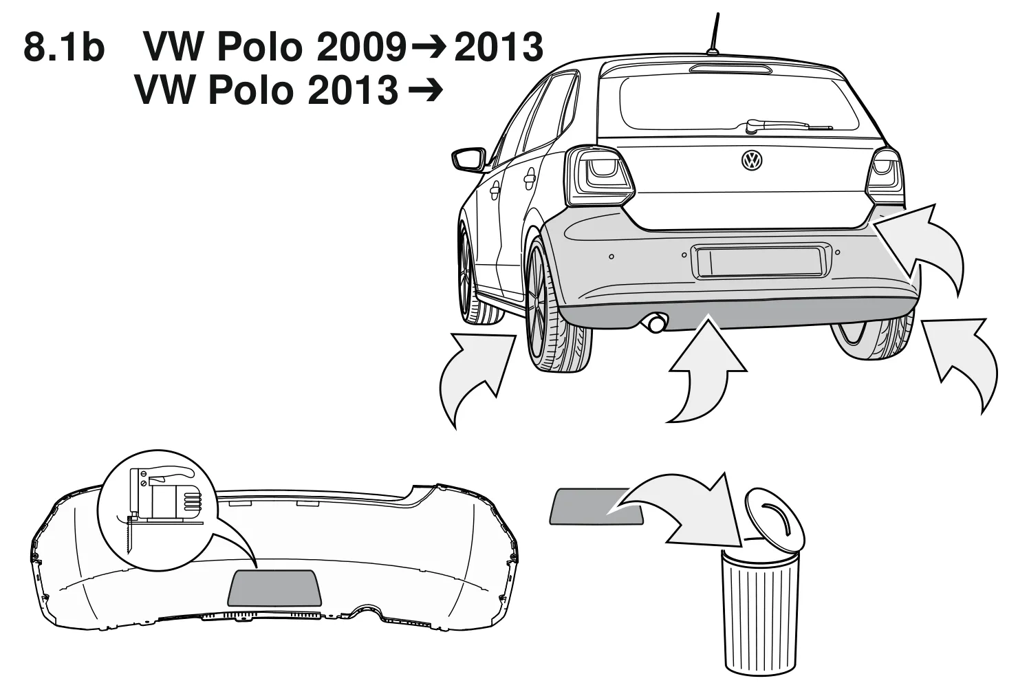
| 8* | Bumper (6R6 807 417 XX) | 1 |
| 9* | Flap (6R6 807 397 A + 1K0 867 388 A) | 1 |
We reserve the right to make changes to the scope of supply.
* Order these part over VE-Kassel
The clearance specified in appendix VII, diagram 30 of guideline 94/20/EG must be guaranteed.

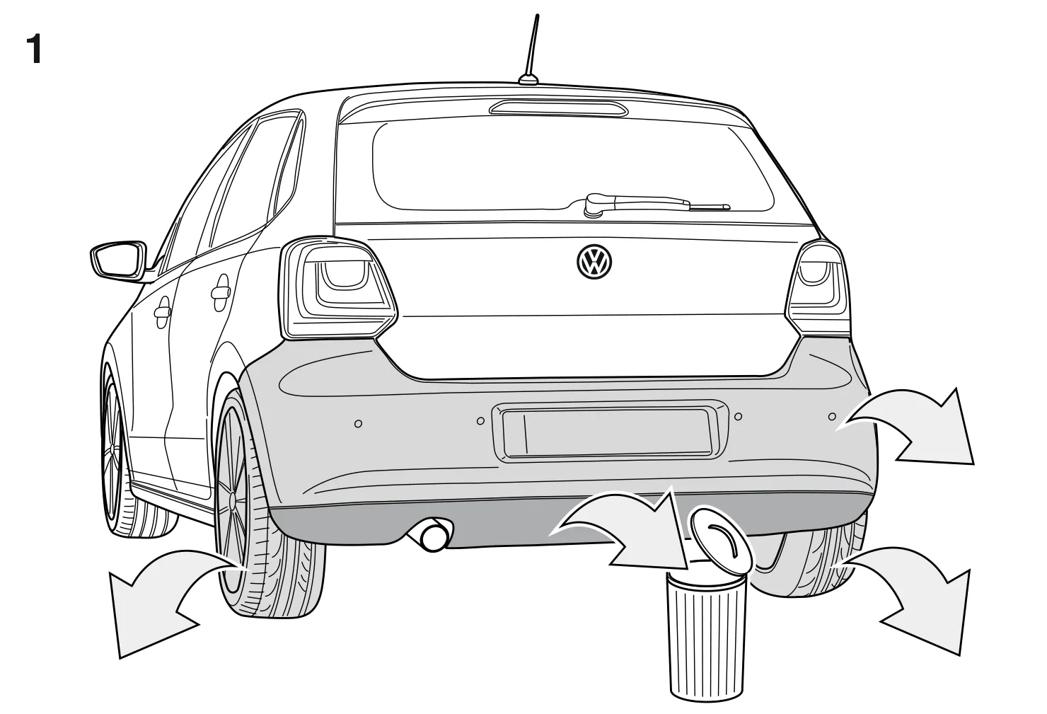
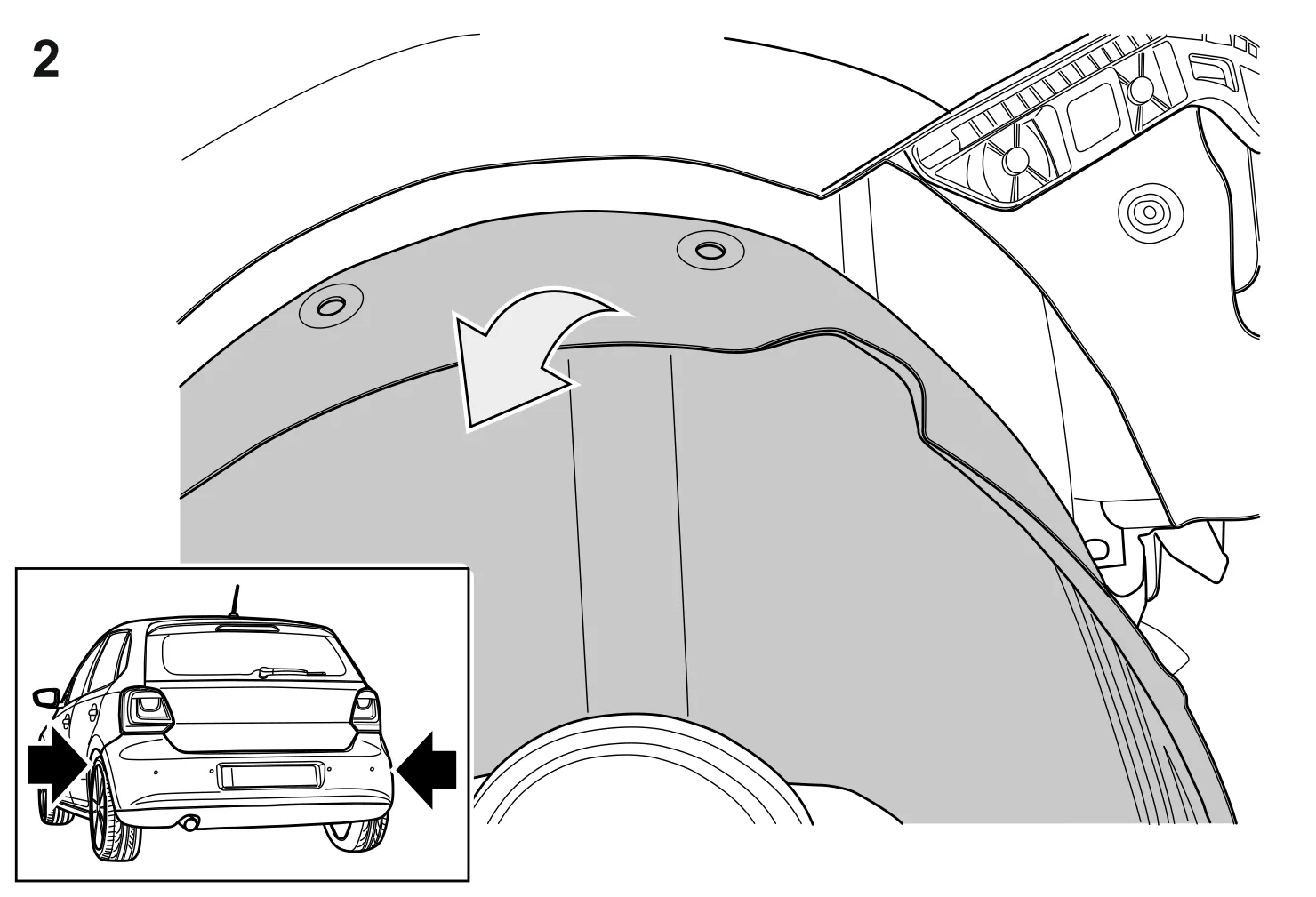
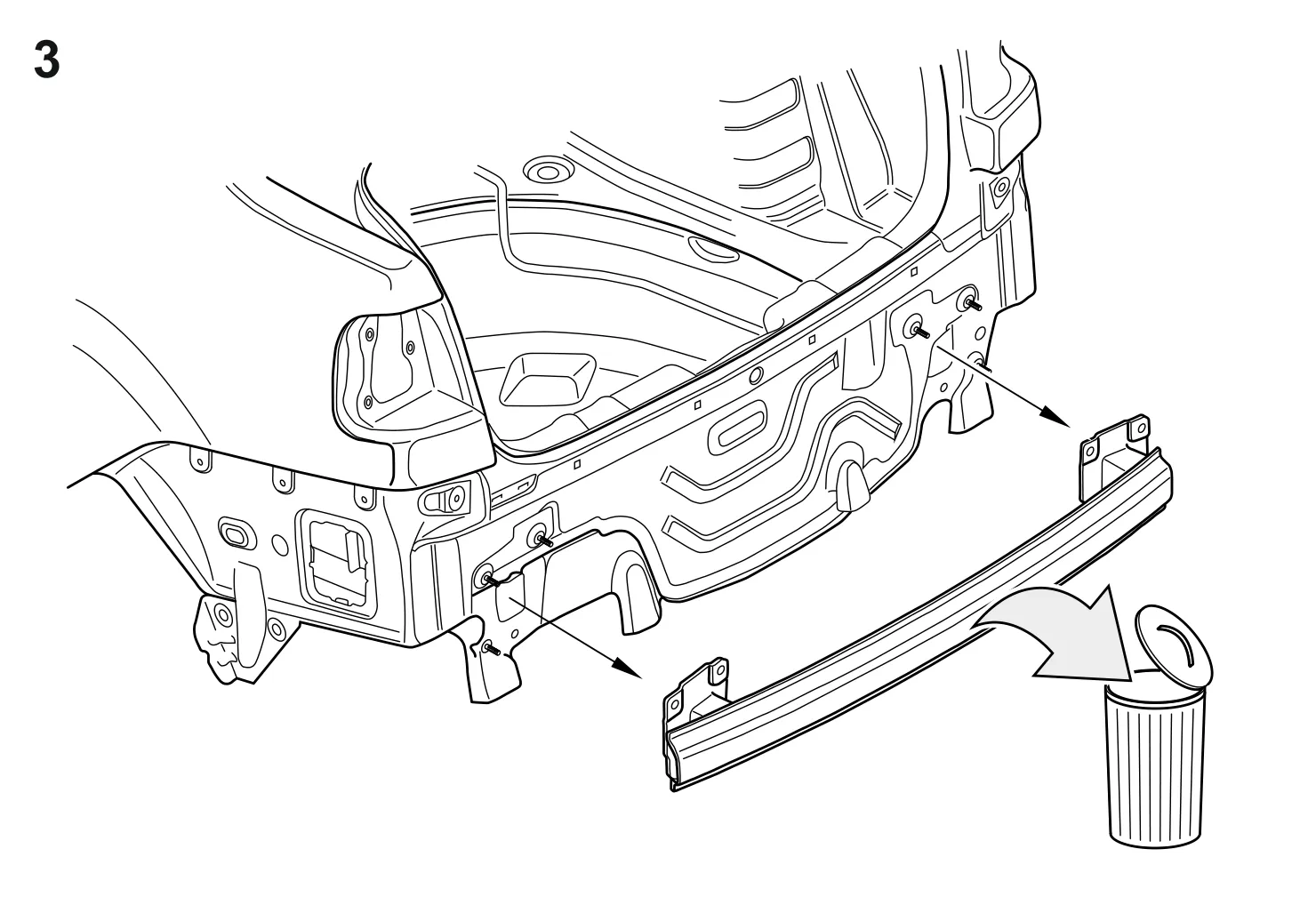


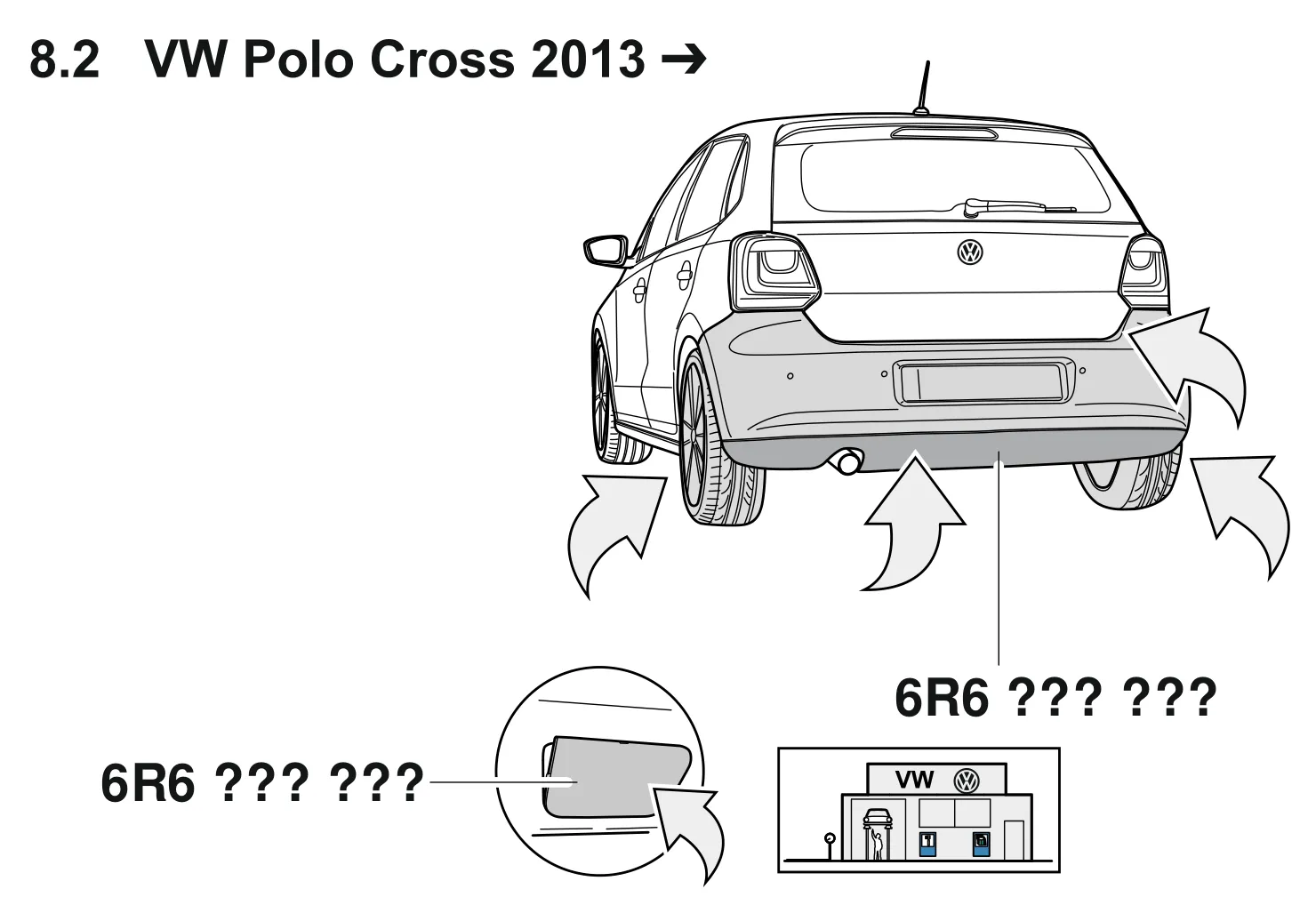
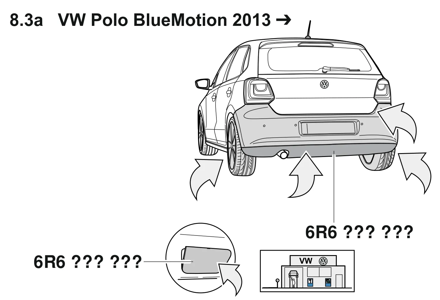
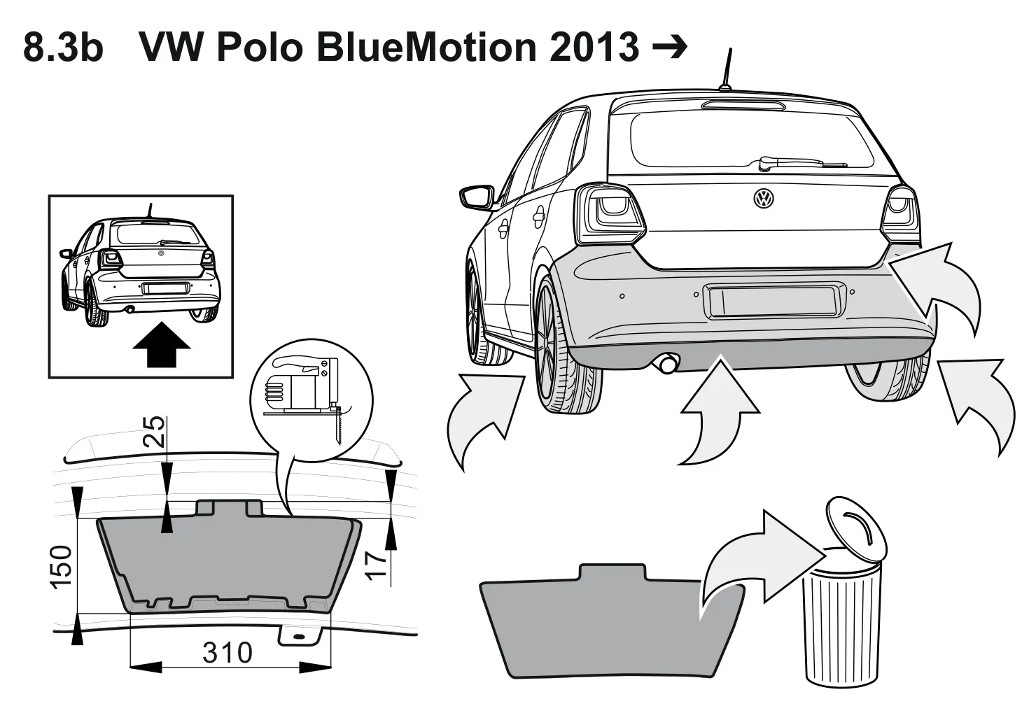
Electrical installation kit
- Part number:
- 6C0 055 204
- Vehicle:
- VW Polo A05 GP 22/2014 >>
Scope of delivery:
- 1× Wiring harness, 12-wire with pre-assembled socket insert
- 1× Wiring harness, 9-wire
- 1× Socket housing
- 3× Screws M5 x 24
- 3× Nuts M5, self-locking
- 1× Trailer connection unit
- 1× 30A flat pin fuses
- 2× 20A flat pin fuses
- 1× 3-way socket housing, black
- 1× 4-way socket housing, brown
- 1× 1-way flat plug housing, brown
- 20× Cable ties 140mm long
- 1× Cable ties 300mm long.
For vehicles without a factory-fitted reverse parking assistance system, additional parts (6C0.971.362.A bracket plus mounting and insulation materials) are required for fitting the trailer connection unit, see ETKA.
Work to be carried out, general:
- Disconnect the earth cable from the battery.
- Fit the 12- and 9-wire wiring harnesses as well as the socket housing.
- Function test.
1. Disconnect the earth cable from the battery
To avoid short-circuits during fitting and for safety reasons, the earth cable must, without exception, be disconnected from the battery before starting work (risk of fire)!!
Attention: On-board computer / immobiliser!
Disconnection of the battery can lead to a loss of stored data! Observe the manufacturer's instructions!!
Before starting work, read out the error memory!
2. Fit the 12- and 9-wire wiring harnesses as well as the socket housing.
- Take out the parcel shelf and the luggage compartment floor coverings and then remove the rear body panel trim.
- Fold the rear seat forward and then remove the left backrest.
- Loosen the right side trims at the rear of the luggage compartment and fold them inwards slightly.
- Remove the left luggage compartment and rear seat trims.
- All of the access trims on the left must be removed.
- Remove the left storage compartment in the dash panel.
- Remove the covers from the left front face of the dash panel.
- Remove the bonnet release lever and side trim in the left footwell.
- Remove the cover from the fuse box and then remove the fuse box.
- Remove the 40 mm cable bushing in the rear panel for the wiring harness to the bumper trim (bumper trim already removed to fit the coupling) and then pull the vehicle's bumper trim wiring harness inwards into the luggage compartment.
- Route the 12-wire wiring harness with the pre-assembled socket insert through the body opening in the rear panel from the inside to the outside.
- Open the second channel in the grommet in the 12-wire wiring harness at the marking (groove) and then use a suitable spreading tool to guide the bumper trim wiring harness through the now open second channel in the grommet from the inside to the outside. To simplify the process, the connector housings on the vehicle wiring harness for the number plate lights and for the parking assistant sensor connections can be removed using a suitable release tool to release the plug contacts (make a note of the plug assignment beforehand).
- Pull the bumper trim wiring harness as far as it will go so that the existing rubber grommet lies directly against the grommet in the 12-wire wiring harness.
- Insert the grommet into the opening hole in the rear panel and make sure it is correctly seated!
- Use a 300 mm cable tie to secure the 12-wire wiring harness to the outside of the towing hitch cross member, lay it on the socket mounting plate and mount the socket housing together with the preassembled socket insert on the towing hitch mounting plate as follows:
Towing hitch with closed socket mounting plate:
- Cleanly prepare the perforated, archway-shaped area on the right and flattened side of the socket housing (when looking from the front), so that the outlet is on the right. Carefully remove the socket seal for the centre outlet, which is not needed here, without damaging the insulating sleeve! Insert the pre-assembled socket insert of the wiring harness in the socket housing, click it into the supports and then use the pre-fitted screws in the socket housing to mount it on the towing hitch mounting plate. The M5 x 24 screws and M5 nuts supplied in the kit are not needed here (see Fig. 1).
Towing hitch with open socket mounting plate:
- Unscrew the pre-fitted M5 x 14 screws from the socket housing (not needed in this case). Carefully remove the socket seal for the side outlet, which is not needed here, without damaging the insulating sleeve! Insert the pre-assembled wiring harness socket insert into the socket housing supplied, click in place in the supports and mount it on the towing hitch mounting plate using the supplied M5 x 24 screws and M5 nuts(see Fig. 2).

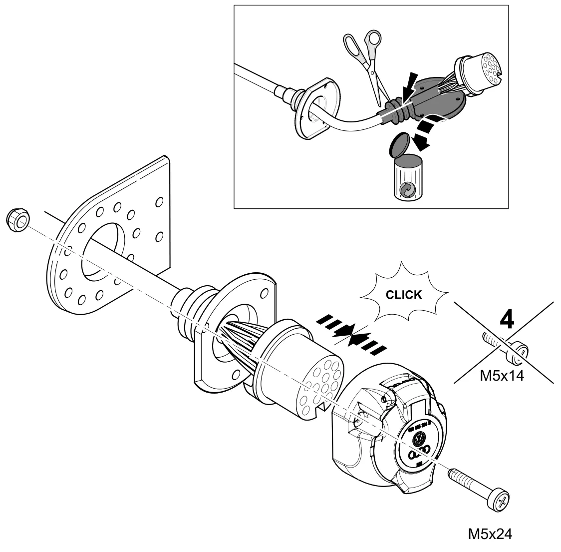
The socket allocation is as follows:
| Wire | Contact no. | Function |
|---|---|---|
| blue / yellow | 1 | Left directional indicator |
| blue / white | 2 | Rear fog light |
| brown | 3 | Earth (for contact nos. 1 to 8) |
| blue / green | 4 | Right directional indicator |
| grey / yellow | 5 | Right rear light |
| white / green | 6 | Brake lights |
| grey/red | 7 | Left tail light |
| black/green | 8 | Reversing light |
| red/white | 9 | Power supply permanent positive trailer (Ter. 30) |
| blue/red | 10 | Power supply charging cable trailer (Ter. 15) |
| brown | 11 | Earth (for contact no. 10) |
| not occupied | 12 | Trailer detection control wire |
| brown | 13 | Earth (for contact no. 9) |
- Insert and click into place the three 6-way, 10-way and 24-way connector housings for the 9- and 12-wire wiring harnesses in their intended sockets in the trailer connection unit.
- Use the necessary material (bracket, securing and insulation materials) to secure the trailer connection unit in its intended position on the right of the luggage compartment. The trailer connection unit bracket is already fitted in the case of vehicles with a factory-fitted reverse parking assistant system, as it is combined with the parking assistant control unit's bracket.
- Connect the cable eyes from the four brown wires in the 12-wire and 9-wire wiring harnesses to the vehicle earthing point on the left side of the luggage compartment.
- Connect the two-wire wire ends of the 9-wire wiring harness to the brown/black wires on the left side as follows:
- Undo and separate from the bracket the vehicle's 5-way, black flat plug housing that connects up the tailgate wiring harness.
- Use a suitable release tool to release the black/brown cable with the 1.5 mm spade contact from chamber 2 in the black flat plug housing and plug it into the 1-way, brown flat plug housing (brake light signal for the third braking light).
- Insert the brown/black wire end with the 1.5 mm spade contact on the 9-wire wiring harness into the now free chamber 2 in the vehicle's 5-way, black flat plug housing and then click it into place.
- Plug the vehicle's 5-way, black flat plug housing back in and secure it on the bracket.
- Plug the two remaining 1-way, brown flat plug housings back in and use a 140 mm cable tie to secure them to a suitable place.
- The 12- and 9-wire wiring harnesses must be secured, using the 140 mm cable ties supplied, to the vehicle's wiring harness on the rear panel.
- Route the remaining wire ends from the 9-wire wiring harness along the wiring harness on the left side of the vehicle until it reaches the front of the driver's footwell and then use the 140 mm cable ties to secure them in place.
- Route the red/white, red/blue and black/red cable ends in the 9-wire wiring harness up to the fuse box and insert and click them into the unoccupied, output side fuse slots (marked with an "A", e.g. "F44A") as shown in Table 2.
| Wire | Fuse slot no. | Fuse rating | Function |
|---|---|---|---|
| red/white | F 44A | 20A | Power supply trailer lighting right |
| blue/red | F 8A | 20A | Power supply trailer lighting left |
| black/red | F 13A | 30A | Power supply permanent positive and charging cable trailer (Ter. 30 + Ter. 15) |
- Fit the three flat pin fuses supplied into their respective fuse slots as shown in Table 2 and click them into place.
- Route the orange/brown, orange/green and black/red wire ends in the 9-wire wiring harness up to the BCM (Body Control Module).
- Unlock the socket "C" connector housing on the BCM and then pull the connector strips out of the housing casing. Remove the cable ties previously fitted at the connector housing's cable output.
- Push the socket contact on the vehicle's black/red wire out of chamber 57 and insert it into chamber 2 in the supplied 3-way, black socket housing and then click it into place.
- Insert the socket contact at the black/red wire endof the 9-wire wiring harness into the now free chamber 57 and click it into place.
- Push the socket contact on the vehicle's orange/green wire out of chamber 46 and insert it into chamber 3 in the supplied 4-way, brown socket housing and then click it into place.
- Push the socket contact of the vehicle's orange/brown wire out of chamber 47 and insert it into chamber 4 in the 4-way, brown socket housing and then click it in place.
- Insert the socket contacts at the orange/green and orange/brown wire ends of the 9-wire wiring harness into the now free chamber 46 (orange/green) and chamber 47 (orange/brown) and then click them into place. Reinsert the connector strips into the housing casing, lock and then use a 140 mm cable tie to secure them in place.
- Plug the 3-way, black and 4-way, brown pin housing of the wiring harness into the previously fitted 3-way, black and 4-way, brown socket housings, click into place and then use a 140 mm cable tie to secure them to a suitable place.
- Route all of the installation kit's wiring harnesses along the vehicle's wiring harnesses, secure them with the supplied cable ties and/or insert them into the existing cable holders.
- Refit all trim parts and any parts removed.
- Reconnect the earth wire to the battery.
3. Function test
Check all functions using a suitable test device.