
Original parking distance control 6R0054630B
Installation instructions for the original rear parking distance control of the Volkswagen Polo from 2009: painting the sensors, fitting them in the bumper, wiring and setup.
Installation
- Part number:
- 6R0 054 630 B
- Vehicle:
- Polo 2009– (6R)
Set contents:
- 1 x controller
- 1 x power harness
- 1 x buzzer
- 1 x sensor harness
- 4 x sensor
- 1 x installation instructions
- 4 x covering rings
- 1 x operation manual
- 1 x fixing material
Special tools, test and measuring equipment, and ancillaries required:
- Torx Allen keys (set)
- Triangular file
- Flat-bladed screwdriver
- Round file
- Side cutters
- Measuring and cutting tool
- Hand drill
- Centre punch
- Set of twist drills
- Tweezers
- Forstner bit ∅ 20 mm
- VAS 1978 wiring harness repair set
- Expanding/crimp grip pliers
Procedure:
1.1 Paint sensors
⇒ Self-study programme No. 214/215
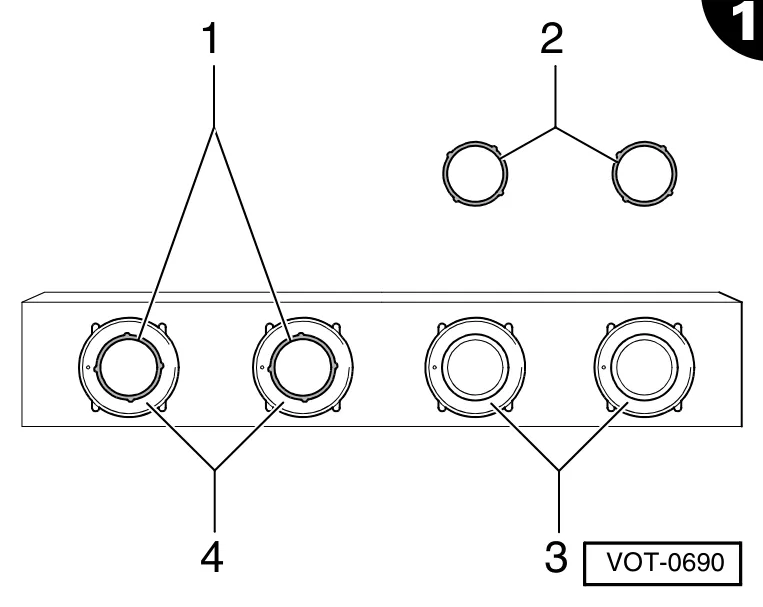
The figure gives an example of the protective rings -1- already placed in the correct position on the sensors -4-.
- Place the covering rings -2- on the rubber membranes of the sensors -3-.
- Paint the sensors -3- and -4- evenly and not too thickly, in the same colour as the car.
- Remove the covering rings -1- and -2- carefully directly after painting (while the paint is still wet) using tweezers and let the paint dry.
- Repaint as necessary after drying (e.g. clear lacquer for twin coat painting).
1.2 Fitting the components
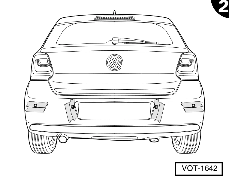
- Apply masking tape liberally in the areas where the holes are to be drilled in order to protect the bumper covering.
- Remove the bumper covering.
⇒ Exterior bodywork tasks; Repair Group 63; bumper; rear bumper; removing and refitting the bumper covering
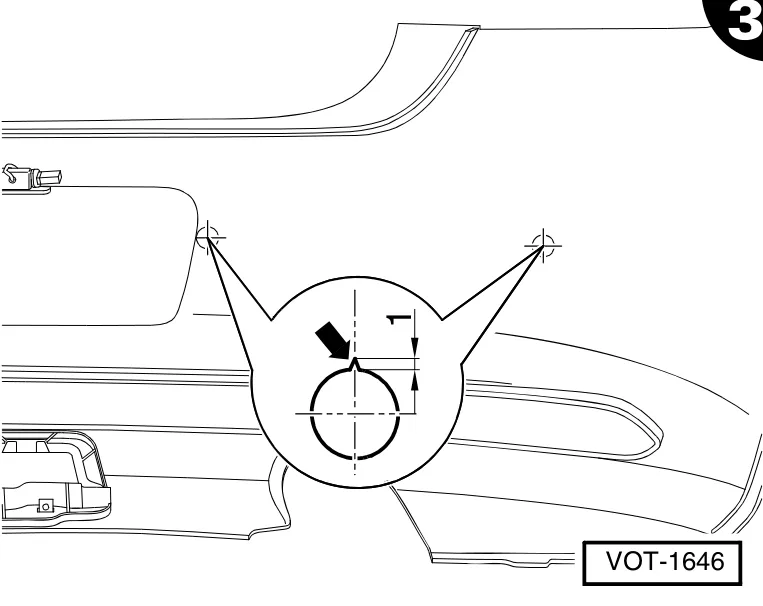
Inside the bumper covering are four circle markings to permit mounting of the sensors. The drilling positions are the centre points of these circles.
- Draw the drilling spots on the inside of the bumper covering and center punch the drilling points.
- Pre-drill the holes using a ∅ 2 mm drill bit.
- Use a ∅ 20 mm Forstner bit to drill the holes from the outside.
To counter rotating of the sensors, an upward-pointing notch -arrow- about 1 mm deep is needed in the boreholes.
- File an upward-pointing notch -arrow- with a small triangular file in all four boreholes.
- Remove the swarf from the holes for the sensors in the bumper covering.
- Take the parcel shelf and the boot mat out of the vehicle.
⇒ Interior bodywork fitting; Repair Group 70; door trims/padding; loading area and boot trims
- Remove the tailgate trim and the right hand side boot trim from the vehicle (Polo 2014 ➤ left-hand side luggage compartment trim).
⇒ Interior bodywork fitting; Repair Group 70; door trims/padding; loading area and boot trims
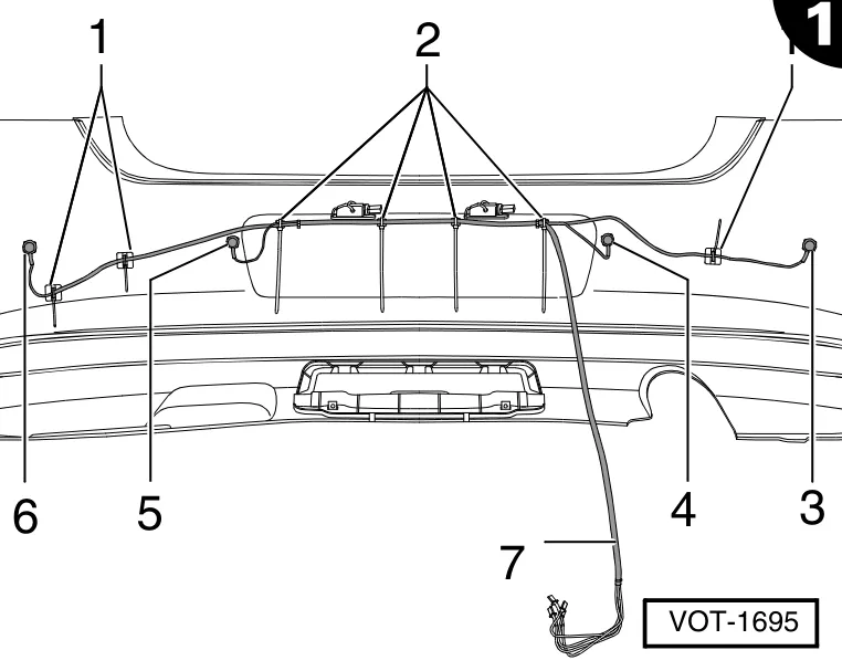
The supplied sensor harness -7- consists of four individual sensor wires. These sensor wires are numbered from 1 to 4. When routing, the sensor wire marked with 1 should be placed in the left hole drilled -3- (facing in the direction of travel). The remaining sensor wires 2...4 must be fitted consecutively, therefore wire 2 in drill hole -4-, etc.
- Route the individual sensor wires along the inside of the bumper covering to the drilled holes -3- to -6-.
- Secure the sensor wires -7- using two socket cable ties -2- supplied to the lugs of the bumper covering.
- Bond the retaining plates -1- supplied in position and secure the wiring to the retaining plates -7- using cable ties.
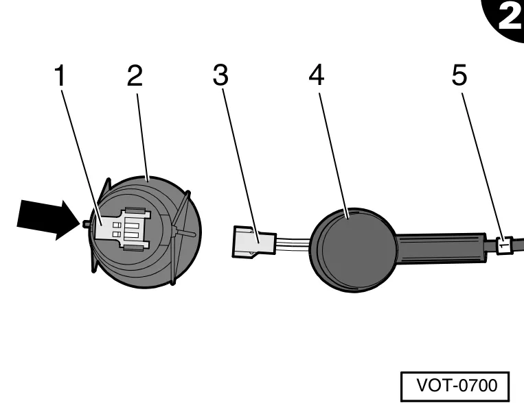
- Clip the sensors into the holes in the bumper covering.
- Push the plug -3- on to the sensor sockets -2-.
- Push the covers -4- over the sensors -2-.

- Stretch the opening of the wiring grommet -arrow- in the rear body panel using an expanding pliers.
- Thread the beginning of the sensor wiring harness through the expanded wiring grommet -arrow- into the interior of the vehicle.
- Mount the bumper covering and, when doing so, carefully continue to pull the sensor wiring harness up to the markings in the interior of the vehicle.
- Screw the bumper covering together.
⇒ Exterior bodywork tasks; Repair Group 63; bumper; rear bumper; removing and refitting the bumper covering
- Secure the sensor wiring harness with the supplied cable ties to the existing car wiring.
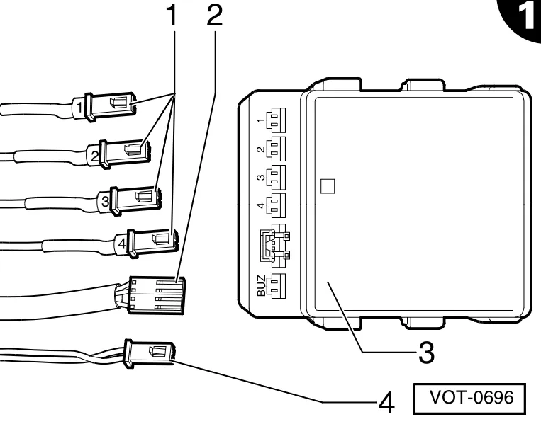
- Plug the sensor plugs -1- according to their numbering into the corresponding sockets “1” to “4” on the controller -3-, until they “click” into the fixed position.
- Push the power harness connector -2- into the associated socket on the control unit -3-, until it perceptibly engages.
- Plug the buzzer connector -4- into the associated “BUZ“ socket on the controller -3-, until it “clicks” into the fixed position.
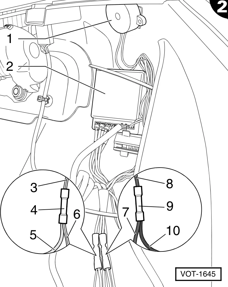
- Degrease the right fitting site in the luggage compartment for the buzzer unit -1- and the control unit-2- using a suitable cleaning agent, e.g. industrial alcohol.
- Fit the buzzer -1- and the control unit -2- with the double-sided adhesive tape as shown.
Only applies to the Polo 2009 ➤ 2013:
- Unwind approximately 50 mm harness protective tape on the vehicle wiring in the side part at the rear right.
- Cut the vehicle's black/blue wire to the tailgate light and insulate the wire ends.
- Crimp one end of the black/blue wire -3- in a duraseal connector -4-.
- Crimp the free end of the black/blue wire -6- together with the red wire -5- of the power harness in the crimp connector -4-.
- Cut the vehicle's brown wire to the tailgate light and insulate the wire ends.
- Crimp one end of the brown wire -8- in a crimp connector -9-.
- Crimp the free end of the brown wire -7- from the power harness together with the black wire -10- in the duraseal connector -9-.
- Heat-shrink the duraseal connectors -4- and -9- to seal them, using the hot air blower from the VAS 1978 harness repair set.
- Replace the harness protective tape.
- Set up the parking distance control system.
Only applies to the Polo 2014 ➤:
- Connect the black wire from the power wiring harness to the vehicle earthing point beside the rear light.
- Unwind 50 mm of the harness protective tape on the vehicle wiring up to the left-hand rear light.
- Identify the wire for the vehicle's left reversing light.
⇒ Vehicle circuit diagram or using a voltage tester on the connector for the tail light
- Cut the identified wire and strip the insulation from both ends.
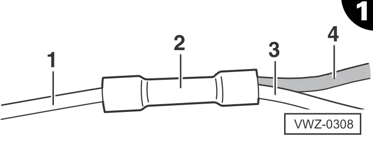
- Crimp one end -1- of the cut wire in a crimp connector -2-.
- Crimp the free end -3- of the cut wire together with the red wire -4- of the power wiring harness in the crimp connector -2-.
- Heat-shrink the crimp connector -2- to seal it, using the hot air blower from the VAS 1978 wiring repair set.
- Replace the harness protective tape.
- Set up the parking distance control system.
1.3 Setting up the parking distance control
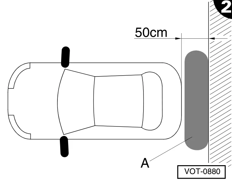
- To set up the parking distance control system reverse the vehicle until it is 50 cm from a wall.
- Switch off the engine.
- Switch on the ignition and engage reverse gear.
The controller signals the start of the learning process with a double beep. If there is no beep after engaging reverse gear, look for a fault. ⇒ 1.4 Setting up fault diagnosis
A single long tone must sound within 100 seconds - this tone denotes that the learning process has been completed successfully. If the learning process is not confirmed as complete within 100 seconds, you must look for a fault. ⇒ 1.4 Setting up fault diagnosis
- After the system has issued an audible signal to indicate successful completion of the learning process and the ignition has been switched off, disconnect the blue lead from the power leads.
- Isolate the ends of the disconnected wire.
This ends the setting up process.
- Check the parking distance control system functions using the enclosed operating instructions.
Complete final installation if all of the parking distance control system functions are working correctly. ⇒ 1.5 Final fitting, all vehicles
Establish the parking distance control fault functions - carry out a fault diagnosis and then set up again. ⇒ 1.4 Setting up fault diagnosis
1.4 Setting up fault diagnosis
- ⇒ 1.3 Setting up the parking distance control system If there is no tone after switching on the ignition and engaging reverse gear, check the power supply and the connections to the controller.
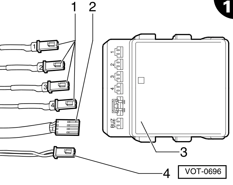
- Is there a 12 V power supply to the connector -2- when reverse gear is engaged? ⇒ Fault diagnosis as per the wiring diagram
- Is the buzzer connector -4- connected correctly? Is the blue single-core wire of the power harness disconnected? If necessary, remake the connection. If a single long tone does not sound after the double beep (start of the learning process) within a max. of 100 seconds, check the sensor connections. If a single long tone does not sound after the double beep (start of the learning process) within a max. of 100 seconds, but an intermittent beep is heard instead, then the obstacle behind the vehicle has not been detected. ⇒ Check the distance from the wall, correct as necessary, or align with another obstruction at a distance of 50 cm.
1.5 Final fitting, all vehicles
- Secure all the parking distance controller wires to existing leads or mounting plates of the vehicle using cable ties supplied.
- Replace all trims in reverse order.
⇒ Interior bodywork fitting; Repair Group 70; door trims/padding; loading area and boot trims