
Volkswagen original sound system 000051419C
Fitting and operating instructions for the Volkswagen original sound system (subwoofer with amplifier) in the luggage compartment or the spare wheel well.
Fitting and operation
- Part number:
- 000 051 419 C
Included:
- 1 x shorting plug 1)
- 1 x sub-woofer
- 1 x spacer shell 2)
- 1 x amplifier
- 1 x wiring set
- 1 x fitting material
- 1 x jumper for right-hand drive
- 1 x assembly instructions
1) Only supplied with the luggage compartment sound system. If required, order separately for the spare wheel well (for part number, see accessories).
2) Only supplied with the sound system with subwoofer in spare wheel well.
Accessories:
- DKS 051 419 A programmable dongle
- DKS 051 419 B shorting plug
- 1K0 803 899 D screw for fixing spare wheel 3) (all vehicles except Polo)
- 6Q0 803 899 B screw for fixing spare wheel 3) (only for Polo)
- tyre sealant 4)
- air compressor 4)
3) is required if the existing screw is too short or is missing in the vehicle. Not included in the kit, please order separately if required.
4) is recommended if the assembly is carried out on a vehicle with a spare wheel (In this case the spare wheel is no longer required and is replaced by a breakdown kit). Please observe the local legal regulations regarding the spare wheel in the vehicle. Not included in the kit, please order separately if required.
Required special tools, test and measuring equipment and auxiliary equipment:
- VAS 1978 wiring harness repair set
Installation process:
1.1 Preparation work on the vehicle
- If it is present, remove the information electronics control unit. Otherwise remove the radio / navigation system.
- Remove the parcel shelf from the vehicle.
- Remove the luggage compartment floor from the vehicle.
- Remove the rear bench seat.
- Remove the sill rail on the right side (left-hand drive) or left side (right-hand drive).
- Remove the A-pillar trim at the bottom right side (left-hand drive) or bottom left side (right-hand drive).
- Remove the glove compartment.
1.2 Installation overview
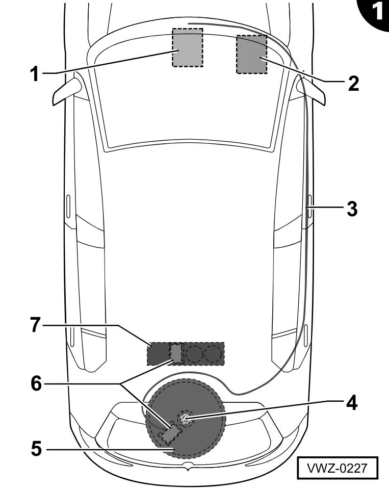
1 - Radio / navigation system
- Fitting depends on the vehicle's equipment
- not supplied
2 - Information electronics control unit
- Fitting depends on the vehicle's equipment
- not supplied
3 - Wiring harness
- Part number CHW 051 419 B
4 - Screw for fixing spare wheel
- Use the one present in the vehicle or order separately.
5 - Subwoofer
- Part number SUB 051 419 A
- Installation in spare wheel well
6 - Amplifier
- Part number AMP 051 419 C
- Installation in subwoofer -5- or -7-
7 - Subwoofer
- Part number SUB 051 419 B
- Installation in the luggage compartment
1.3 Positioning the wiring
- Fix the wiring harness supplied, to release the strain, on a diagonal strut behind the glove compartment. When doing this, please take into account the length of the wiring harness to the information electronics control unit in the glove compartment or to the radio / navigation system in the dashboard / central console.
- Route the wiring harness into the luggage compartment of the vehicle.
- Secure the wiring harness to the existing cables and holders in the car using cable ties.
1.4 Connect the wiring harness
for vehicles with DIN/ISO radio connection only:
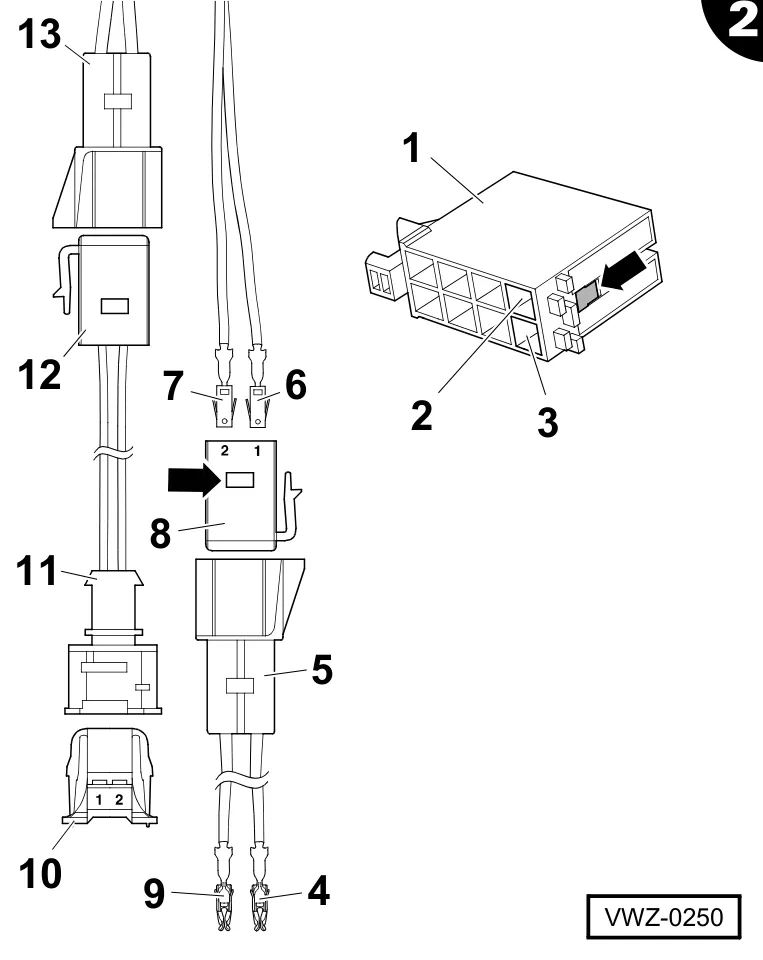
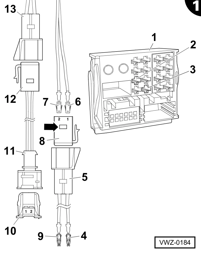
- Insert the socket connector -12- of the adapter supplied in the bush -13- of the wiring harness and lock in place.
- Remove the safety pin -arrow- on the 2-pole contact housing -8- supplied.
- Engage the contact -6- of the yellow cable of the wiring harness into chamber 1 of the contact housing -8-.
- Engage the contact -7- of the wiring harness’ yellow cable into chamber 2 of the contact housing -8-.
- Push the safety pin -arrow- into the contact housing -8-.
- Insert the contact housing -8- into the bush -5- of the adapter supplied and lock.
- Pull out the safety pin -arrow- from the black radio plug connector -1-
- Press out the contact from chamber 7 -2- of the black radio plug connector and engage it into chamber 1 of the supplied contact housing -10-.
- Press out the contact from chamber 8 -3- of the black radio plug connector and engage it into chamber 2 of the contact housing -10-.
- Close the safety catch on the contact housing -10-.
- Insert the contact housing -10- into the bush -11- of the adapter and engage it.
- Engage the contact -4- of the yellow single wire on the wiring harness into chamber 7 -2- of the black radio plug connector.
- Engage the contact -9- of the black single wire on the wiring harness into chamber 8 -3- of the black radio plug connector.
- Push the safety pin -arrow- into the radio plug connector -1-.
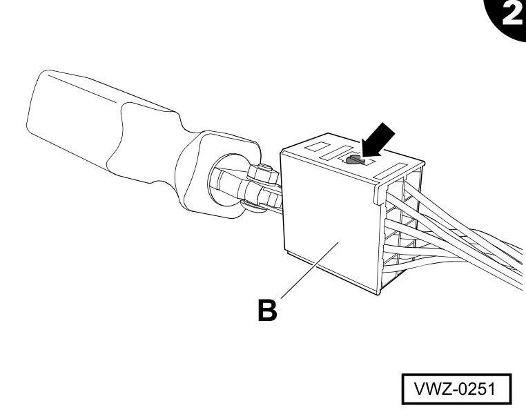
- Pull the safety pin -arrow- out of the brown plug -B- on the wiring harness and press out all the wires.
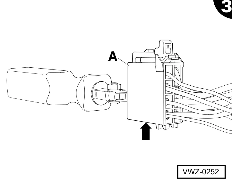
- Pull the safety pin -arrow- out of the brown plug -A- on the vehicle wiring harness.
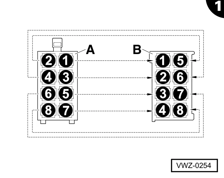
- Press the single wires individually out of the brown plug -A- and engage it in the brown plug -B-. Tick off the steps you have carried out in the “completed” column.
| Speakers | Plug -A- chamber no. | Plug -B- chamber no. | Completed |
|---|---|---|---|
| Rear right (+) | 1 | 1 | |
| Rear right (-) | 2 | 5 | |
| Front right (+) | 3 | 2 | |
| Front right (-) | 4 | 6 | |
| Front left (+) | 5 | 3 | |
| Front left (-) | 6 | 7 | |
| Rear left (+) | 7 | 4 | |
| Rear left (-) | 8 | 8 |
- Push the safety pin into plug -B- (see page 3, figure 3)
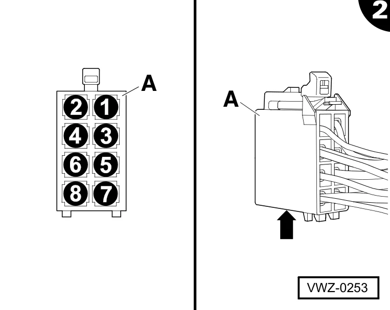
- Engage the single wires of the vehicle wiring harness in the brown plug -A- in accordance with the table below and tick off the steps you have carried out in the “completed” column.
| Speakers | Wire colour | Chamber no. | Completed |
|---|---|---|---|
| Rear right (+) | Violet | 1 | |
| Rear right (-) | Violet/black | 2 | |
| Front right (+) | Grey | 3 | |
| Front right (-) | Grey/black | 4 | |
| Front left (+) | White | 5 | |
| Front left (-) | White/black | 6 | |
| Rear left (+) | Green | 7 | |
| Rear left (-) | Green/black | 8 |
- Push the safety pin -arrow- into plug -A-.
- Complete the device connections (e.g. aerial cable) and fit the devices.
only vehicles with an old radio terminal block:
- Insert the socket connector -12- of the adapter supplied in the bush -13- of the wiring harness and lock in place.
- Remove the safety pin -arrow- on the 2-pole contact housing -8- supplied.
- Engage the contact -6- of the yellow cable of the wiring harness in the chamber 1 of the contact housing -8-.
- Engage the contact -7- of the black cable of the wiring harness in the chamber 2 of the contact housing -8-.
- Push the safety pin -arrow- into the contact housing -8-.
- Insert the contact housing -8- into the bush -5- of the adapter supplied and lock.
- Pull out the locking pin from the radio terminal block -1-.
- Push the contact out of the chamber D15 -2- of the radio connection block and lock it in chamber 1 of the contact housing -10- supplied.
- Push the contact out of the chamber D12 -3- of the radio terminal block and lock it in chamber 2 of the contact housing -10-.
- Close the fuse for the contact housing -10-.
- Insert the contact housing -10- into the bush -11- of the adapter and lock.
- Engage the contact -4- of the yellow wire on the wiring harness into chamber D15 -2- of the radio terminal block.
- Engage the contact -9- of the black wire on the wiring harness into chamber D12 -3- of the radio terminal block.
- Press the locking pin into the radio terminal block.
only vehicles with a new radio terminal block:
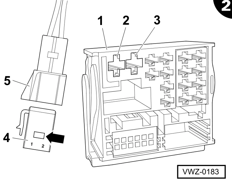
- Pull out the locking pin from the radio terminal block -1-.
- Remove the safety pin -arrow- on the 2-pole contact housing -4- supplied.
- Push the contact out of the chamber D18 -2- of the radio terminal block and lock it in chamber 1 of the contact housing -4-.
- Push the contact out of the chamber D17 -3- of the radio terminal block and lock it in chamber 2 of the contact housing -4-.
- Push the safety pin -arrow- into the contact housing -4-.
- Insert the contact housing -4- into the bush -5- of the wiring harness and lock.
- Engage the contact of the yellow wire on the wiring harness into chamber D18 -2- of the radio terminal block.
- Engage the contact of the black wire on the wiring harness into chamber D17 -3- of the radio terminal block.
- Press the locking pin into the radio terminal block.
all vehicles with old or new radio terminal block:
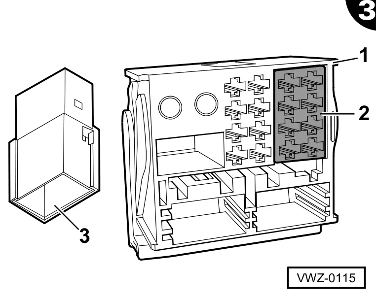
- Unlock the plugs -2-, press them out of the radio terminal block -1- and push and engage them into the socket -3- of the wiring harness.
- Push and engage the wiring harness plugs into the radio terminal block -1-.
- Complete the device connections (e.g. aerial cable) and fit the devices.
1.5 Fitting and connecting the amplifier on the sub-woofer
subwoofer in spare wheel well:
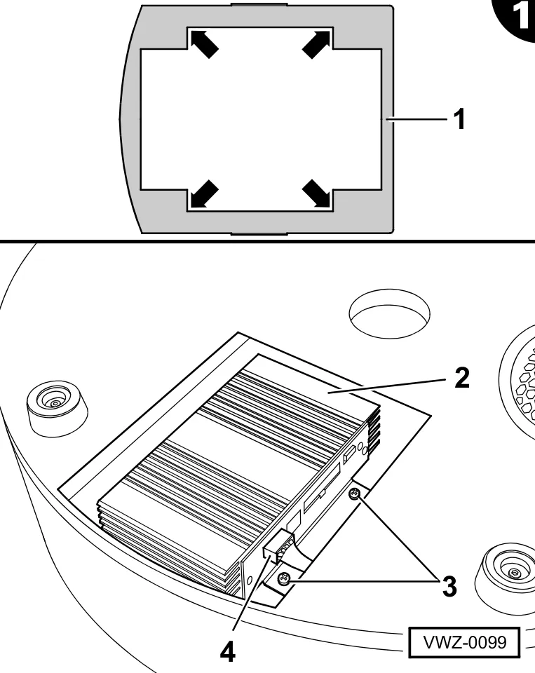
- Insert the supplied amplifier -2- into the template -1- on the rear of the sub-woofer.
- Align the amplifier angle bracket in the corners of the template and screw to the sub-woofer with each of two screws at the front -3- and rear (not shown).
- Remove the template -1-.
- Insert and engage the sub-woofer connection wire plug -4- to the amplifier.
subwoofer in luggage compartment:
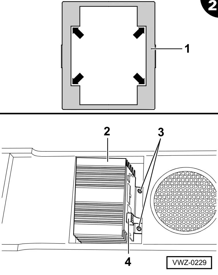
- Insert the supplied amplifier -2- into the template -1- on the rear of the subwoofer.
- Align the amplifier angle bracket in the corners of the template and screw to the subwoofer with two screws each at the front -3- and rear (not shown).
- Remove the template -1-.
- Insert and engage the subwoofer connection wire plug -4- to the amplifier.
1.6 Code the amplifier
- Code the amplifier for the vehicle, using the programmable dongle (special tool required, not in the scope of delivery; refer to Page 33).
⇒ Operating instructions programmable dongle
all right-hand drive vehicles:
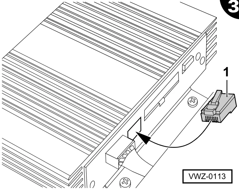
The amplifier must be re-coded for use in right-hand drive vehicles. This takes place through the insertion of a jumper into the socket on the amplifier. The jumper may not be inserted on left-hand drive vehicles.
- Insert and engage the supplied jumper -1- into the socket on the amplifier.
1.7 Fitting the sub-woofer
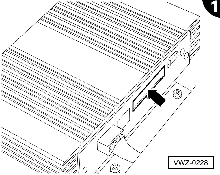
- Insert and engage the plug connector of the wiring harness into the socket -arrow- on the amplifier.
subwoofer in spare wheel well:
- Remove the spare wheel or tool box from the spare wheel well
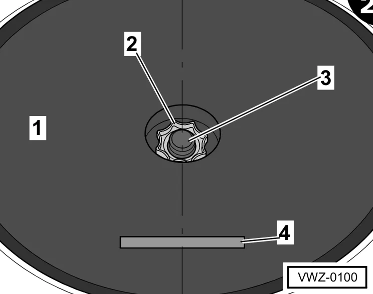
- Insert the sub-woofer -1- into the spare wheel well until it rests against the floor of the spare wheel well.
- Screw the spare wheel mounting nut -2-onto the fixing bolt -3- and gently tighten.
- Turn the sub-woofer in such a way that the emblem -4- on the sub-woofer -1- is straightly aligned.
- Tighten the sub-woofer -1- with the mounting nut -2-.
subwoofer in luggage compartment:
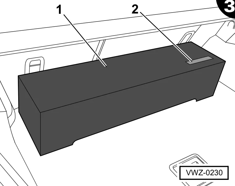
- Position the subwoofer -1- as close as possible to the backrest of the rear seat in the luggage compartment and press it firmly on the floor covering; in doing so, you must turn the subwoofer such that the emblem -2- points backwards (see also the safety instructions 2.0 operating instructions).
1.8 Final installation
- Secure the wiring harnesses and single wires of the sound system to existing wires or holders to avoid any rattling noises.
- Fit all vehicle parts in reverse order.
2.0 Operating instructions (information for the vehicle owner)
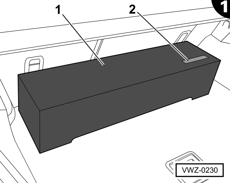
Shorting plug:
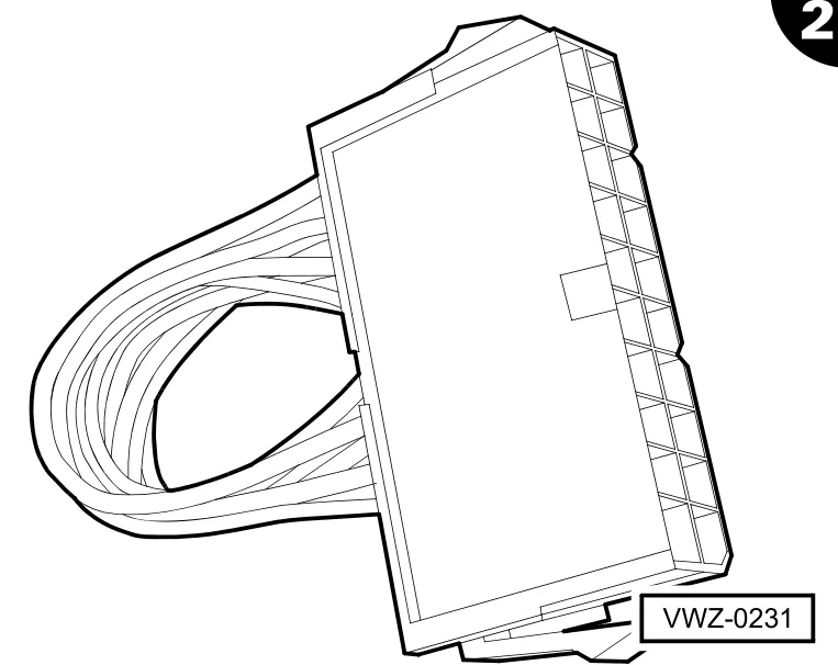
With the subwoofer/amplifier removed, the vehicle’s speakers do not work either. The vehicle speakers can be activated by fitting the shorting plug on the wiring harness’ amplifier connection.