
1.6 TDI CR engine (EA189) · Cylinder head, valve gear · Valve gear
Removing and installing valve stem seal
⇒ 3.7.1 Removing and installing valve stem seals with cylinder head installed
⇒ 3.7.2 Removing and installing valve stem seals with cylinder head removed
3.7.1 Removing and installing valve stem seals with cylinder head installed
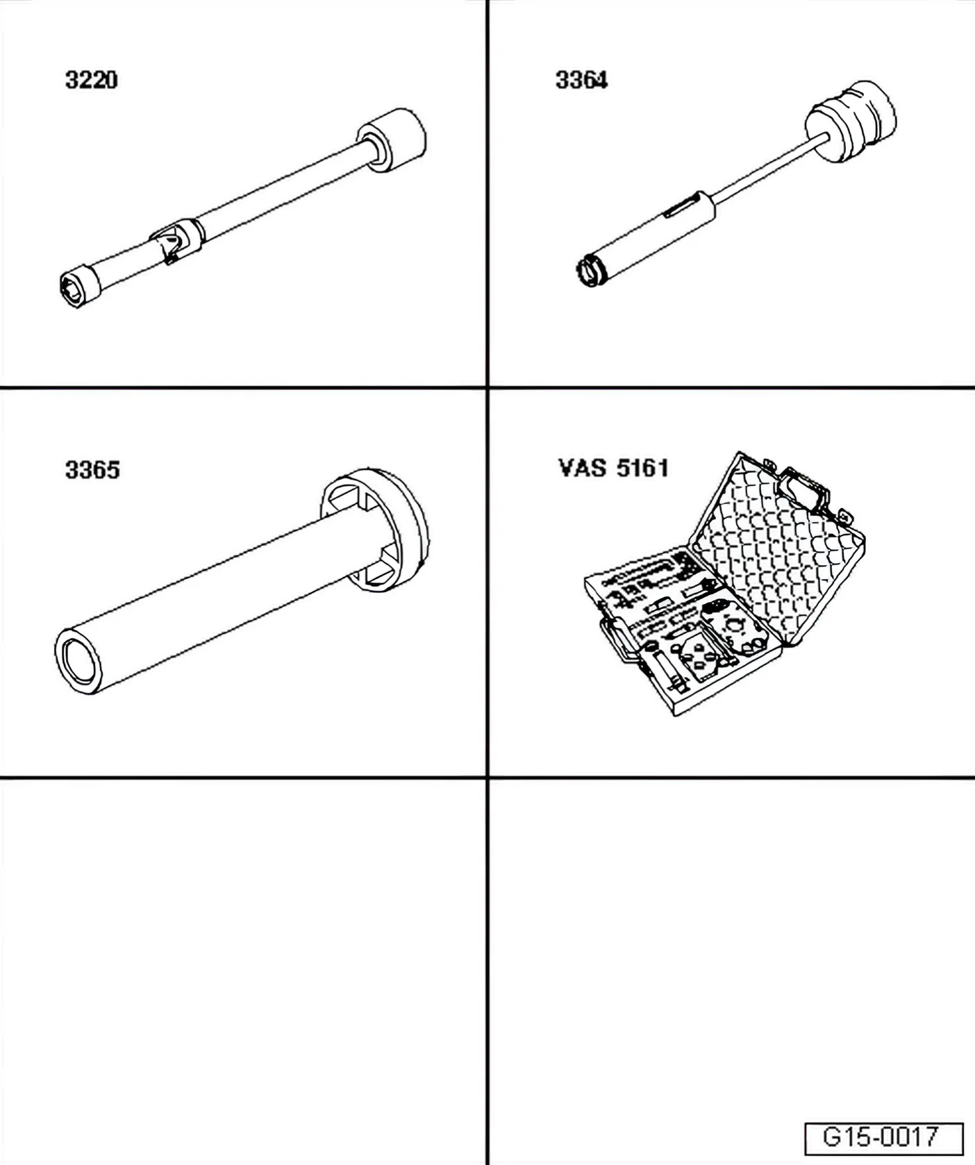
Special tools and workshop equipment required
- 10 mm jointed spanner - 3220-
- Valve stem seal puller - 3364-
- Valve stem seal fitting tool - 3365-
- Removal and installation device for valve cotters - VAS 5161- with guide plate - VAS 5161/23- and knurled spacer ring - VAS 5161/23-1-
Procedure
- Remove all glow plugs using U/J extension and socket - 3220- ⇒ 28 – Glow plug system.
- Remove camshafts ⇒ 3.5 Removing and installing camshaft.
- Remove roller rocker fingers; make a note of the installation position ⇒ Item 13 (3.1 Assembly overview - valve gear).
- Fit guide plate - VAS 5161/23- onto cylinder head.
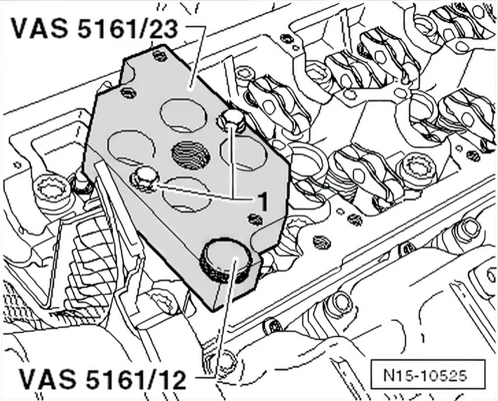
- Secure guide plate on intake manifold side with knurled screw - VAS 5161/12- and tighten hand-tight on studs using M6 collarless nuts -1-.
- Screw sealing pin - VAS 5161/10- into guide plate.
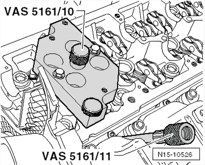
- Screw adapter - VAS 5161/11- hand-tight into glow plug hole of relevant cylinder.
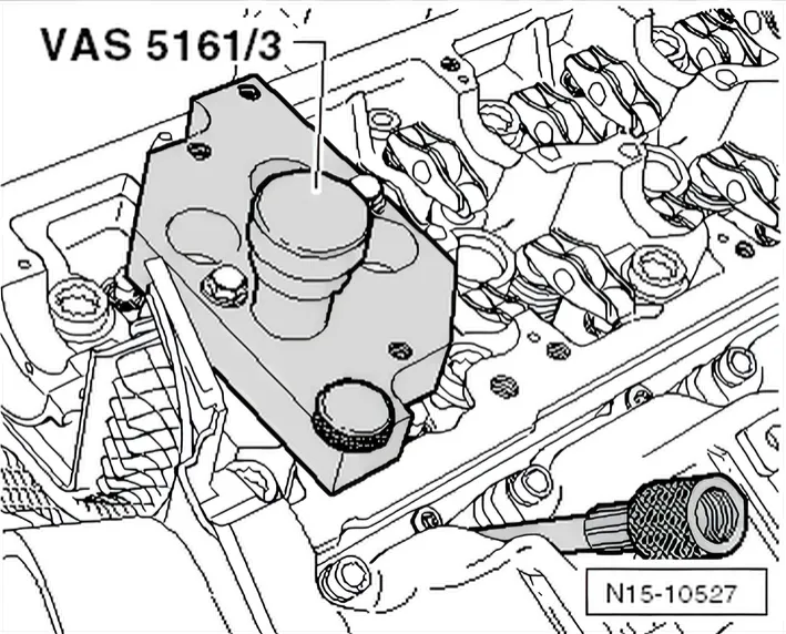
- Insert drift - VAS 5161/3- into guide plate and knock valve cotters loose using a plastic hammer.
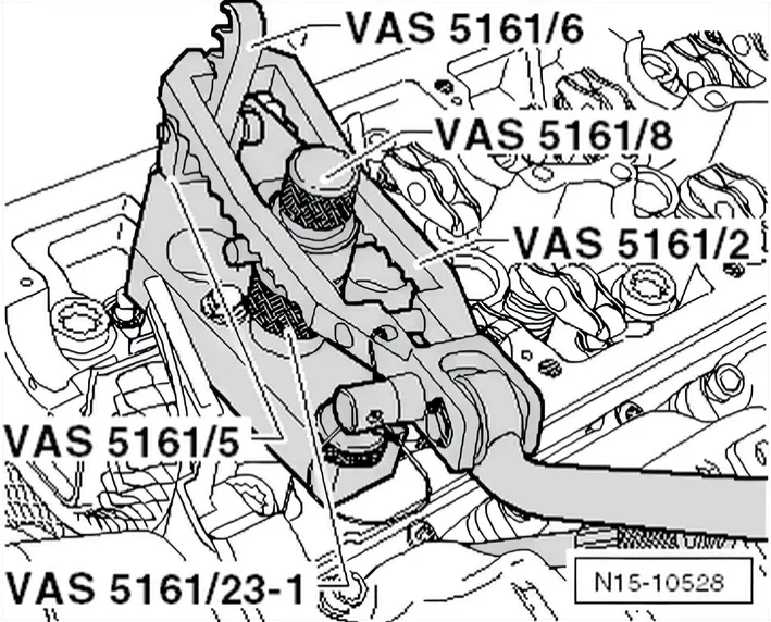
- Screw engaging fork - VAS 5161/5- with snap-in device - VAS 5161/6- into guide plate.
- Slide knurled spacer ring - VAS 5161/23-1- onto assembly cartridge - VAS 5161/8-.
- Connect adapter - VAS 5161/11- to compressed air line using a commercially available connection piece, and apply constant air pressure.
- Minimum pressure: 6 bar.
- Attach pressure fork - VAS 5161/2- to snap-in device and push assembly cartridge down.
- At the same time, turn knurled screw of assembly cartridge clockwise until tips engage in valve cotters.
- Move knurled screw back and forth lightly to press apart valve cotters and capture them in the assembly piece.
- Release pressure fork.
- Take out assembly cartridge with knurled spacer ring, valve plate and valve spring.
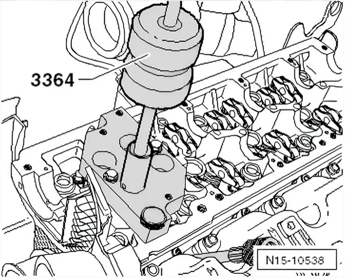
- Remove valve stem oil seals using valve stem seal puller - 3364-.
Installing
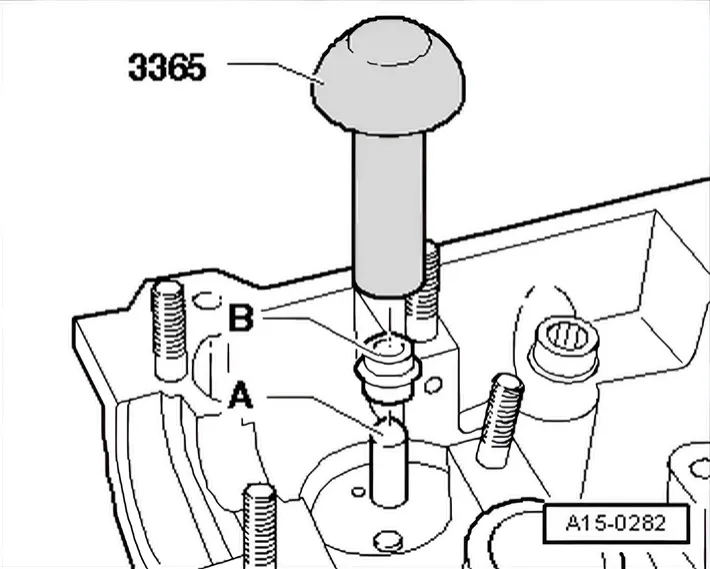
- Lightly oil sealing lip of valve stem oil seal and valve stem.
- Carefully push valve stem oil seal on valve stem -A-.
- Carefully press valve stem oil seal onto valve guide using valve stem seal fitting tool - 3365-.
- If necessary, use a plastic head hammer and tap lightly on fitting tool until valve stem oil seal is fitted to stop.
- Insert valve spring and valve spring plate into cylinder head.
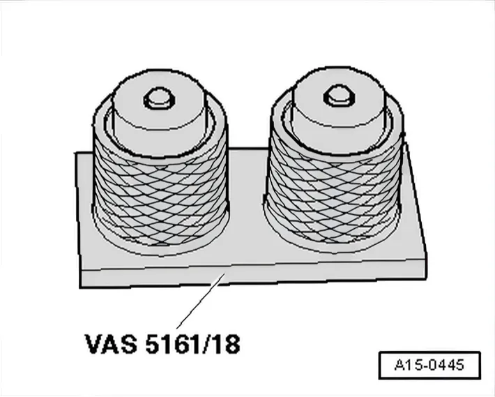
- If valve cotters have been removed from assembly cartridge, they need to be put into insertion device - VAS 5161/18- first.
- Press assembly cartridge onto insertion device from above and pick up valve cotters.
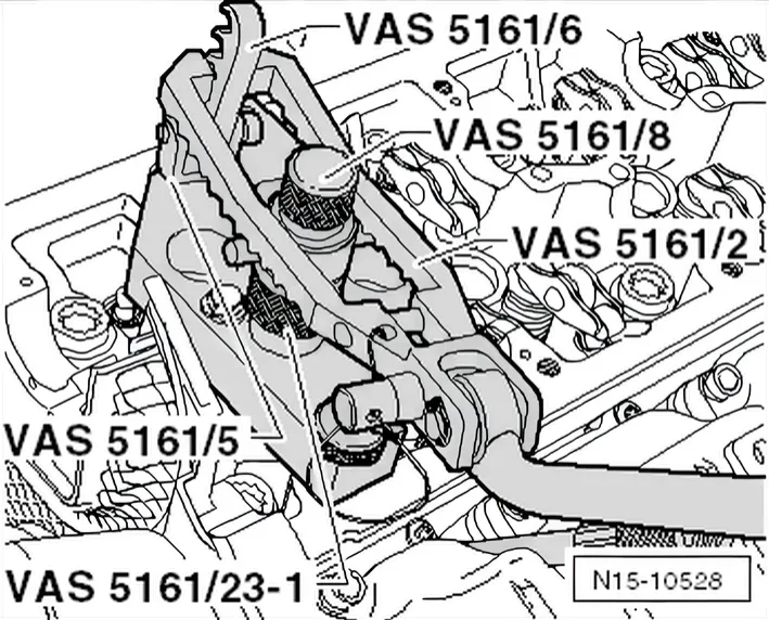
- Re-insert assembly cartridge - VAS 5161/8- into guide plate.
- Push pressure fork down, and pull knurled screw upwards while turning to left and right - this will insert the valve cotters.
- Release pressure fork with knurled screw still in pulled position.
Further installation is carried out in reverse order; note the following:
- Install camshafts ⇒ 3.5 Removing and installing camshaft.
- Install glow plugs ⇒ 28 – Glow plug system.
3.7.2 Removing and installing valve stem seals with cylinder head removed
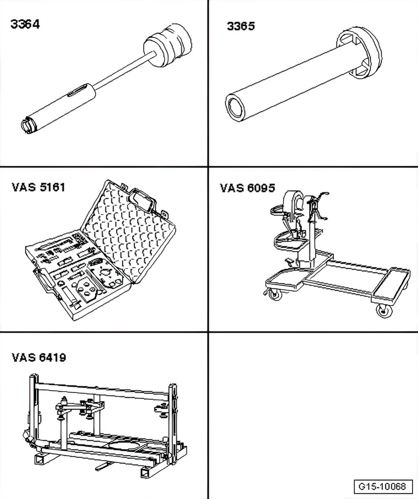
Special tools and workshop equipment required
- Valve stem seal puller - 3364-
- Valve stem seal fitting tool - 3365-
- Removal and installation device for valve cotters - VAS 5161- with guide plate -VAS 5161/23- and sleeve -VAS 5161/23-1-
- Engine and gearbox support - VAS 6095-
- Cylinder head tensioning device - VAS 6419-
- Bolt M6×30 (qty. 2)
Procedure
- Remove camshafts ⇒ 3.5 Removing and installing camshaft.
- Mark allocation of roller rocker fingers and hydraulic compensation elements for reinstallation.
- Remove roller rocker fingers together with hydraulic compensation elements and place down on a clean surface.
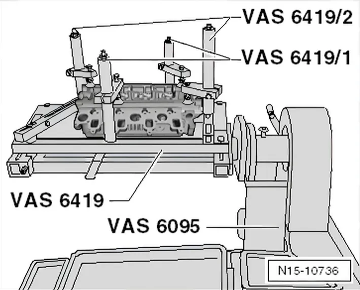
- Insert cylinder head tensioning device - VAS 6419- into engine and gearbox support - VAS 6095-.
- Clamp cylinder head in cylinder head clamping device as shown in illustration.
Operating instructions for the cylinder head tensioning device - VAS 6419- are enclosed with unit.
- Connect cylinder head tensioning device to compressed air.
- Use lever -arrow- to slide air cushion under combustion chamber from which valve stem seal is to be removed.
- Allow compressed air to flow into air cushion until it lies against valve disc.
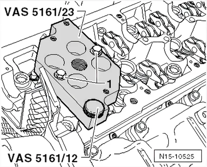
- Place guide plate -VAS 5161/23- onto cylinder head.
- Tighten guide plate on intake manifold side by hand using knurled screw -VAS 5161/12- and 2 M6x30 bolts until it makes contact.
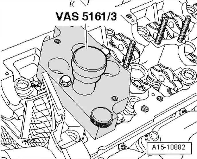
- Insert drift -VAS 5161/3- into guide plate and use a plastic hammer to knock loose the firmly seated valve cotters.
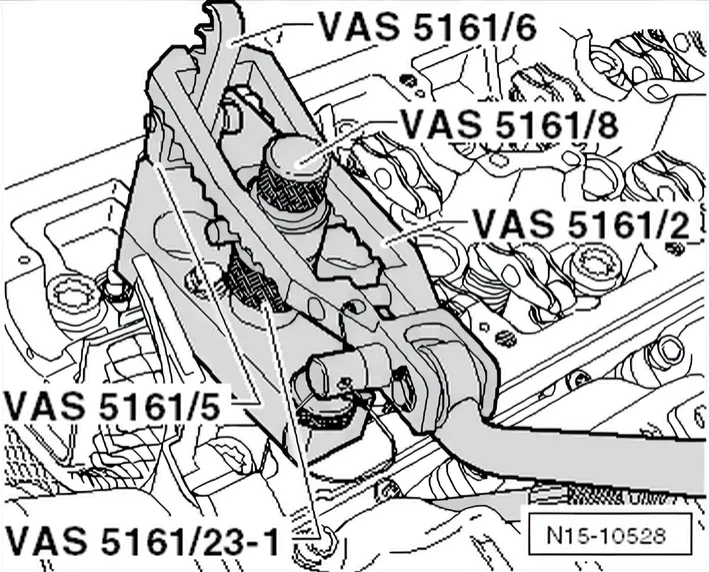
- Screw toothed piece -VAS 5161/6- with hooking fork - VAS 5161/5- into guide plate.
- Push sleeve -VAS 5161/23-1- onto assembly cartridge - VAS 5161/8-.
- Attach pressure fork -VAS 5161/2- to toothed piece and press assembly cartridge down.
- At the same time, turn knurled screw of assembly cartridge clockwise until tips engage in valve cotters.
- Move knurled screw back and forth to press apart valve cotters and capture them in assembly cartridge.
- Release pressure fork.
- Remove assembly cartridge with knurled spacer ring.
- Remove valve spring and valve spring plate.
- Pull off valve stem seal using valve stem seal puller - 3364-.
- Lightly oil sealing lip of valve stem oil seal and valve stem.
- Carefully push valve stem oil seal on valve stem -A-.
- Carefully press valve stem oil seal onto valve guide using valve stem seal fitting tool - 3365-.
If the valve cotters have been removed from the assembly cartridge, they must first be inserted into the valve insertion device - VAS 5161/18-.
- Larger diameter of valve cotters faces upwards.
- Insert valve spring and valve spring plate.
- Press assembly cartridge onto valve insertion device from above and pick up valve cotters.
- Insert assembly cartridge into guide plate -VAS 5161/23- again.
- Press pressure fork downwards and pull knurled screw upwards, turning it clockwise and anticlockwise. This inserts the valve cotters.
- Reduce pressure on pressure fork whilst pulling on knurled screw.
- Repeat procedure on each valve.
Installing
Installation is carried out in the reverse order; note the following:
- Ensure that all roller rocker fingers contact valve stem ends correctly and are clipped into relevant hydraulic compensation elements.
- Install camshafts ⇒ 3.5.2 Installing.