
Workshop manual · VW Polo 6R
1.4 MPI engine (EA111)
Workshop manual for the VW Polo 6R 1.4 MPI engine, code CGGB (EA111), procedure by procedure: removal, crankshaft group, cylinder head, toothed belt drive, lubrication, cooling, fuel supply, injection, exhaust and ignition, with torque settings. The older engine codes of the Polo 2002 are in the PDF.
- 86 procedures
- 236 drawings
- 153 torques
No procedure matches your search.
Most common jobs
Repair groups
- Technical dataEngine number and engine data1 procedure
- Removing and installing engineRemoving and installing the engine, assembly mountings7 procedures
- Crankshaft groupPoly V-belt drive, cylinder block, crankshaft, pistons and conrods18 procedures
- Cylinder head, valve gearCylinder head, toothed belt, camshaft housing and valve gear14 procedures
- LubricationEngine oil, sump, oil pump and oil pressure6 procedures
- CoolingCoolant, coolant pump, radiator and coolant hoses7 procedures
- Fuel supply systemFuel tank, fuel delivery unit, fuel pump check and activated charcoal filter12 procedures
- Mixture preparation – injectionIntake manifold, injectors, throttle valve module, air filter and control unit13 procedures
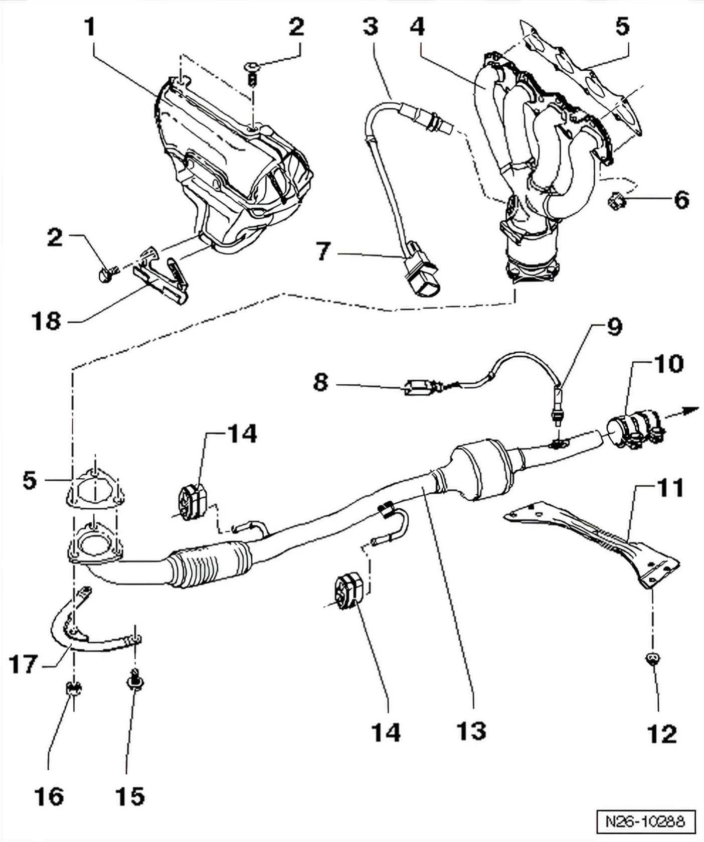
- Exhaust systemExhaust manifold, front exhaust pipe and silencers3 procedures
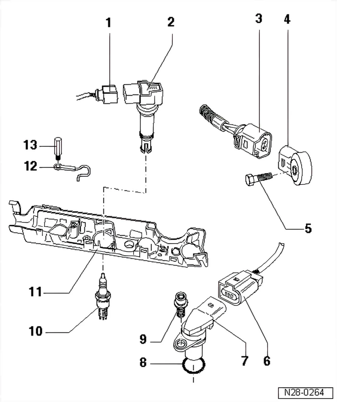
- Ignition systemIgnition coils, knock sensor, Hall sender and spark plugs5 procedures
Removing and installing engine
7 procedures
Group page →Crankshaft group
18 procedures
Group page →Dismantling and assembling engine
Cylinder block, sealing flange
- Assembly overview
- Pulling needle bearing out of and driving into crankshaft
- Renewing crankshaft oil seal – belt pulley end
- Poly V-belt pulley securing bolt tightening procedure
- Removing and installing drive plate
- Characteristics of the sealing flange and the assembly device T10017 and T10134
- Renewing crankshaft sealing flange – flywheel end ( assembly tool T10134 )
- Renewing crankshaft sealing flange – flywheel end ( assembly tool T10017 )
- Crankshaft dimensions
Pistons and conrods
Lubrication
6 procedures
Group page →Cooling
7 procedures
Group page →Fuel supply system
12 procedures
Group page →Mixture preparation – injection
13 procedures
Group page →Injection system
- General notes on injection
- Assembly overview – parts of injection system Diagram
- Assembly overview – intake manifold Diagram
- Assembly overview – fuel rail with injectors Diagram
- Assembly overview – air filter Diagram
- Removing and installing air filter housing
- Cleaning throttle valve module J338
- Checking injectors
- Safety precautions
- Rules for cleanliness
- Technical data