Fitting the genuine roof bars to the Volkswagen Polo from 2009 (6R0 071 126 and 6R3 071 126): safety information, parts list, installation, width adjustment and technical data.
Roof bars
Part number:
6R0 071 126
Vehicle:
Polo 2009– (6R)
Dear Customer,
Thank you for choosing this original Volkswagen accessory. Please carefully follow the steps described in these instructions and heed all Warnings as well as safety information in this booklet.
Safety information
Precautions to help prevent damage to your vehicle
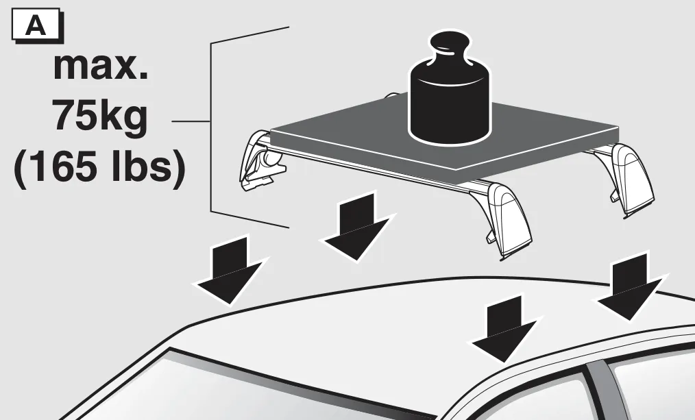
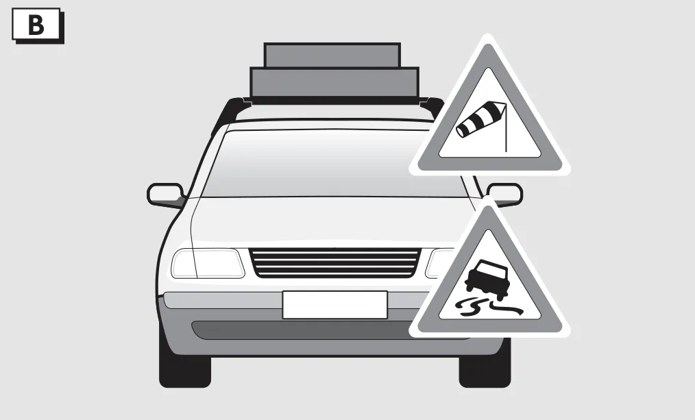
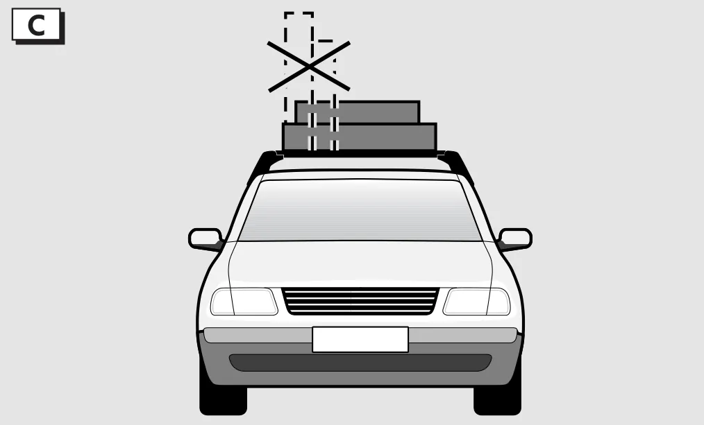
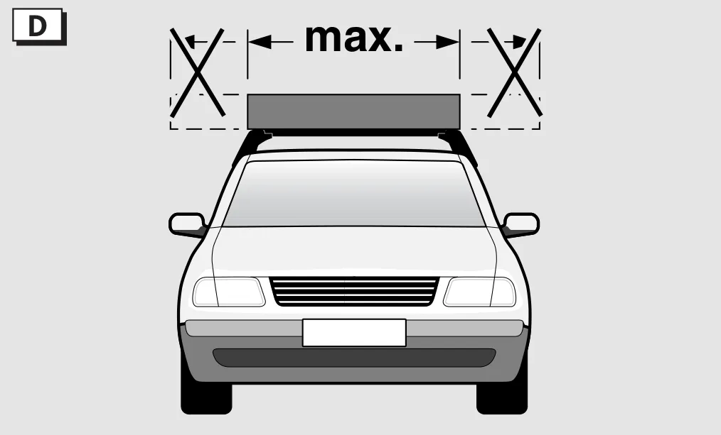
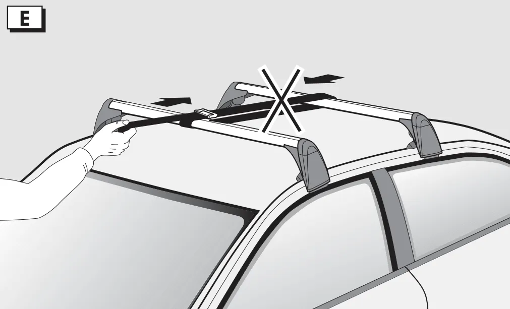
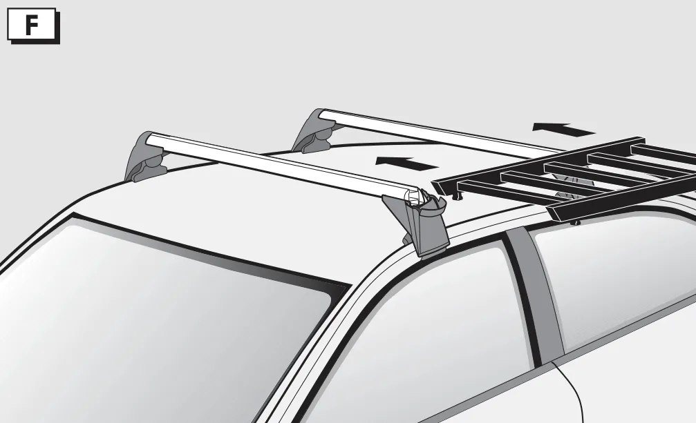
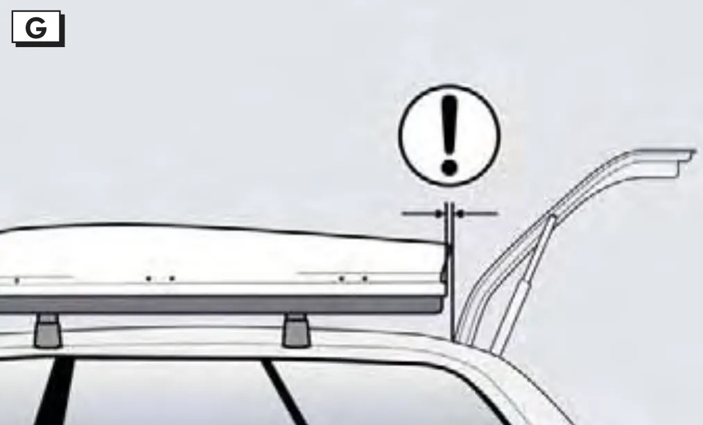
Figure A: maximum roof load 75 kg (165 lbs)Figure B: a roof load changes the handling: crosswinds, slippery roadsFigure C: distributing the loadFigure D: no load wider than the roof barsFigure E: never tie the bars together under tensionFigure F: fit attachments only to properly installed barsFigure G: the load must not block the tailgate or the sunroof
Scope of delivery
Scope of delivery
Item
Designation
Qty
1
Front carrier unit
1
2
Rear carrier unit
1
3
Profiled cover
1
4
Torque wrench
1
5
Installation instructions
1
Front carrier unit (1), rear carrier unit (2), profiled cover (3), torque wrench (4), installation instructions (5)
Parts list
Parts list
Item
Designation
Qty
1
Tubular section, front
1
2
Tubular section, rear
1
3
Sliding block
4
4
Supporting foot cover
4
5
Screw cover
8
6
Screw M6x16
8
7
Supporting foot, FL
1
8
Supporting foot, FR
1
9
Supporting foot, RL
1
10
Supporting foot, RR
1
11
Screw 4x8
8
12
Tensioning clamp, FL
1
13
Tensioning clamp, FR
1
14
Tensioning clamp, RL
1
15
Tensioning clamp, RR
1
16
Coded tensioning bolt
4
17
Washer, steel
4
18
Sleeve, steel
4
19
Cover cap
4
20
Cover plate
4
21
Screw 2.5x5
4
22
Moulded cap
4
23
Cover section
2
24
Torque wrench
1
25
Fitting instructions
1
26
Front left type sticker
1
27
Rear left type sticker
1
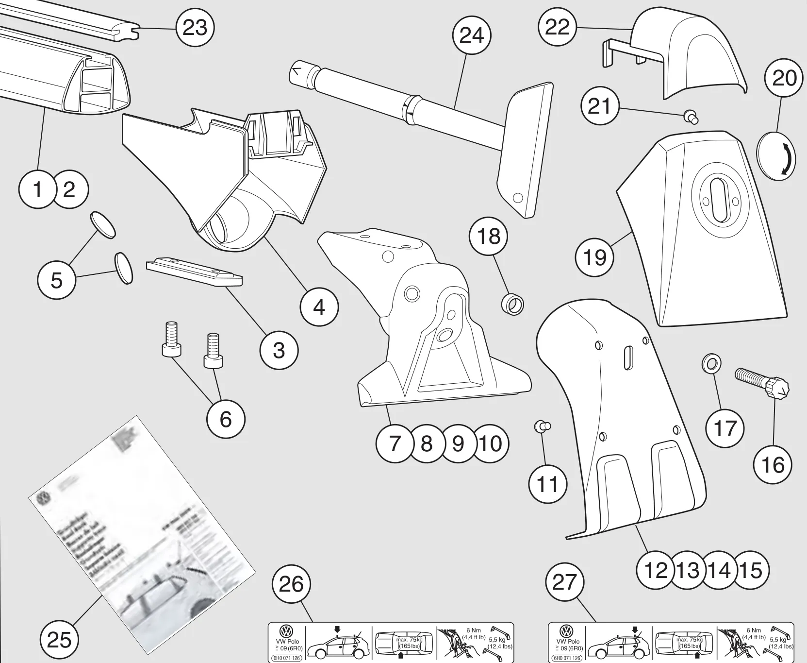
Roof bar parts, numbered as in the parts list
Installing on the vehicle roof
Figure 1
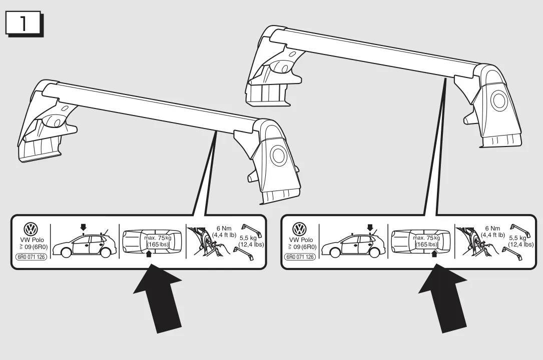
The left underside of the tubular sections have stickers for the front or rear. When installing the roof carrier system, always make sure that the stickers are located on the left-hand side of the vehicle.
Figure 1: front and rear stickers on the left side of the bars
Figure 2a
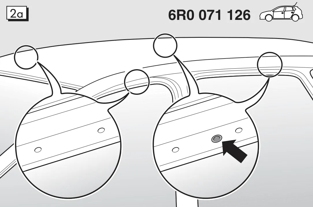
The roof carrier bars may only be installed at the positions as marked, the roof is reinforced at these locations especially for this roof carrier system. On the underside of the side frame at the rear there is one hole between the marks for this purpose. At the front there are two marks.
Figure 2a: mounting points on the roof, 6R0 071 126
Figure 2b
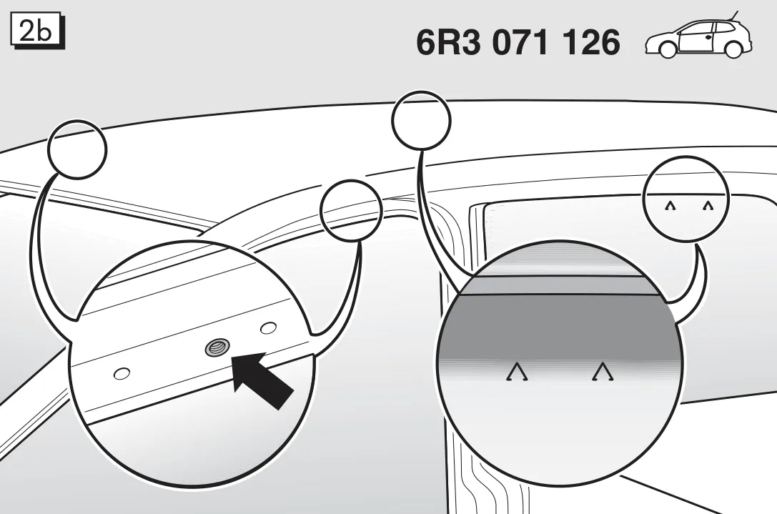
The front roof carrier bars are installed as per the rear bars referring to Fig. 2a. The tensioning clamps for the rear roof carrier bars are secured on the vehicle between the marks on the window.
Figure 2b: mounting points on the roof, 6R3 071 126
Figure 3
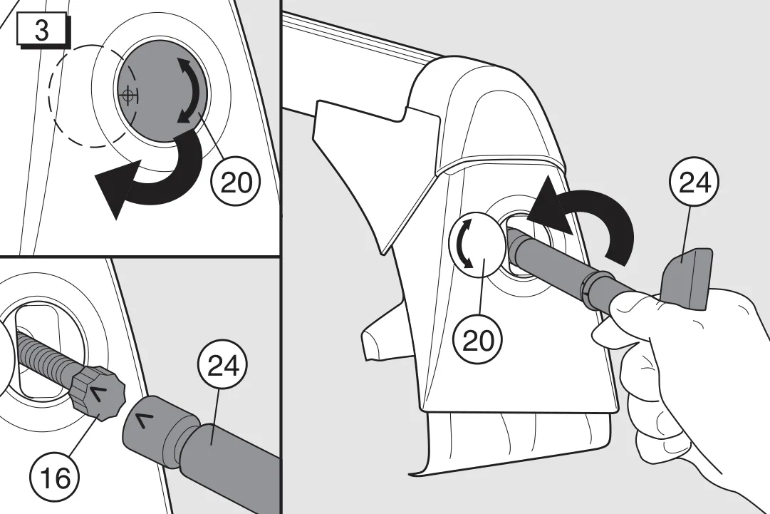
Swing cover plate (20) sideways in a circular movement. Fit torque wrench (24) onto tensioning bolt (16) in direction of arrow. The arrow on the torque wrench must align with the arrow on the tensioning bolt. Loosen tensioning bolt about 20 turns.
Figure 3: cover plate (20) swung aside, tensioning bolt (16) loosened with the torque wrench (24)
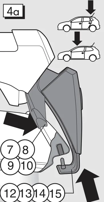
Figure 4a
Position the supporting feet (7, 8, 9, 10) on the edge of the roof. From below, guide pin into prescribed hole. Push tensioning clamps (12, 13, 14, 15) upwards and tighten tensioning bolts (16) lightly.
Figure 4a: supporting feet (7–10) on the roof edge, tensioning clamps (12–15) from below
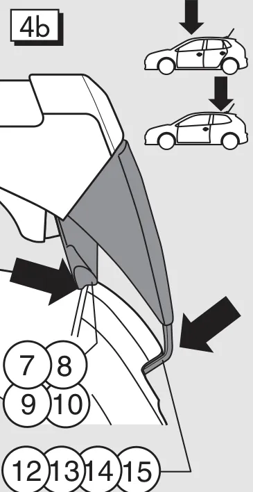
Figure 4b
The roof carrier system is installed as per Fig. 4A. Position the roof carrier system with the supporting feet (7, 8, 9, 10) on the edge of the roof and position the tensioning clamps (12, 13, 14, 15) between the prescribed marks.
Figure 4b: the other bar as in Figure 4a
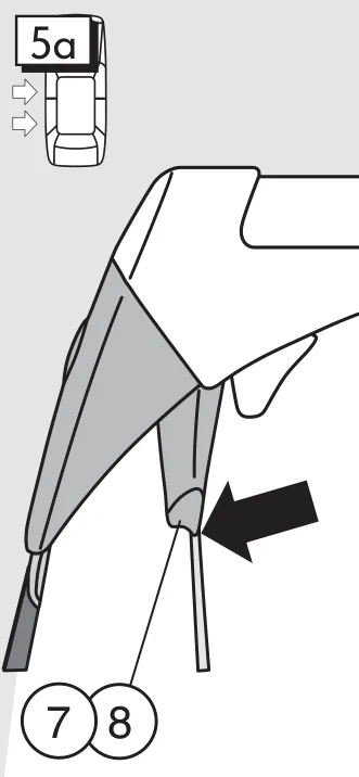
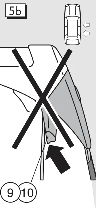
Figure 5 a, b, c, d
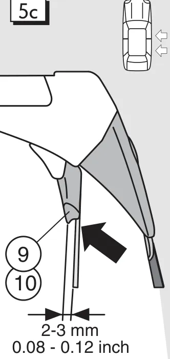
Align the roof carrier system so that the left supporting feet lie on the edge of the roof (see Fig. 5a). Lightly tighten the left tensioning clamps to prevent the roof rack system slipping. Lightly tighten all tensioning bolts (16) using torque wrench (24).
Figure 5a: left supporting foot on the roof edgeFigure 5b: incorrectFigure 5c: right supporting foot 2–3 mm from the roof edge: correctFigure 5d: more than 3 mm: incorrect
Figure 6
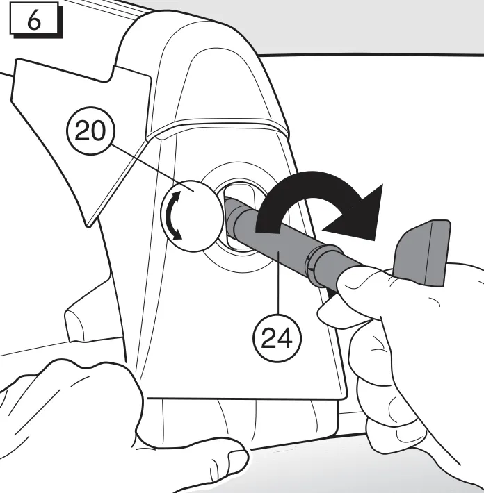
Alternately tighten the tensioning bolts (16) on the left and right sides in two stages to 6 Nm using torque wrench (24). Both arrows on the torque wrench (24) must be directly opposite one another (6 Nm).
Figure 6: tightening the tensioning bolts (16) to 6 Nm with the torque wrench (24)
Figure 7
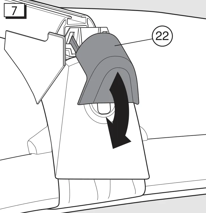
To install attachments, open the moulded cap (22) and insert the attachment in the T-groove. Close the moulded cap again.
Figure 7: moulded cap (22) opened
Figure 8
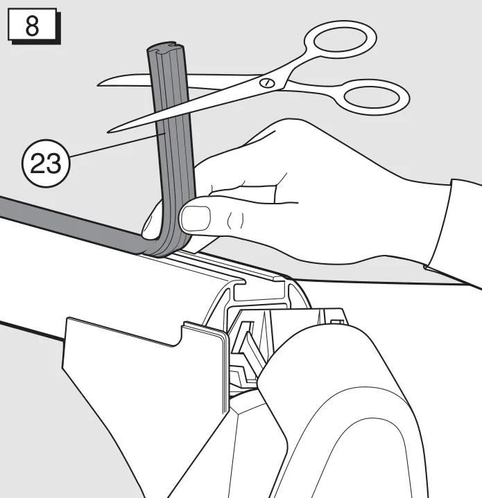
If attachments are not used, close the T-groove with the cover section (23) by adjusting the cover section to the length of the carrier system.
Figure 8: cover section (23) cut to the bar's length
Adjusting the roof bar width
Nore for the dealer, if, as described under Fig. 5c, the position of the support foot for the particular vehicle is not correctly set.
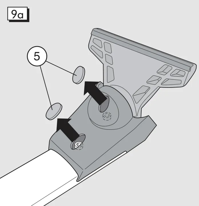
Figure 9a
Remove the two plastic caps (5) on the underside of the roof bar.
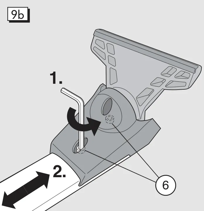
Figure 9b
Use a allen key (metric size 5) to loosen the two bolts (6) until the foot can be moved.
Adjust the roof bar to the correct width (page 17).
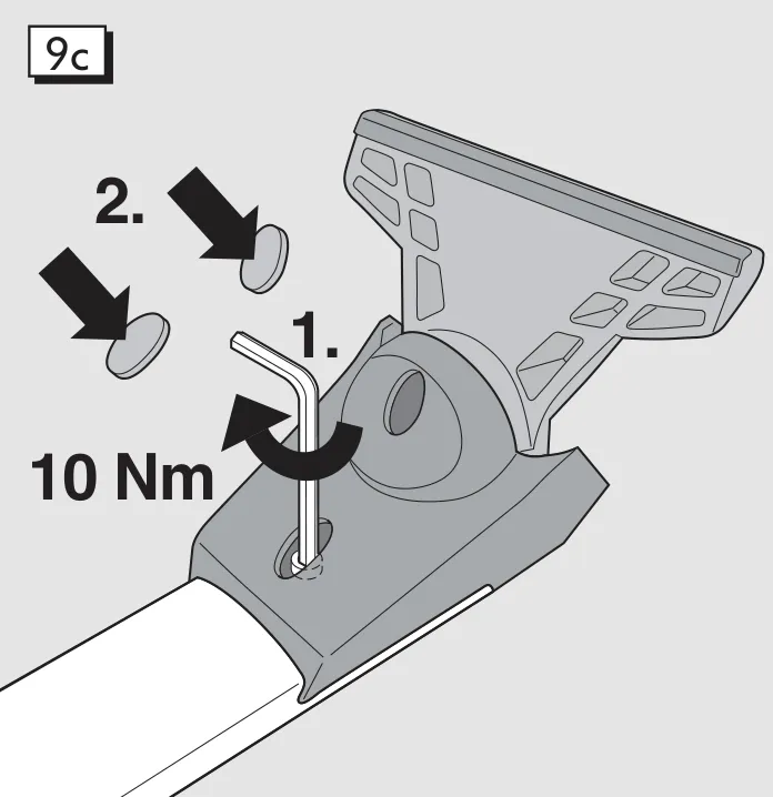
Figure 9c
Tighten the two bolts (6) to 10 Nm. Fit the roof bar to the vehicle and check the accuracy of the fit.If the fit does not correspond to that described on page 17, it may be necessary to repeat the adjustment.
Fit plastic caps (5).
Figure 9a: removing the plastic caps (5)Figure 9b: loosening the bolts (6) and moving the footFigure 9c: tightening the bolts (6) to 10 Nm and refitting the caps
Technical data
Weight of roof bars/ suppporting rod set: approximately. 12,1 lb (5,5 kg)
Usable length of profile: Front 39,3 inch (1000 mm) Rear 38,4 inch (975 mm)
Determining the actual roof load:
Weight of roof rack bars/supporting rods
+ Weight of attachments + Weight of cargo on roof rack = Actual roof load
Care instructions:
Keep the roof bars clean and well maintained at all times, particularly in winter when dirt and salt should be removed at regular intervals to help prevent damage.
For the sake of the environment:
Often the roof bars/supporting rods with/without attachments are left on the vehicle for convenience, even when not needed. The increased wind resistance unnecessarily increases fuel consumption and generates additional noise. Therefore, remove roof rack bars/supporting rods and any attachments when not in use.