Side sill set 6R0071685GRU

Fitting the side sills on the Volkswagen Polo from 2009: preparation, trial fitting, painting, bonding and curing times.

Side sill set

Part number:
6R0 071 685 GRU
Vehicle:
Polo 2009– (6R)

Please read fitting instructions thoroughly before commencing installation.

We recommend that fitting is carried out by a specialist workshop.

Recommendation: If possible an access stage is to be used for fitting the side skirts!

It is recommended that fitting is carried out by two people.

The body part is precision manufactured and preprimed. However, trial fitting should still be carried out in accordance with these fitting instructions before painting.

Note: Further information regarding removal / fitting of respective parts can be found in repair guide “General body repairs, exterior”.

When a jack is used, ensure that the side sills are not damaged!

Scope of delivery

Side sill set: side sills (1), covers (2), brackets and fixings; the adhesive kit 000 071 785 A (17–20) is ordered separately
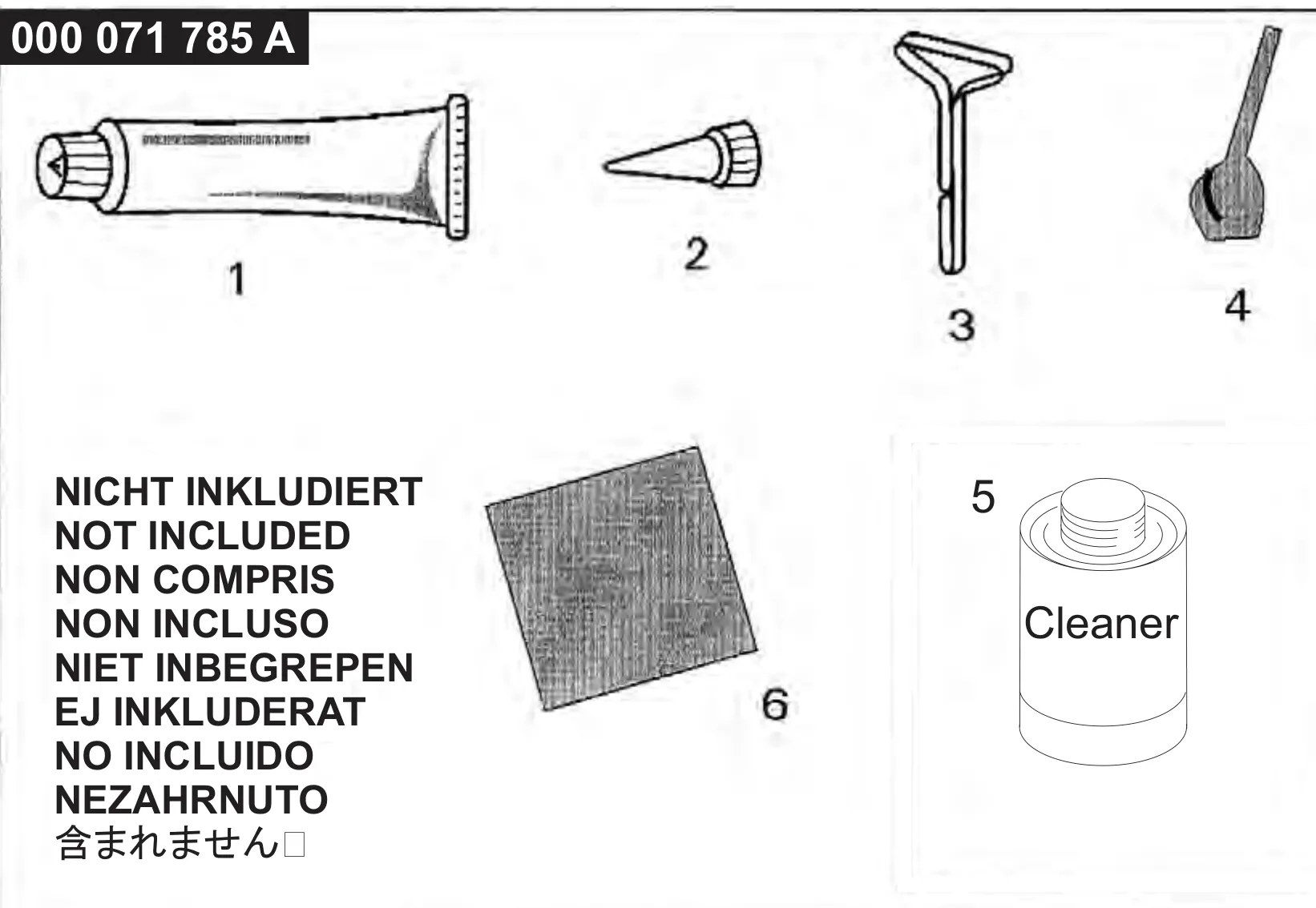
Elch adhesive and cleaning kit 000 071 785 A (not included)

Painting

Guidelines for working with primed PU RIM components

Rubbing downWet P 600
Base paintQuality Herberts:
Corresponds to: LMT 626 / ALD 626 UNI pore filler
LMT 845 / ALD 645 metallic pore filler
LPC 045 / ALD 045 pearl colour pore filler
Viscosity20 sec.
Spray applications2
Coat thicknessapprox. 20 μm
Ventilation time10 min.
Final ventilation time15 min.
Spray gunDevilbiss GTI 1.4 mm
Clear lacquerQuality Herberts:
Corresponds to: 2-component MS clear lacquer NEW
L2K 769 011 + 10% softener
2 : 1 +10% thinner
Viscosity18 sec.
Spray applications2
Coat thicknessapprox. 50 μm
Ventilation time10 min.
Dryingovernight at 20 °C
Spray gunDevilbiss GTI 1.4 mm

Preparation

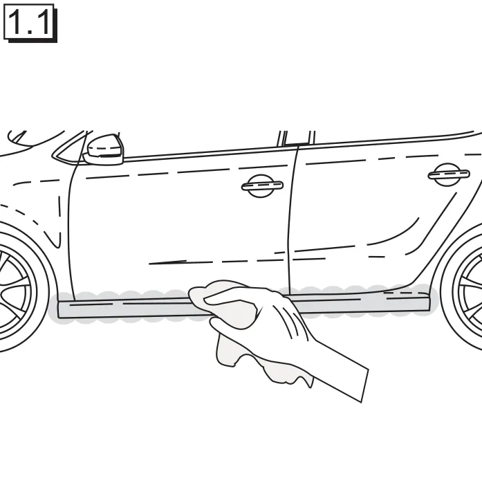
Figure 1.1
1.1 Clean the vehicle thoroughly in the side sill (1) fitting area.
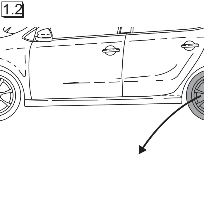
Figure 1.2
1.2 Remove rear tyres.
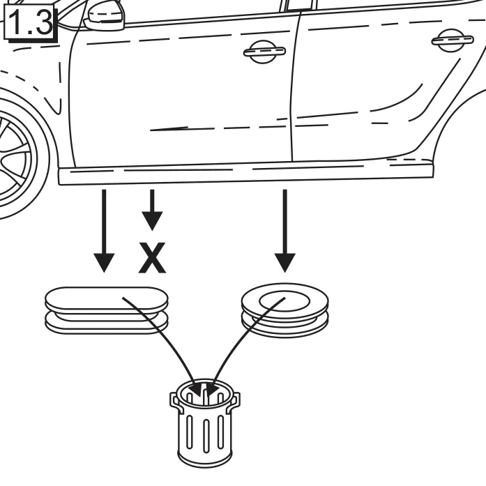
Figure 1.3
1.3 Remove the rubber cap in the front and centre area on the underside of the vehicle.
Figure 1.4
1.4 Remove the original screw from the underside of the vehicle. This screw will be required again later.
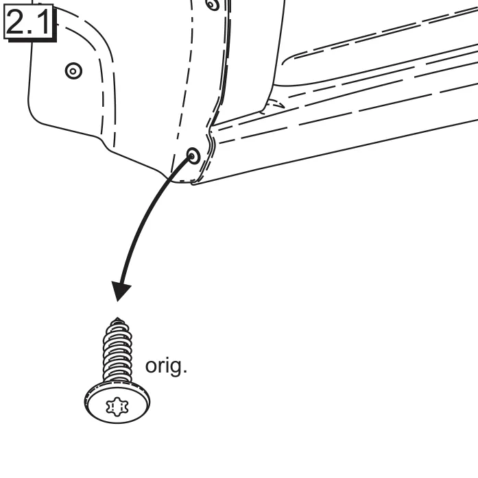
Figure 2.1
2.1 Remove the original screw in the front wheelhouse. This screw will be required again later.
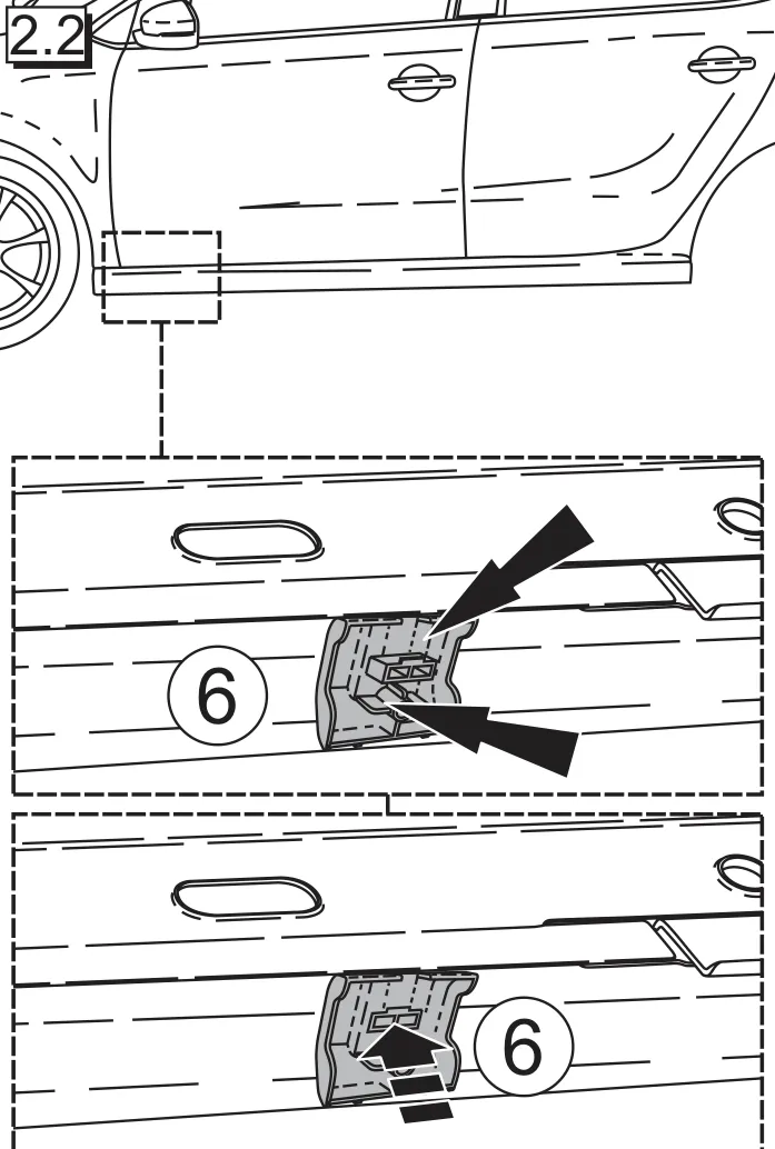
Figure 2.2
2.2 Position the attachment element (6) in the front area of the vehicle and then press the fixing button.
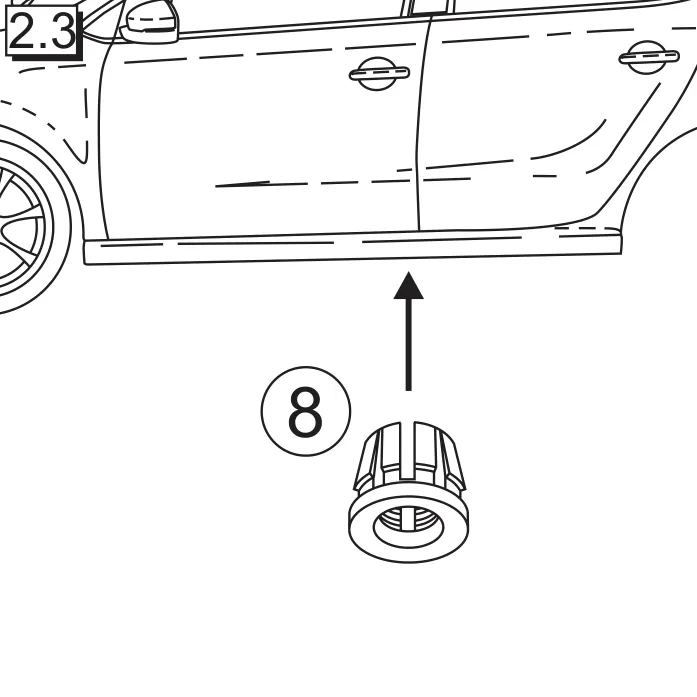
Figure 2.3
2.3 Press the plastic clip (8) in the central area.
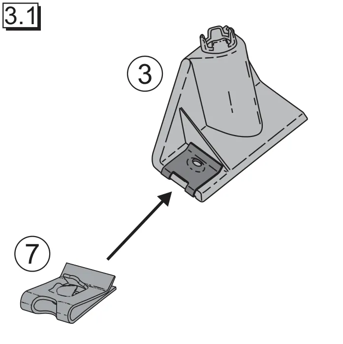
Figure 3.1
3.1 Insert the metal plate (7) on the front bracket (3).
Figure 3.2
3.2 Insert the metal plate (7) on the centre bracket (4).
Figure 3.3
3.3 Insert the metal plate (7) on the rear bracket (5).
Figure 4.1
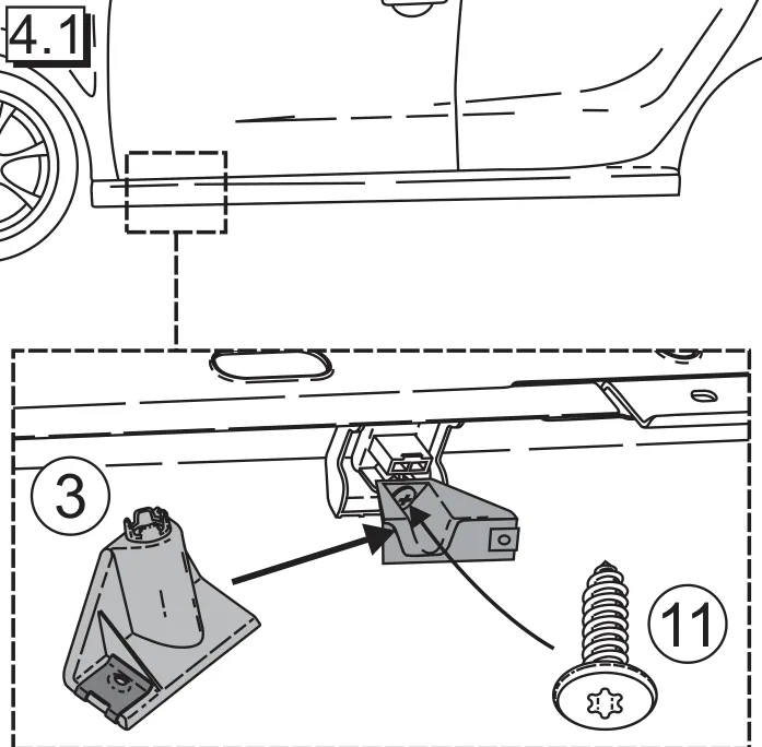
4.1 Position the front bracket (3) in the front area and screw tight using the screw (11).
Figure 4.2
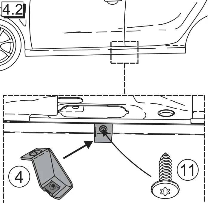
4.2 Position the centre bracket (4) in the central area and screw tight using the screw (11).
Figure 4.3
4.3 Position the rear bracket (5) in the rear area and screw in place using the original screw.
Figure 5.1
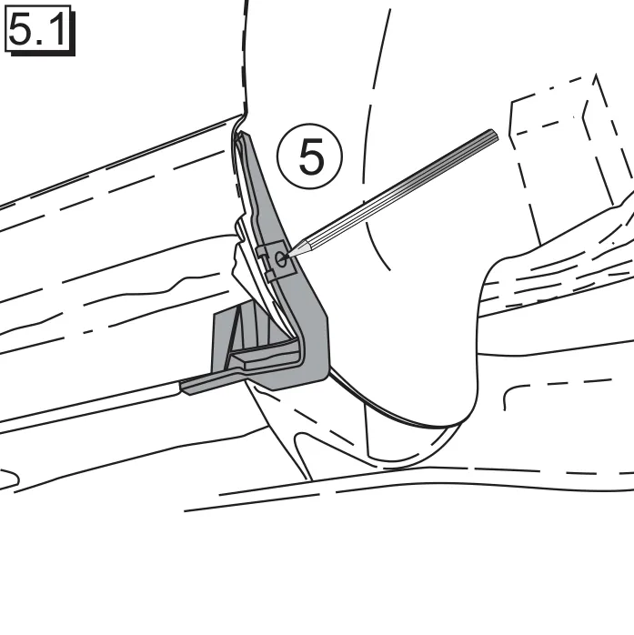
5.1 Mark the bore hole in the rear wheel arch.
Figure 5.2
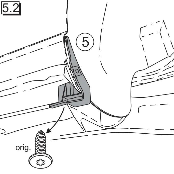
5.2 Remove the screw. Then remove the centre bracket (4).
Figure 5.3
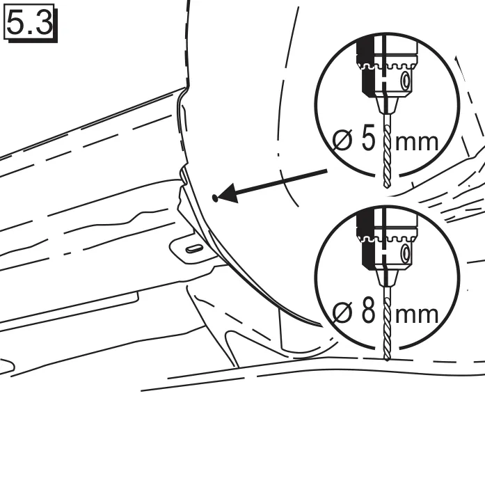
5.3 Drill open at the marking using a 5mm drill and then using an 8 mm drill.
Figure 5.4
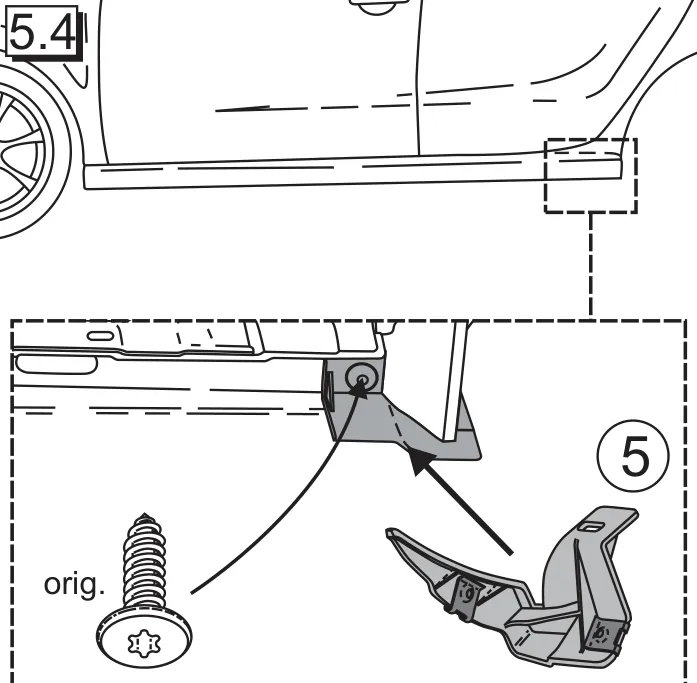
5.4 Position the rear bracket (5) in the rear area and screw in place using the original screw.

Trial fitting
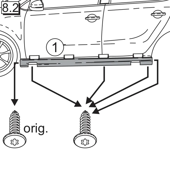
Figure 6.1
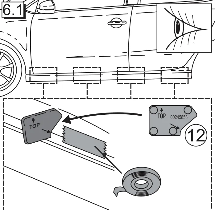
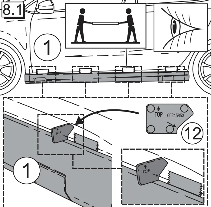
6.1 Position the template (12) as shown in the sketch and mark the exact position using adhesive tape.
Figure 6.2
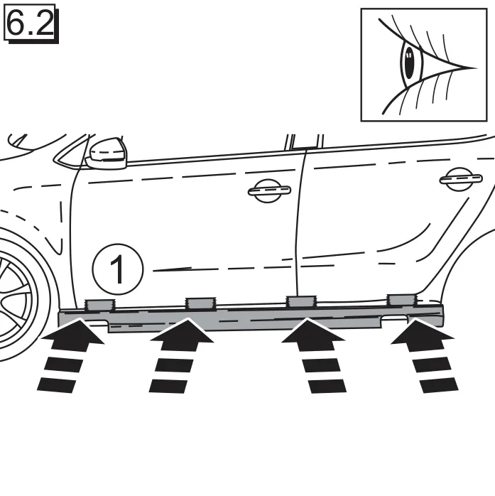
6.2 Position the side sill (1).
Figure 6.3
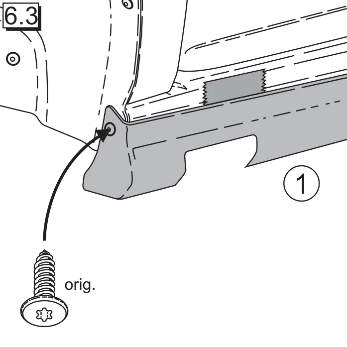
6.3 Screw the side sill (1) in the front wheelhouse using the original screw.
Figure 6.4
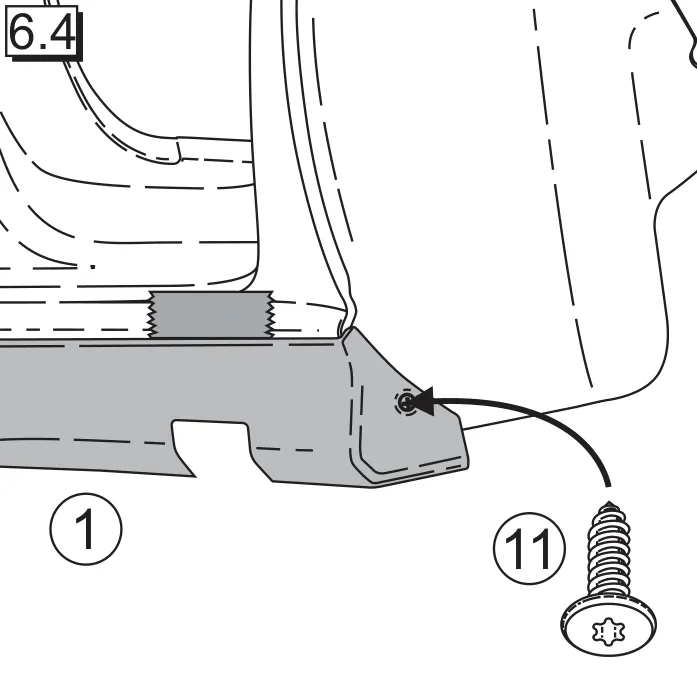
6.4 Screw the side sill (1) in the rear wheelhouse using the screw (11).
Figure 7.1
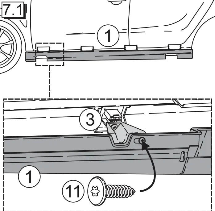
7.1 Screw the side sill (1) to the front bracket (3) in the front area using the screw (11).
Figure 7.2
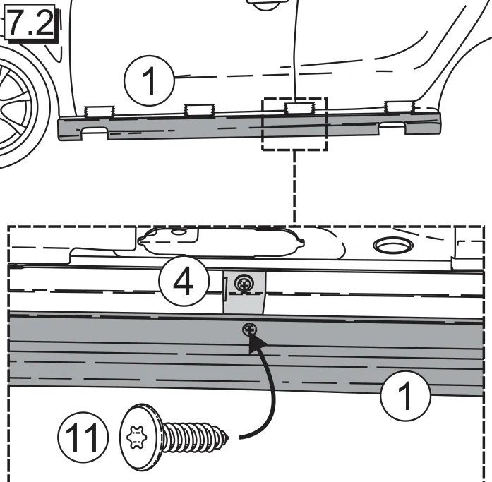
7.2 Screw the side sill (1) to the centre bracket (4) in the centre area using the screw (11).
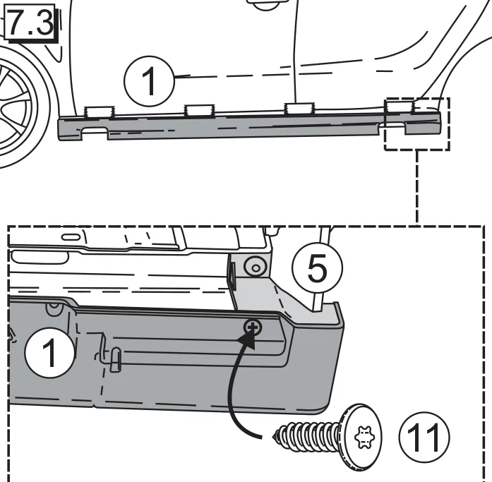
Figure 7.3
7.3 Screw the side sill (1) to the rear bracket (5) in the rear area using the screw (11).
Figure 8.1
8.1 Use the template (12) to check the correct position of the side sill (1).
Figure 8.2
8.2 Remove the screws.
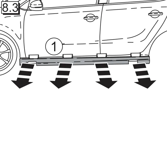
Figure 8.3
8.3 Remove the side sill (1).

Fitting

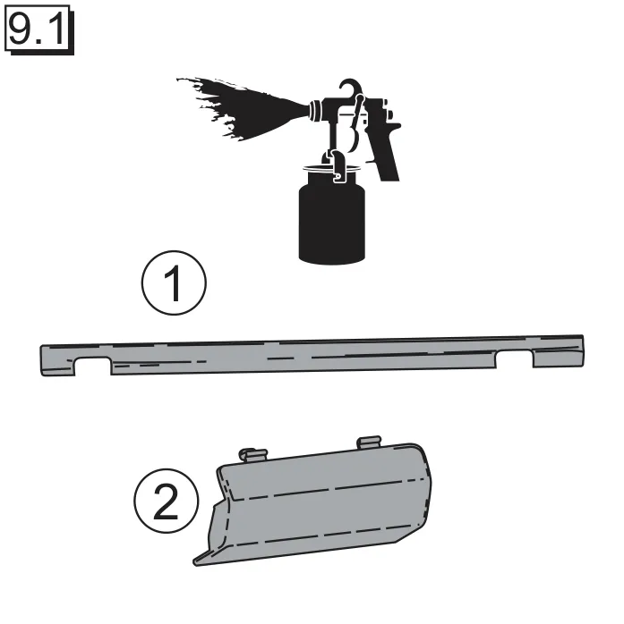
Figure 9.1
9.1 Paint the side sill (1) and cover (2) according to the enclosed painting instructions (15). Note: The adhesive surfaces must not be painted, they must remain free of paint and paint mist.
Figure 9.2
9.2 Insert the metal clip (10) on the inside of the cover (2).
Figure 9.3
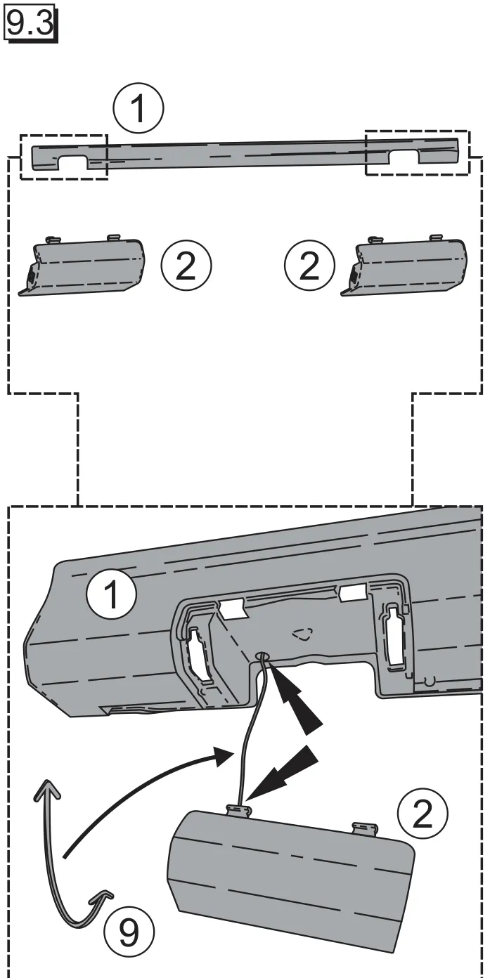
9.3 Thread the check strap (9) on the side sill (1) and on the cover (2) as shown in the sketch.
Figure 10.1
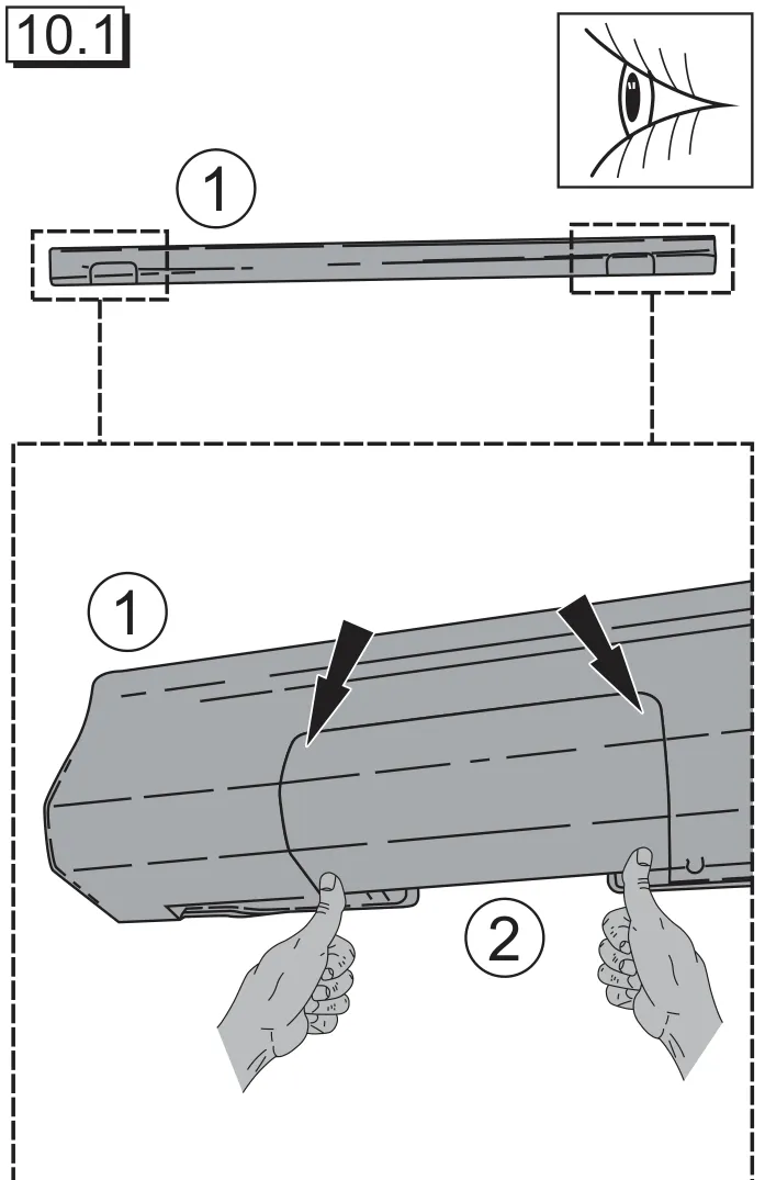
10.1 Insert the cover (2) in the recess at the top of the side sill (1) and then clip it downwards. Note: Make sure the metal clip (10) is fitted correctly!
Figure 10.2
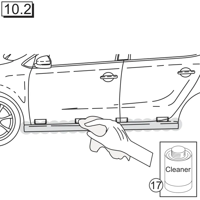
10.2 Clean the vehicle thoroughly with cleaner (17) in the area where the side sill (1) is to be fitted.
Figure 11.1
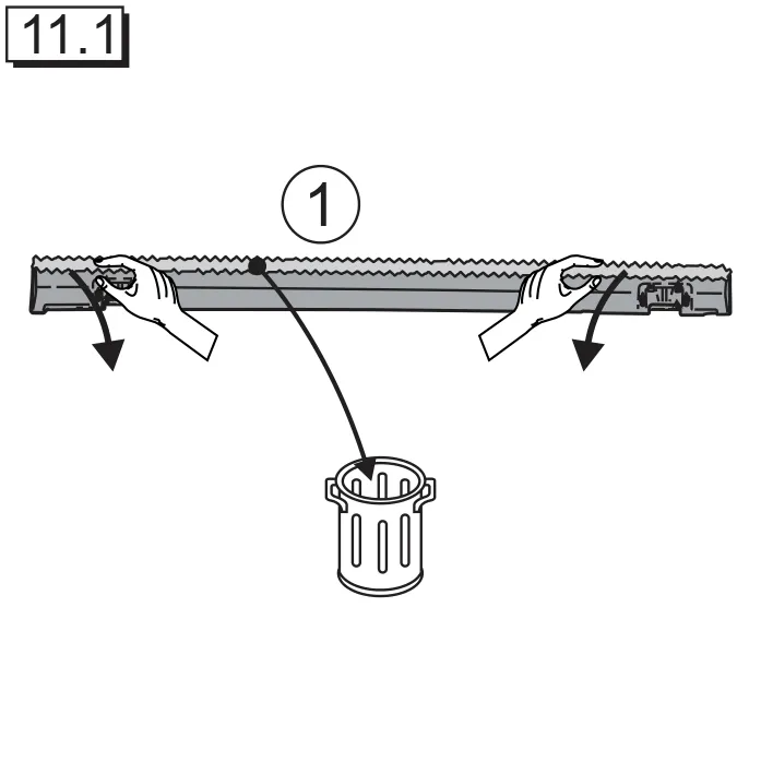
11.1 Remove the masking tape on the inside of the side sill (1).
Figure 11.2
11.2 Sand the side sill (1) in the adhesive area using the abrasive paper (20). Then clean thoroughly using the cleaner (17). Cut the nozzle with a diameter of 5mm. Apply adhesive (18) in an even bead of about 5mm (0.2 inches) wide as shown in the illustration. REMOVE ANY RESIDUAL ADHESIVE DIRECTLY AFTER FITTING!
Figure 12.1
12.1 Position the side sill (1).
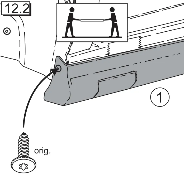
Figure 12.2
12.2 Screw the side sill (1) in the front wheelhouse using the original screw.
Figure 12.3
12.3 Screw the side sill (1) in the rear wheelhouse using the screw (11).
Figure 13.1
13.1 Screw the side sill (1) to the front bracket (3) in the front area using the screw (11).
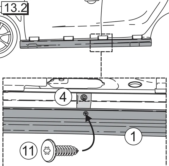
Figure 13.2
13.2 Screw the side sill (1) to the centre bracket (4) in the centre area using the screw (11).
Figure 13.3
13.3 Screw the side sill (1) to the rear bracket (5) in the rear area using the screw (11).
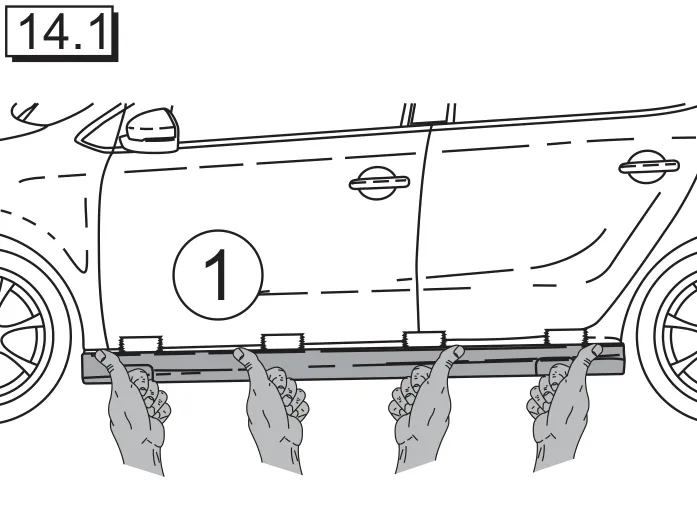
Figure 14.1
14.1 Press the side sill (1) firmly in place along the whole length.
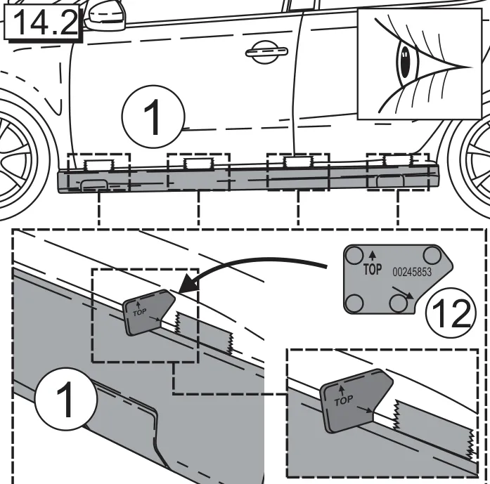
Figure 14.2
14.2 Use the template (12) to check the correct position of the side sill (1).
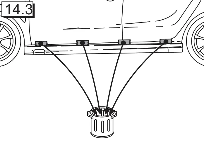
Figure 14.3
14.3 Remove adhesive tape.
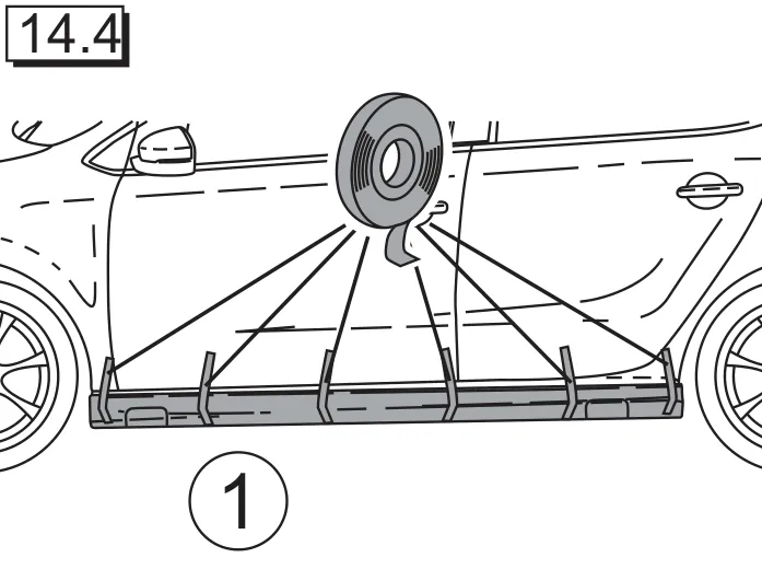
Figure 14.4
14.4 Fix the side sill (1) in place with adhesive tape and press in position. Note: Remove any escaping residue adhesive immediately using cleaner (17) and spatula (19)! The adhesive tape must be left in place for at least 12 hours.
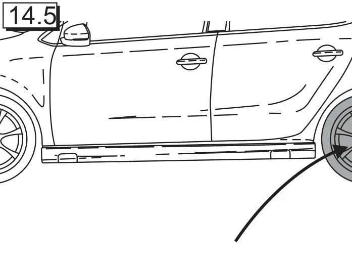
Figure 14.5
14.5 Fit rear tyres.

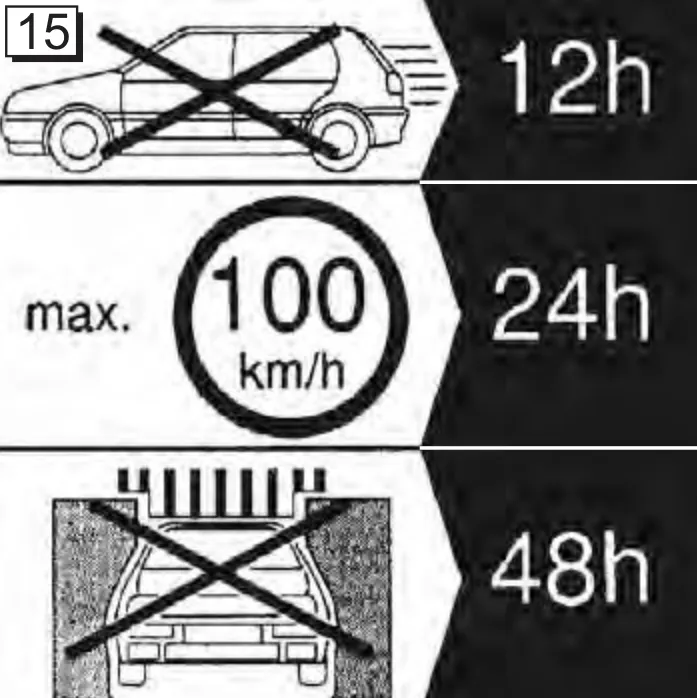
Curing times

15. Curing times
15. Curing times

15. Attention:

  • Do not remove adhesive tape until after approx. 12 hours.
  • No mechanical load may be applied to body part for 24 hours.
  • Do not wash for 48 hours.