
Running gear, axles, steering · Front suspension · Wheel bearing
Removing and installing wheel bearing unit
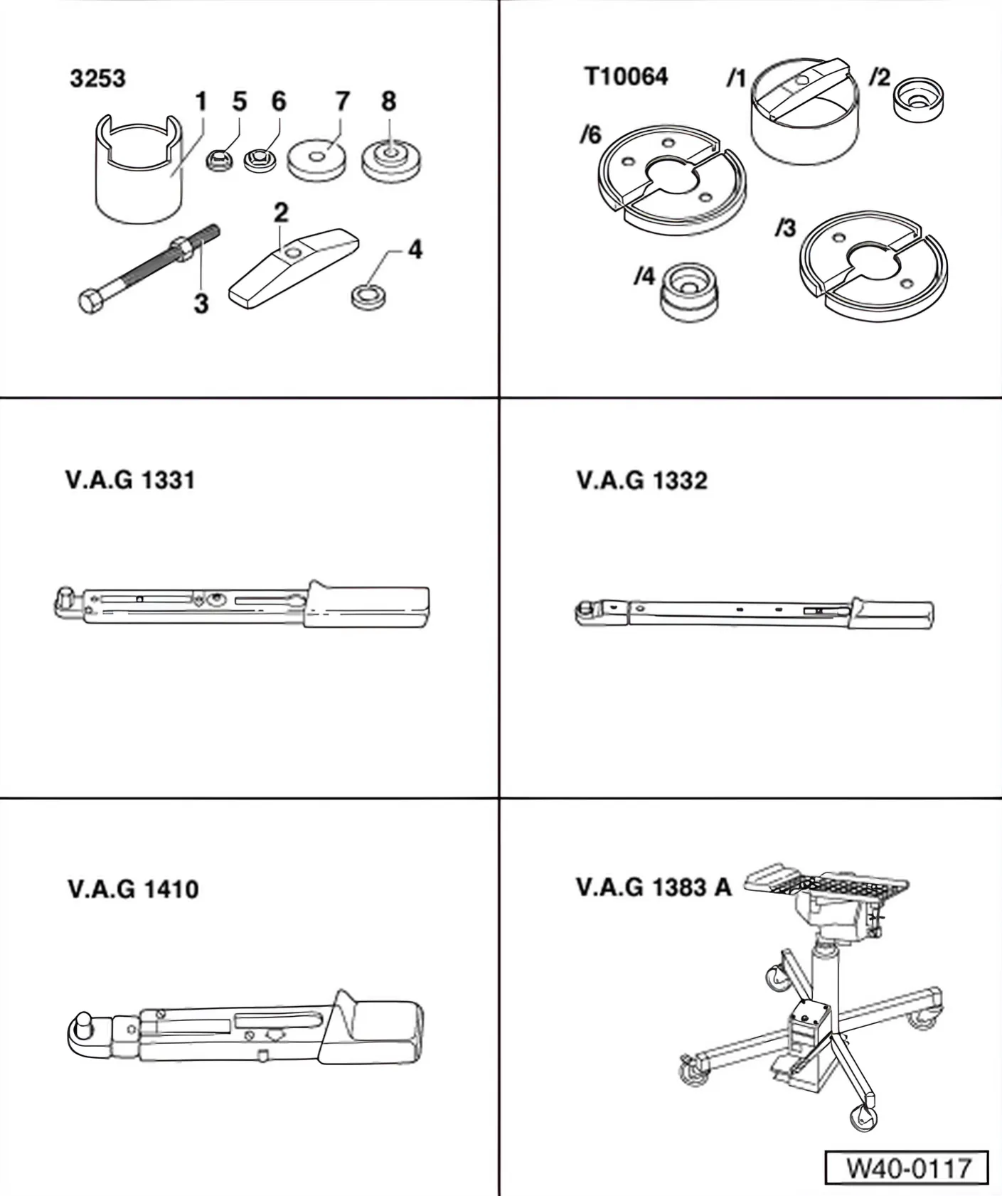
Special tools and workshop equipment required
- Assembly tool - 3253-
- Assembly tool - T10064-
- Torque wrench - V.A.G 1331-
- Torque wrench - V.A.G 1332-
- Torque wrench - V.A.G 1410-
- Engine and gearbox jack - V.A.G 1383 A-
- Universal gearbox mounting - V.A.G 1359/2-

- Open-end spanner (50 mm) - 3254-
- 36 mm socket - T10125-
- Assembly tool - T10205-
- Hydraulic cylinder - VAS 6178-
- Foot pump - VAS 6179-
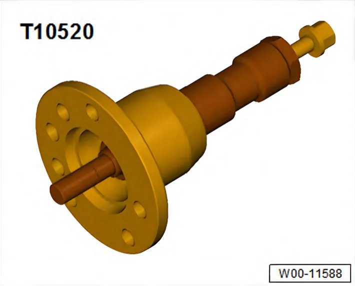
- Ejector - T10520-
Removing
- Lift vehicle far enough to take weight off front axle.
- Undo 12-point drive shaft nut using 36 mm socket - T10125-.
- Remove wheel.
- Unscrew bolt for brake hose bracket.
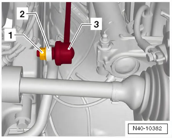
- Remove hexagon nut -1- from coupling rod (left and right sides).
- Pull coupling rod -3- out of anti-roll bar -2- on left and right sides.
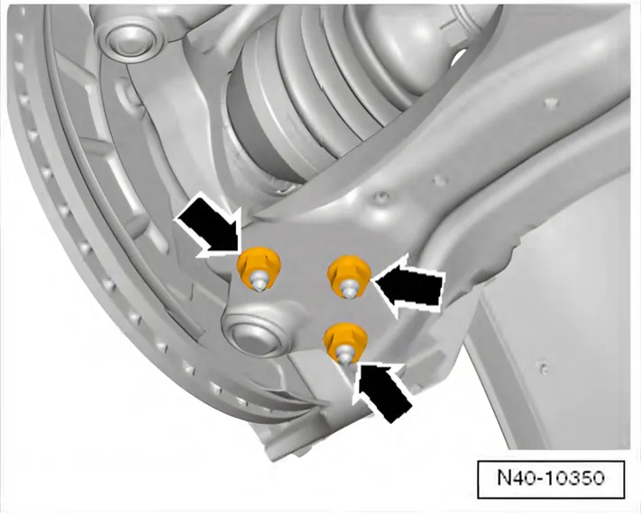
- Remove nuts -arrows-
- Pull swivel joint out of suspension link.

- Pivot suspension strut outwards and hold in place with a wooden block or similar -1-; at the same time pull drive shaft out of wheel bearing.
If the drive shaft cannot be pulled out of the wheel bearing by hand, use press tool - T10520- or press tool - 3283 A-.
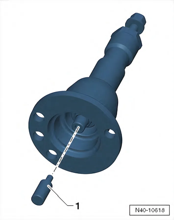
Before using pressure tool - T10520-, make sure that thrust piece -1- is inserted.
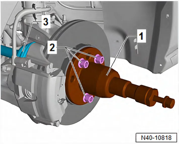
Using ejector - T10520- :
- To press out drive shaft -3-, secure ejector - T10520- -1- to wheel hub using 3 wheel bolts -2-.
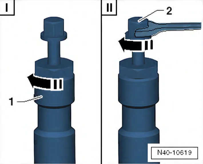
- It is essential to follow specified sequence.
I - Tighten knurled nut -1- hand-tight.
II - Using spanner, turn only bolt -2-, not the press tool itself. Pull out drive shaft using press tool - T10520-.
- Secure drive shaft to body with wire.
The drive shaft must not hang down under its own weight.
Otherwise the inner joint will be bent too far and will be damaged.
- Remove brake carrier together with brake caliper, or just brake caliper, and secure it to body with wire ⇒ Brake system; Rep. gr. 46; Front brake; Removing and installing brake caliper.
- Remove bolt for brake disc and remove brake disc.
- Remove splash plate.
- Remove ABS speed sensor ⇒ Brake system; Rep. gr. 45; Sensors; Removing and installing speed sensor on front axle
- G45- / -G47-.
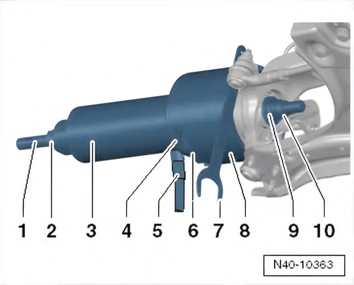
Pulling out wheel hub with wheel bearing
- Insert open-end spanner, 50 mm - 3254- between tube - 3253/1- and mounting surface -arrow- on steering arm.
- Hold appliance firmly and pull out wheel hub with wheel bearing.
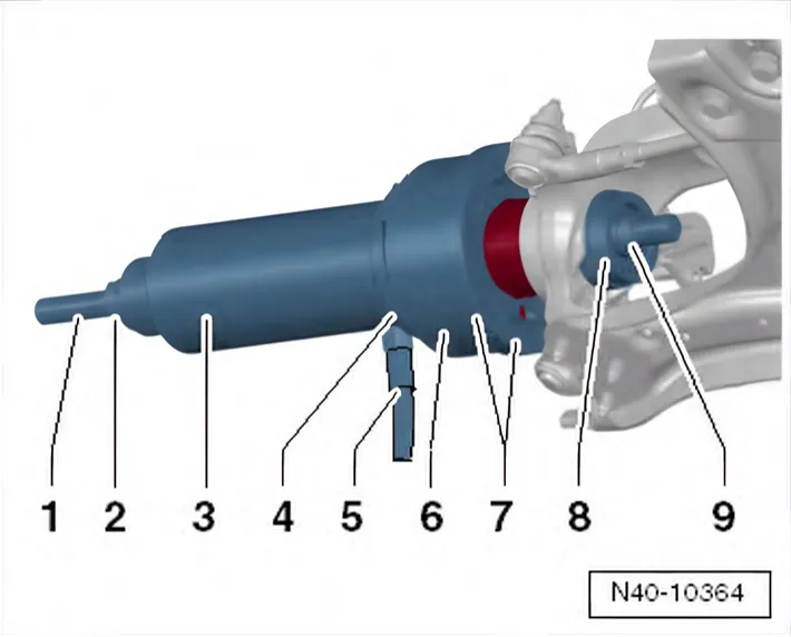
- 1 Spindle - T10205/8-1-
- 2 Nut - T10205/8-2-
- 3 Hydraulic press - VAS 6178- and thrust piece - T10205/13-
- 4 Pressure plate - T10205/4-
- 5 Foot pump - VAS 6179-
- 6 Bracket - 3253/2-
- 7 Open-end spanner AF 50 - 3254-
- 8 Tube - 3253/1-
- 9 Thrust piece - T10205/3-, with large diameter facing to‐
wards wheel bearing
10 - Nut - T10205/8-2-
Installing
- Remove remains of circlip from the bore and groove of wheel bearing housing.
- Clean bore of wheel bearing housing.
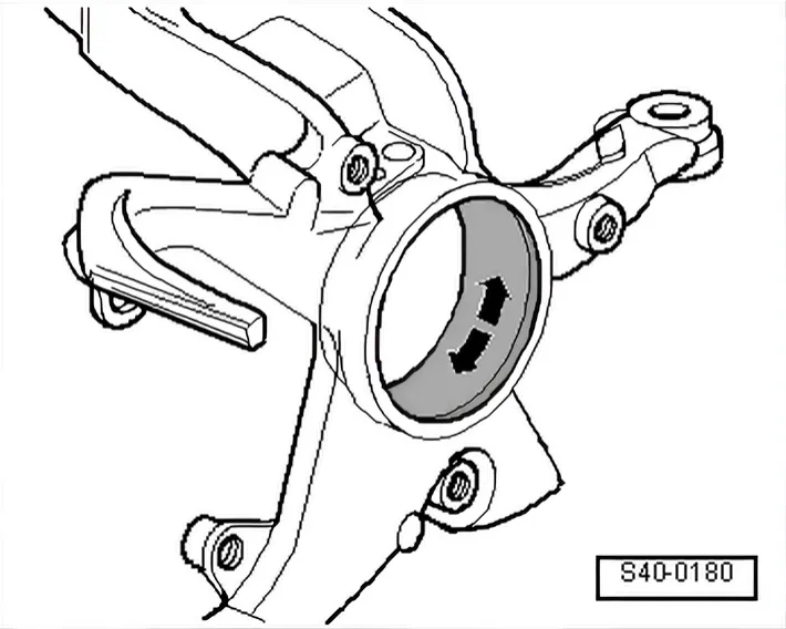
- Fully coat bore with Moly paste - G 052 723 A2-.
Use grease sachet from repair kit.
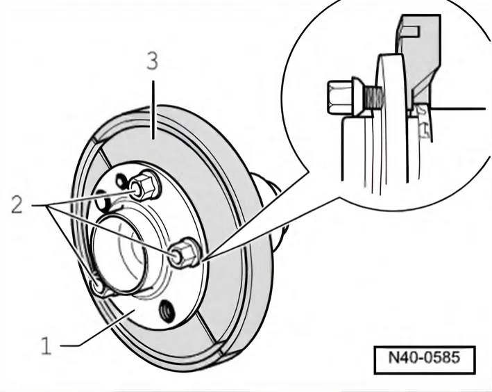
- Screw wheel bolts -2- into wheel hub.
- Fit gripping pieces - T10064/6A- onto the wheel bolts.
- 1 Wheel hub with wheel bearing
- 2 Wheel bolts
- 3 -T10064/6A-
Wheel bolts -2- must not protrude from backs of gripping pieces
- T10064/6A-.
Installing wheel hub with wheel bearing
Make sure wheel hub/wheel bearing unit is kept straight when installing.
- Pull in wheel hub together with wheel bearings until circlip engages audibly.
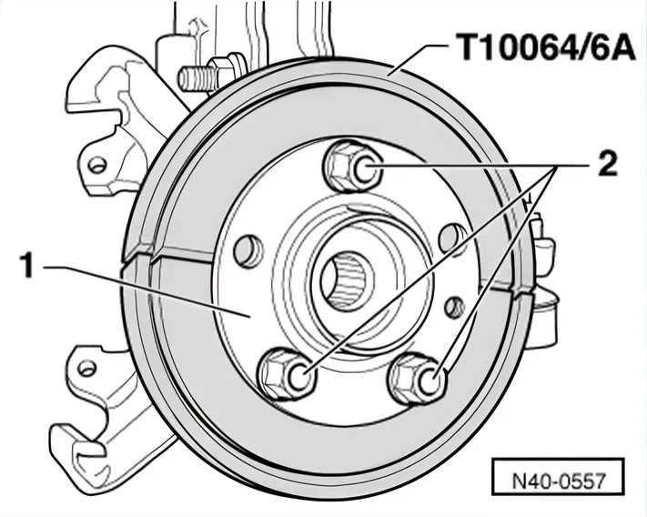
- 1 Spindle - T10205/8-1-
- 2 Nut - T10205/8-2-
- 3 Hydraulic press - VAS 6178- and thrust piece - T10205/13-
- 4 Pressure plate - T10205/4-
- 5 Foot pump - VAS 6179-
- 6 Tube - T10064/1-
- 7 Gripping pieces - T10064/6A-
- 8 Thrust piece - T10064/4-, with large diameter facing to‐
wards wheel bearing housing
- 9 Nut - T10205/8-2-
- Unscrew wheel bolts -2- from wheel hub with wheel bearings -1-.
- Remove gripping pieces - T10064/6A-.
- Insert drive shaft into wheel hub with wheel bearings.
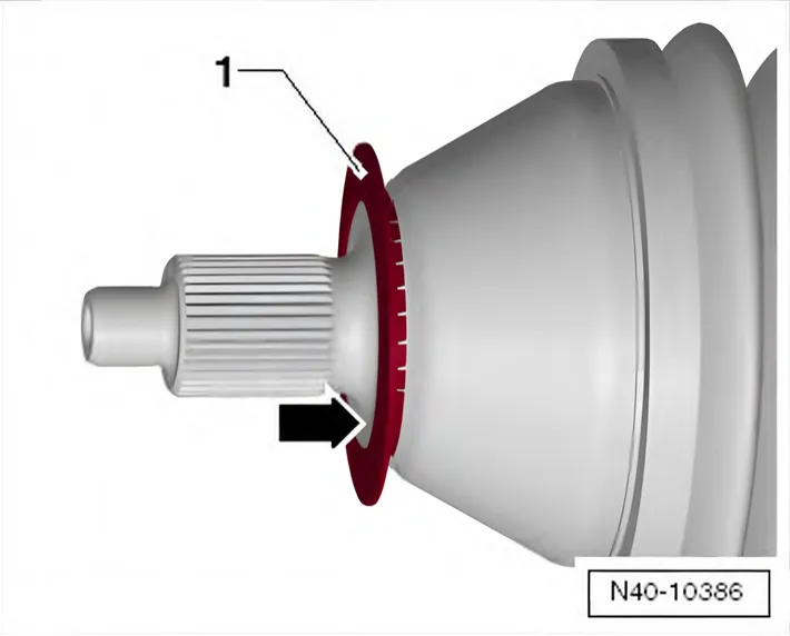
Make sure that deflector ring -1- is clipped completely onto outer joint.
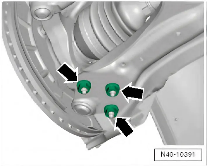
- Bolt swivel joint to suspension link with new nuts -arrows-.
Use new nuts!
6C 2014–2017
Ensure that boot is not damaged or twisted.
- Install ABS speed sensor.
- Install splash plate, brake disc and brake carrier with brake caliper, or the brake caliper alone ⇒ Brake system; Rep. gr. 46; Front brake; Removing and installing splash plate.
- Fit bracket for brake hose to wheel bearing housing.
- Attach coupling rod to anti-roll bar.
- Install wheel and tighten bolts or nuts ⇒ 1.5 Specified torques for wheel bolts.
- Tighten 12-point drive shaft nut using 36 mm socket - T10125-.
Specified torques
| Component | Specified torque |
|---|---|
| 6R 2009–2014 Swivel joint to suspension link ♦ Use new bolts | 100 Nm |
| 6C 2014–2017 Swivel joint to suspension link ♦ Use new bolts | 40 Nm +45° |
| Coupling rod to anti-roll bar | 40 Nm |
| 12-point nut on drive shaft ♦ Use new bolts | 50 Nm +45° |
The two manuals give different torques for the same swivel joint nuts (N10332002): 100 Nm in the Polo 6R manual, 40 Nm +45° in the Polo 6C manual. Other cars with the same swivel joints differ too: the Audi A1 8X manual gives 100 Nm, the Škoda Fabia II manual 40 Nm +45°.
6C 2014–2017