
Running gear, axles, steering · Front suspension · Suspension strut, upper suspension link
Removing and installing suspension strut
⇒ 3.2.1 Removing and installing suspension strut, basic version of running gear
⇒ 3.2.2 Removing and installing suspension strut, Sport Select running gear
3.2.1 Removing and installing suspension strut, basic version of running gear
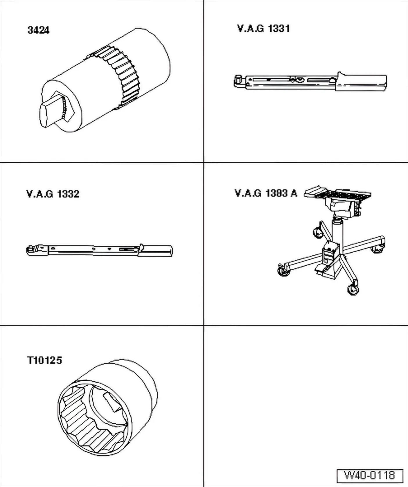
Special tools and workshop equipment required
- Spreader - 3424-
- Torque wrench - V.A.G 1331-
- Torque wrench - V.A.G 1332-
- Engine and gearbox jack - V.A.G 1383 A-
- 36 mm socket - T10125-
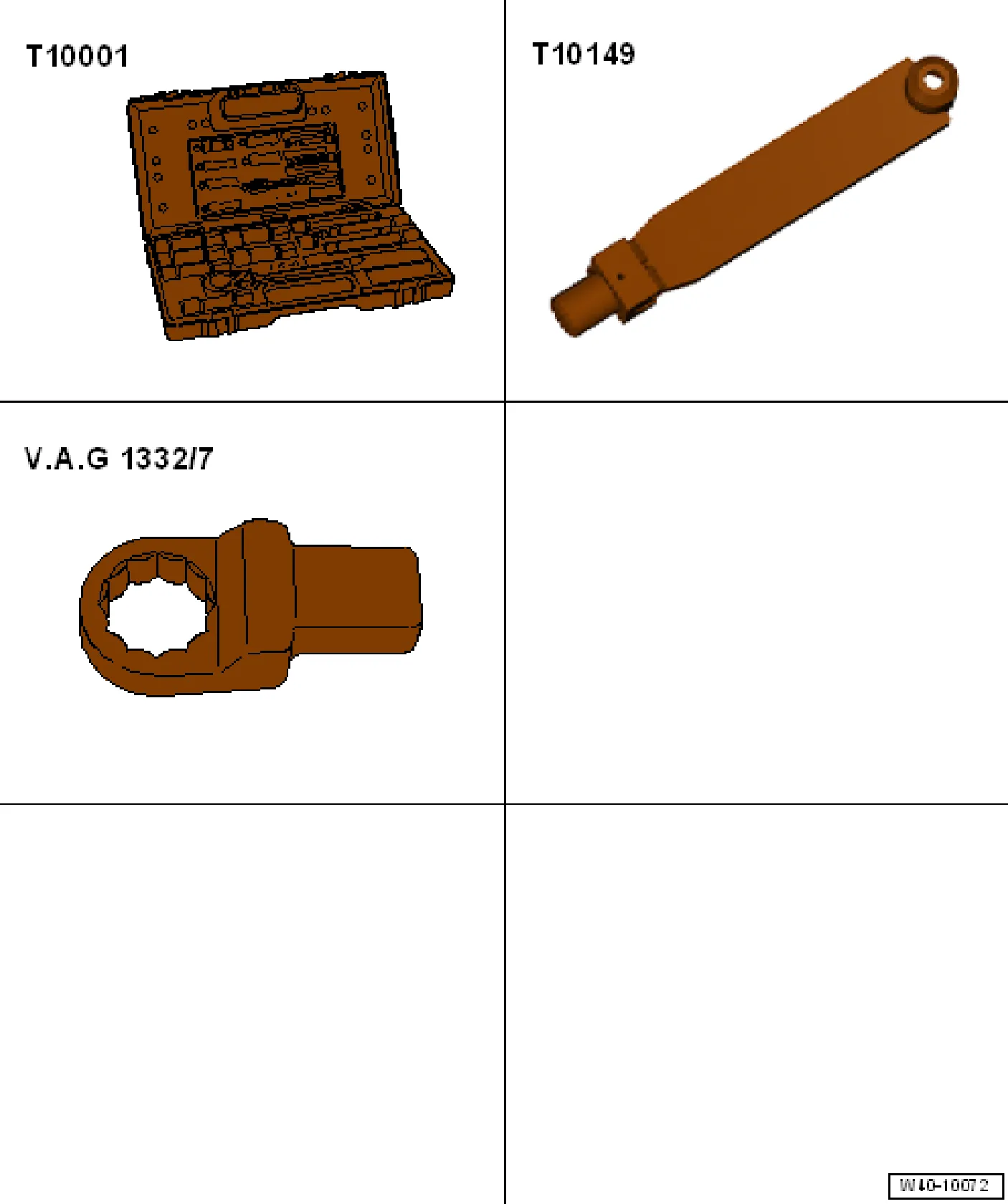
- Shock absorber tool set - T10001-
- Support - T10149-
- Ring spanner insert - V.A.G 1332/7-

- Ejector - T10520-
Removing
- Lift vehicle far enough to take weight off front axle.
- Undo 12-point drive shaft nut using 36 mm socket - T10125-.
- Remove wheel.
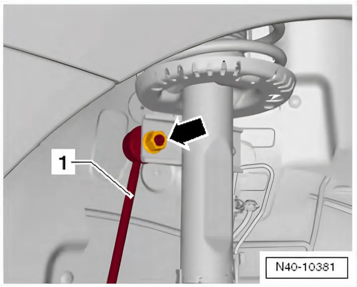
- Unscrew nut -arrow- and pull coupling rod -1- out from suspension strut.
- Detach wire for speed sensor from suspension strut.

- Remove clip for brake line -arrow- and unhook brake line at spring strut.
- Pull connector off ABS speed sensor.
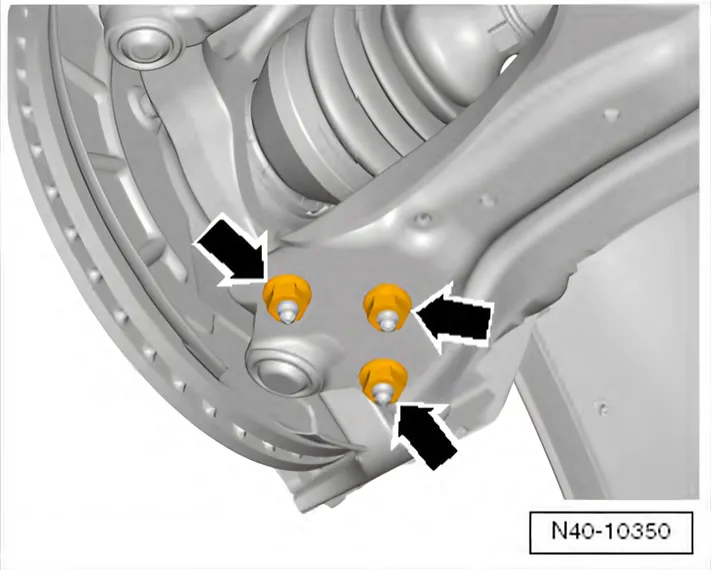
- Remove nuts -arrows-
- Pull swivel joint out of suspension link.
- Pull outer joint of drive shaft out of wheel hub.
- Secure drive shaft to body with wire.
If the drive shaft cannot be pulled out of the wheel bearing by hand, use press tool - T10520- or press tool - 3283 A-.
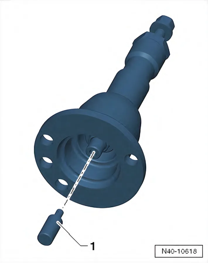
Before using pressure tool - T10520-, make sure that thrust piece -1- is inserted.
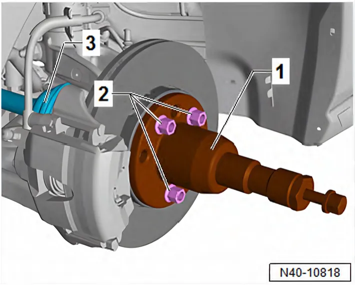
Using ejector - T10520- :
- To press out drive shaft -3-, secure ejector - T10520- -1- to wheel hub using 3 wheel bolts -2-.
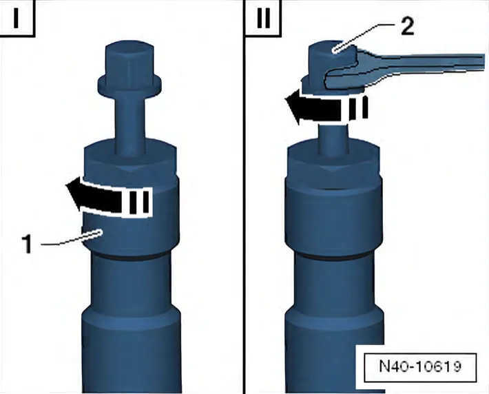
- It is essential to follow specified sequence.
I - Tighten knurled nut -1- hand-tight.
II - Using spanner, turn only bolt -2-, not the press tool itself. Pull out drive shaft using press tool - T10520-.
- Bolt swivel joint to suspension link again.
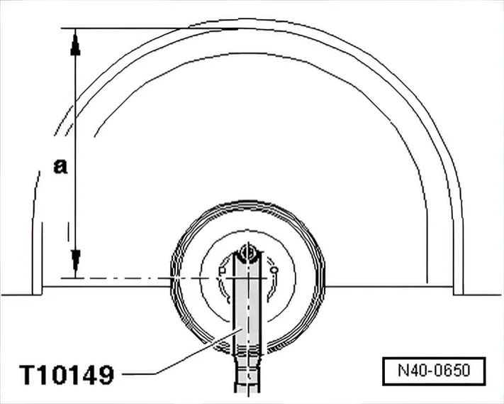
- Use wheel bolt to attach engine and gearbox jack - V.A.G 1383 A- with support - T10149- to wheel hub.

- Separate threaded connection between wheel bearing housing and suspension strut -arrow-.

- Insert spreader - 3424- in slot in wheel bearing housing.
- Turn ratchet handle through 90° and pull off from spreader - 3424-.
- Press brake disc towards suspension strut by hand.
Otherwise the shock absorber tube can cant in the bore of the wheel bearing housing.
- Pull wheel bearing housing downwards off shock absorber tube and lower with engine and gearbox jack - V.A.G 1383 A- until shock absorber tube is free.
- 6R 2009–2014 Tie wheel bearing housing to subframe with wire.
- 6C 2014–2017 Use wire to secure wheel bearing housing to engine/gearbox mounting.
- Pull engine and gearbox jack - V.A.G 1383 A- out from under support - T10149-.
- Remove plenum chamber cover ⇒ General body repairs, exterior; Rep. gr. 50; Bulkhead; Removing and installing plenum chamber cover.
- If fitted, detach cap from shock absorber mounting.
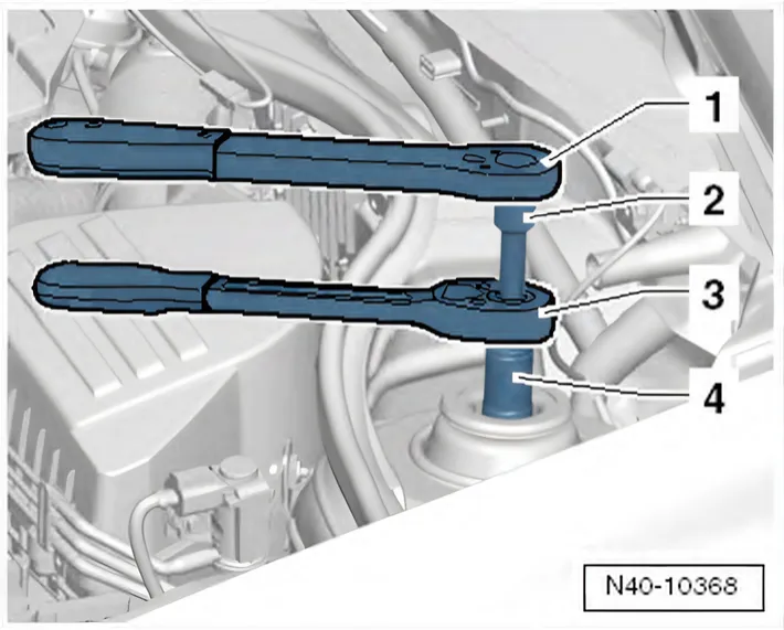
- Unbolt upper shock absorber mounting and remove spring strut downwards.
- 1 Ratchet, commercially available
- 2 -T10001/8-
- 3 -T10001/11-
- 4 -T10001/5-
Installing
- Use wheel bolt to attach engine and gearbox jack - V.A.G 1383 A- with support - T10149- to wheel hub.
- Place suspension strut on wheel bearing housing and fix in place with the multi-point socket head bolt and a new nut.
The tip of the multi-point socket head bolt must point in the direction of travel.
- Remove wire on wheel bearing housing.
- Remove spreader - 3424-.
- Raise wheel bearing housing using engine and gearbox jack until suspension strut lies against inner suspension turret.

- Position stop on suspension strut turret and tighten nuts for upper shock absorber mounting to tightening torque.
- 1 Ratchet, commercially available
- 2 -T10001/8-
- 3 Ring spanner insert - V.A.G 1332/7-
- 4 -T10001/5-
- 5 Torque wrench - V.A.G 1332-
- Remove support - T10149- from wheel hub.
- Remove engine and gearbox jack - V.A.G 1383 A- from under vehicle.
- If removed beforehand, attach cap to shock absorber mounting.
- Install plenum chamber cover ⇒ General body repairs, exterior; Rep. gr. 50; Bulkhead; Removing and installing plenum chamber cover.
- Tighten threaded connection between wheel bearing housing and suspension strut -arrow-
- Remove nuts -arrows-
- Pull swivel joint out of suspension link.
- Fit drive shaft into wheel bearing.
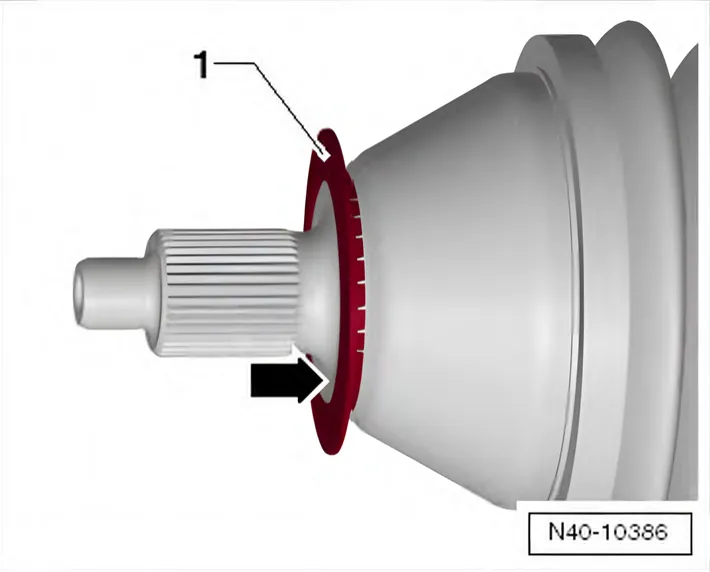
Make sure that deflector ring -1- is clipped completely onto outer joint.
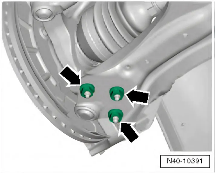
- Bolt swivel joint to suspension link with new nuts -arrows-.
Use new nuts!
6C 2014–2017
Ensure that boot is not damaged or twisted.
Continue installation in reverse order of removal.
- Install wheel and tighten bolts or nuts ⇒ 1.5 Specified torques for wheel bolts.
- Tighten 12-point drive shaft nut using 36 mm socket - T10125-.
Specified torques
| Component | Specified torque |
|---|---|
| Coil spring strut to body ♦ Use new bolts | 60 Nm |
| Suspension strut to wheel bearing housing ♦ Use new bolts and nuts. | 60 Nm +90° |
| 6R 2009–2014 Swivel joint to suspension link ♦ Use new bolts | 100 Nm |
| 6C 2014–2017 Swivel joint to suspension link ♦ Use new bolts | 40 Nm +45° |
| Coupling rod to suspension strut ♦ Use new bolts | 40 Nm |
| 12-point nut on drive shaft ♦ Use new bolts | 50 Nm +45° |
The two manuals give different torques for the same swivel joint nuts (N10332002): 100 Nm in the Polo 6R manual, 40 Nm +45° in the Polo 6C manual. Other cars with the same swivel joints differ too: the Audi A1 8X manual gives 100 Nm, the Škoda Fabia II manual 40 Nm +45°.
6C 2014–2017
- ⇒ 3.1 Assembly overview - suspension strut, upper suspension link
- ⇒ 2.1 Assembly overview - subframe
- ⇒ 5.1 Assembly overview - wheel bearing
- ⇒ 6.2 Assembly overview - drive shaft
3.2.2 Removing and installing suspension strut, “Sport Select” running gear
Only what differs from the procedure above; everything else is as above.
Removing
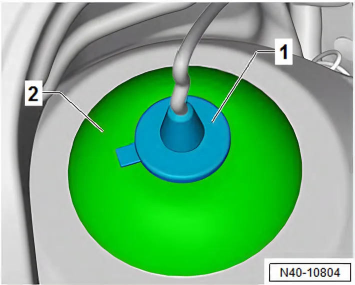
- Remove cap -1- from cover -2-.
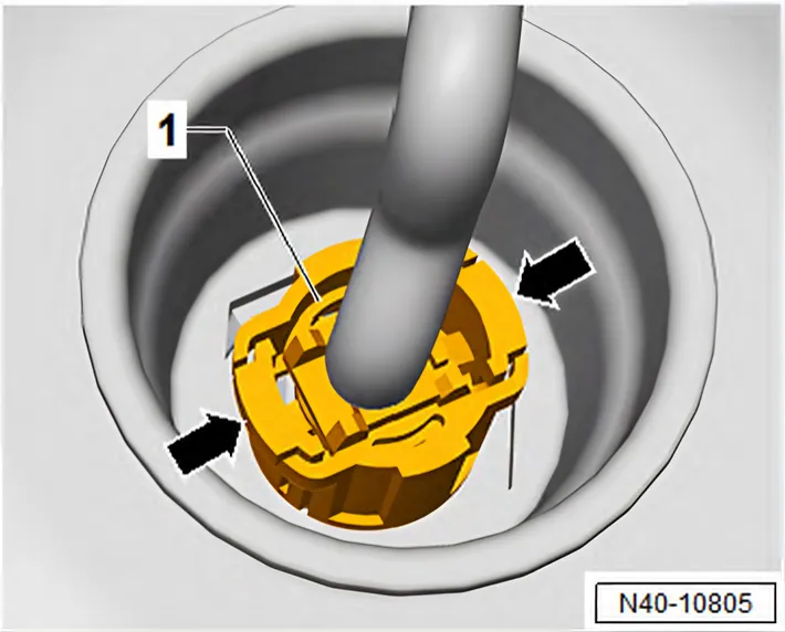
- Press lugs -arrows- inwards, and pull connector -1- off shock absorber.
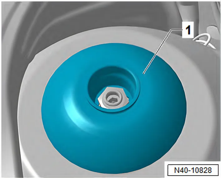
- Lever off cover -1-.
Installing
- Fit cover -1-.
- Fit connector -1- onto shock absorber. Lugs -arrows- must audibly engage.
- Fit cap -1- onto cover -2-.
Use new nuts!