
Running gear, axles, steering · Front suspension · Drive shaft
Dismantling and assembling drive shaft
⇒ 6.6.1 Dismantling and assembling drive shaft, joint body TS1800
⇒ 6.6.2 Dismantling and assembling drive shaft, constant velocity joints VL90 and VL100
⇒ 6.6.3 Dismantling and assembling drive shaft, constant velocity joint VL107, threaded connection
⇒ 6.6.4 Dismantling and assembling drive shaft, constant velocity joint VL107, plug-in connection
6C 2014–2017 6.6.1 Dismantling and assembling drive shaft, joint body TS1800
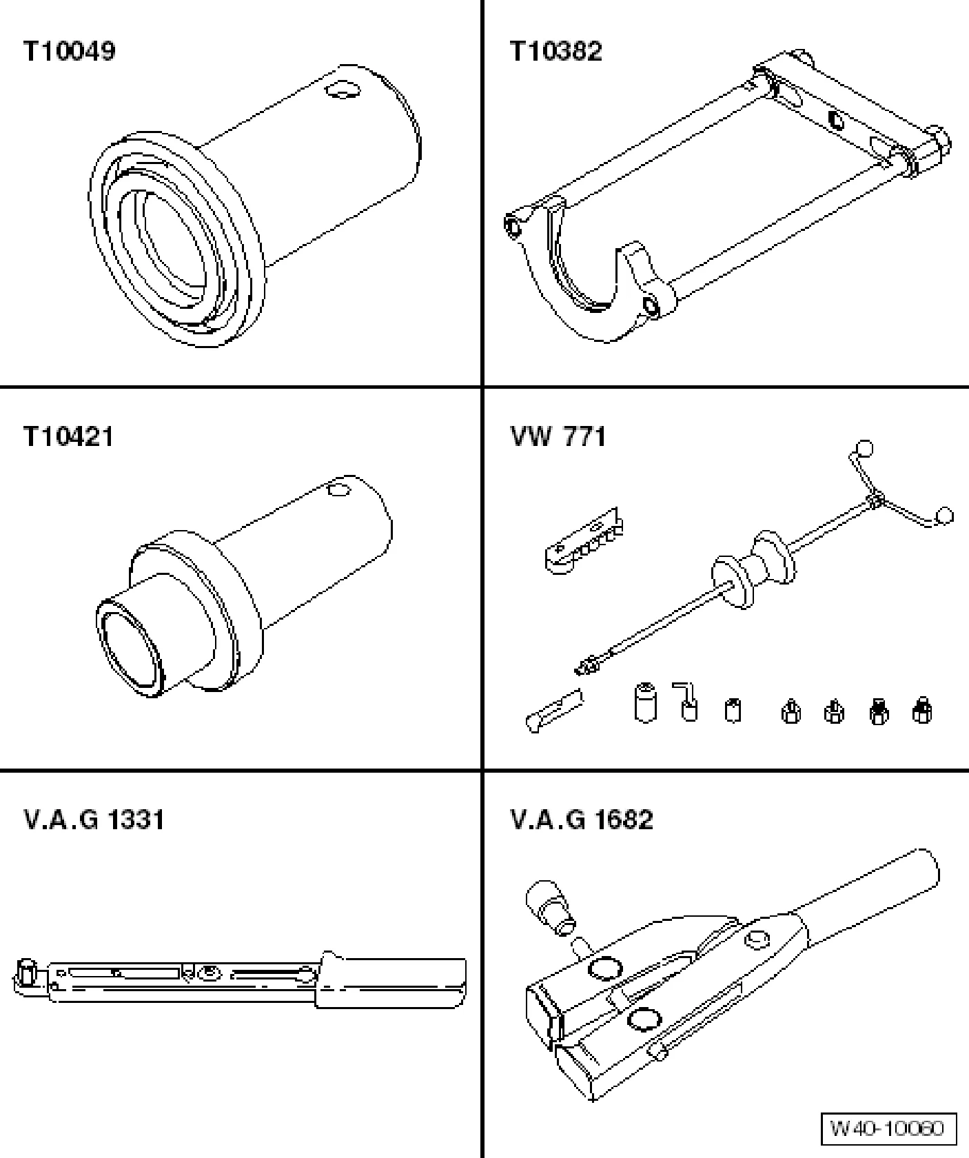
Special tools and workshop equipment required
- Thrust piece - T10049-
- Puller - T10382-
- Thrust piece - T10421-
- Multi-purpose tool - VW 771-
- Torque wrench - V.A.G 1331-
- Clamp tensioner - V.A.G 1682-
- Three-arm puller - Kukko 45-1-
Removing outer constant velocity joint
- Clamp drive shaft in vice using jaw protectors.
- Open O-type clip.
- Fold back boot.
- Set puller - T10382- up so that smooth side of puller plate - T10382/1- points to spindles - T10382/2-.
- Assemble puller - T10382- complete with multi-purpose tool - VW 771-.
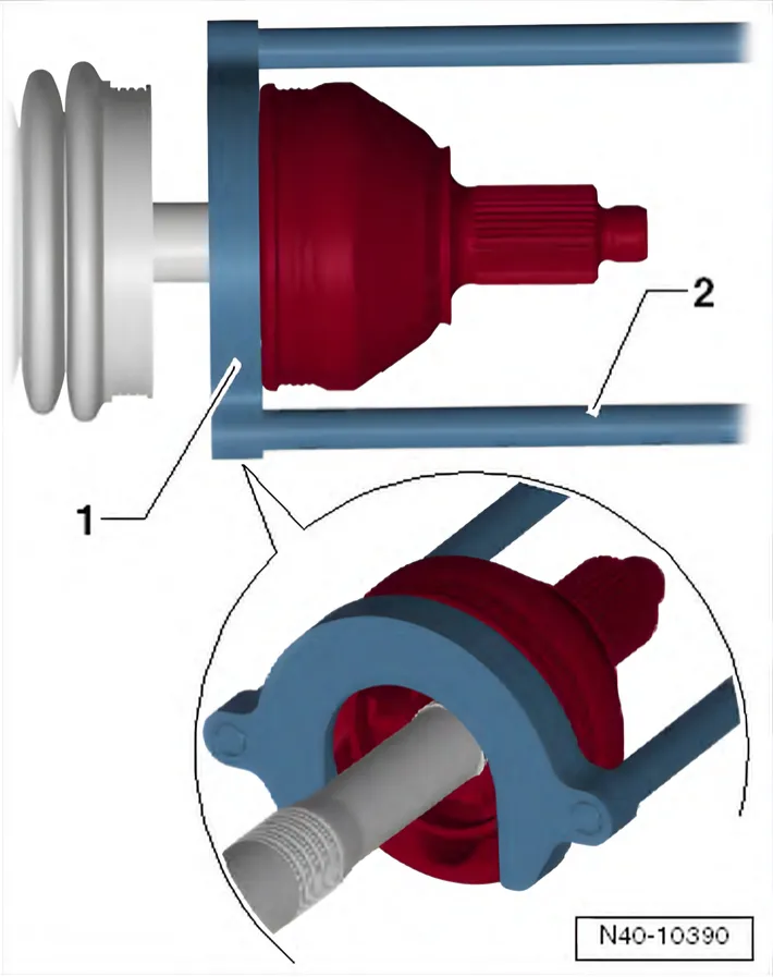
- Pull constant velocity joint from drive shaft with puller - T10382- and multi-purpose tool - VW 771-.
- 1 Puller plate - T10382/1-
- 2 Spindles - T10382/2-
Driving on outer constant velocity joint
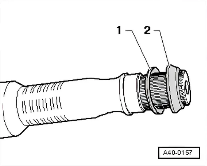
Installation position of dished spring and spacer ring on outer joint
- 1 Dished spring
- 2 Spacer ring
- Install new retaining ring.
- If necessary, push new joint boot onto drive shaft.
- Drive constant velocity joint onto shaft using plastic hammer until retaining ring engages.
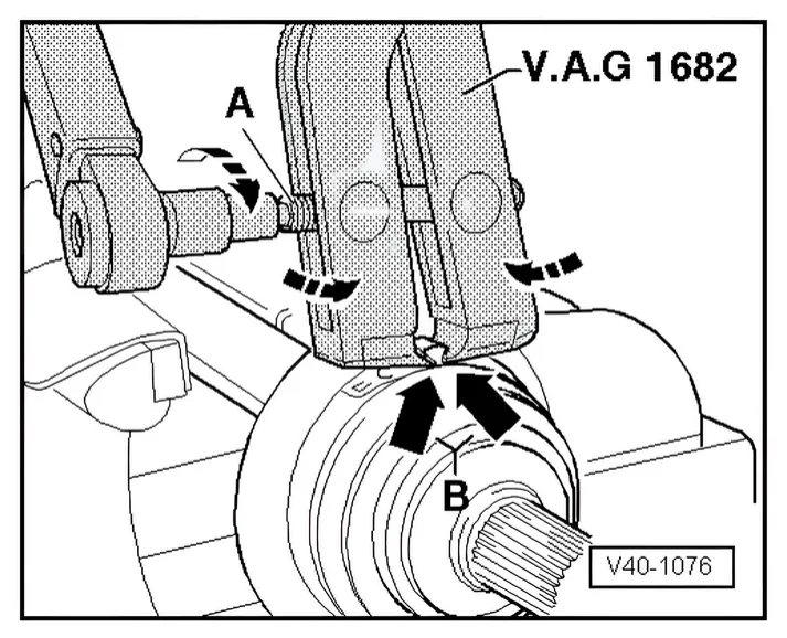
Tightening new clamp on constant velocity joint
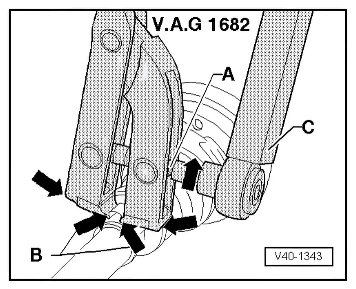
- Position clamp tensioner - V.A.G 1682- as shown in diagram. Ensure jaws of tensioner lie in corners -arrows B- of clamp.
- Tighten clamp by turning spindle with a torque wrench (do not cant pliers).
Tightening new clamp on small diameter
- Position clamp tensioner - V.A.G 1682- as shown in diagram. Ensure jaws of tensioner lie in corners -arrows B- of clamp.
- Tighten clamp by turning spindle with a torque wrench (do not cant pliers).
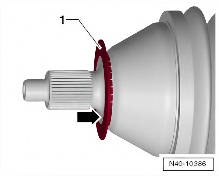
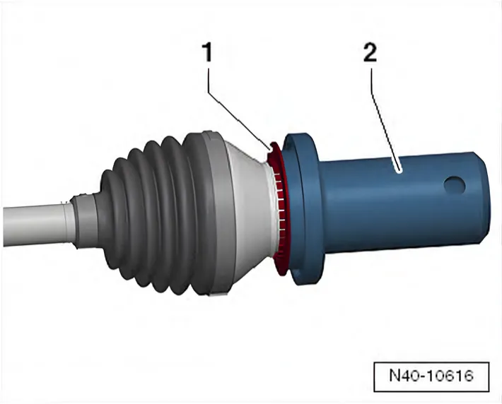
Make sure that deflector ring -1- is clipped completely onto outer joint.
Dismantling
- Open both clip on inner joint and push back boot.
- Pull joint body off drive shaft.
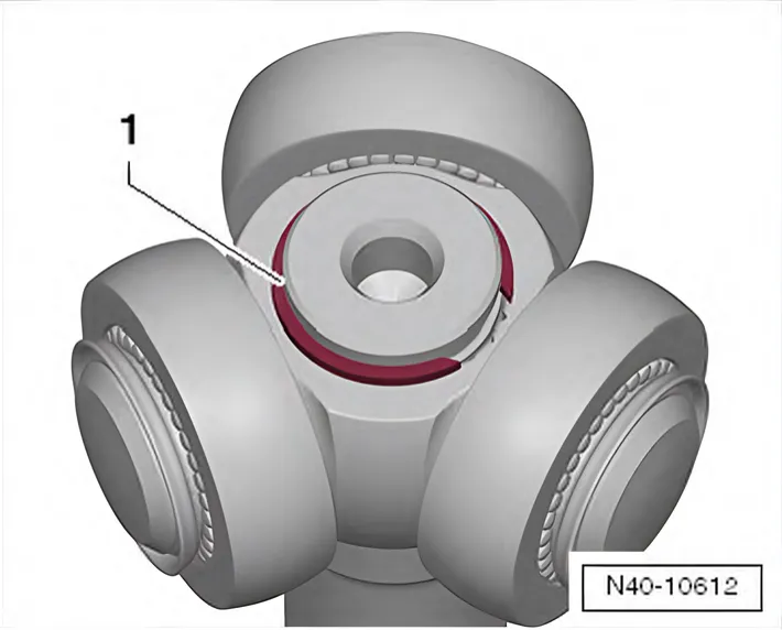
- Remove retaining ring -1-.
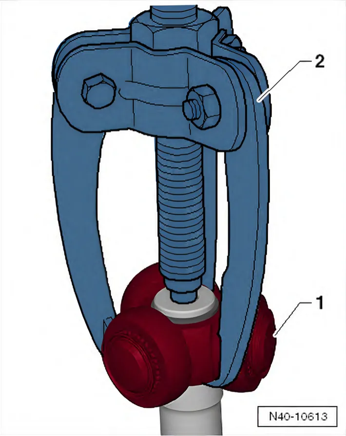
- Pull triple roller star -1- off drive shaft using a three arm puller, e.g. -Kukko 45-1- -2-.
- Pull boot off shaft.
- Clean shaft, joint body and groove for seal.
Installing
- Push small hose clip for boot onto shaft.
- Push joint boot onto shaft.
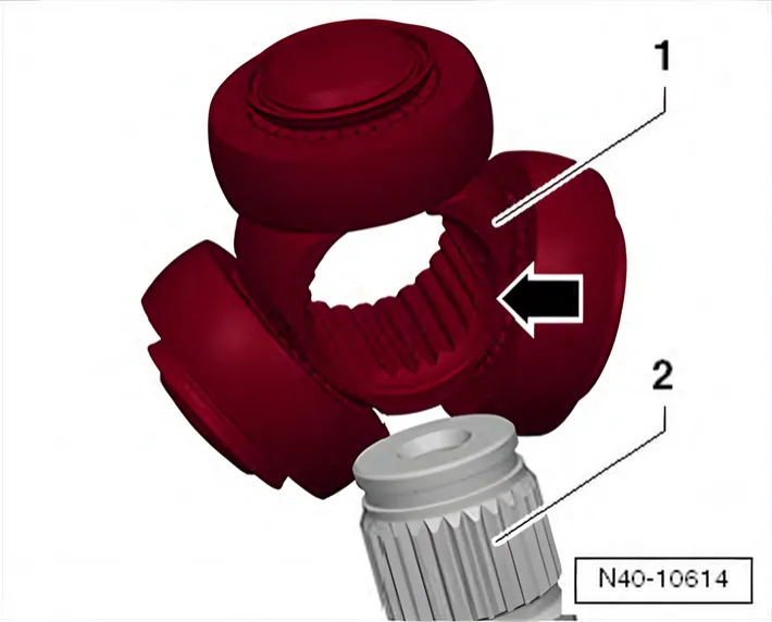
- Fit triple roller star -1- onto drive shaft -2-.
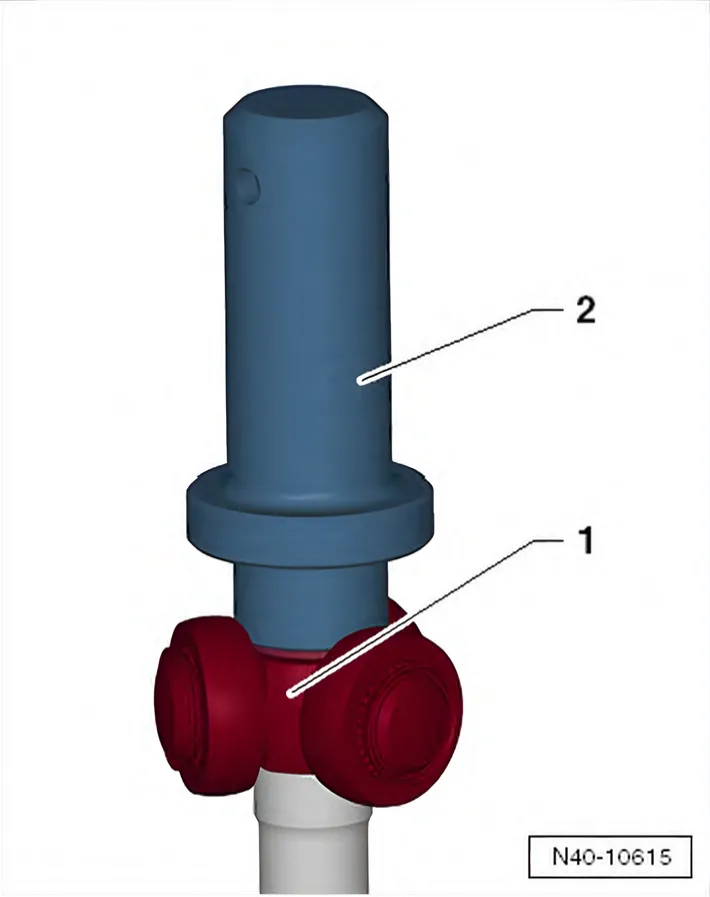
- Drive triple roller star -1- onto drive shaft using thrust piece - T10421- -2-.
- Insert circlip -1-, ensuring that it is seated correctly.
- Press half the drive shaft grease from the repair kit into the triple roller joint.
- Slide joint body over rollers and hold.
- Press the other half of the drive shaft grease from the repair kit into the back of the triple roller joint.
- Install joint boot.
- Tighten clamp on small diameter ⇒ 6.6.1 Dismantling and assembling drive shaft, joint body TS1800.
- Tighten new clamp on constant velocity joint ⇒ 6.6.1 Dismantling and assembling drive shaft, joint body TS1800.
6.6.2 Dismantling and assembling drive shaft, constant velocity joints VL90 and VL100
Only what differs from the procedure above; everything else is as above.
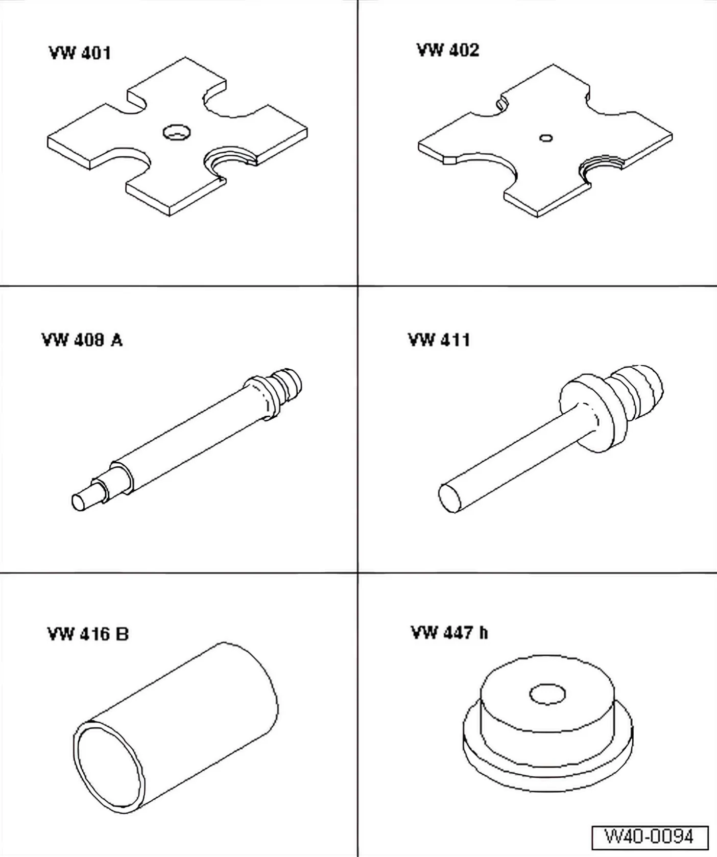
Special tools and workshop equipment required
- Thrust plate - VW 401-
- Thrust plate - VW 402-
- Press tool - VW 408 A-
- Press tool - VW 411-
- Tube - VW 416 B-
- Thrust plate - VW 447 H-
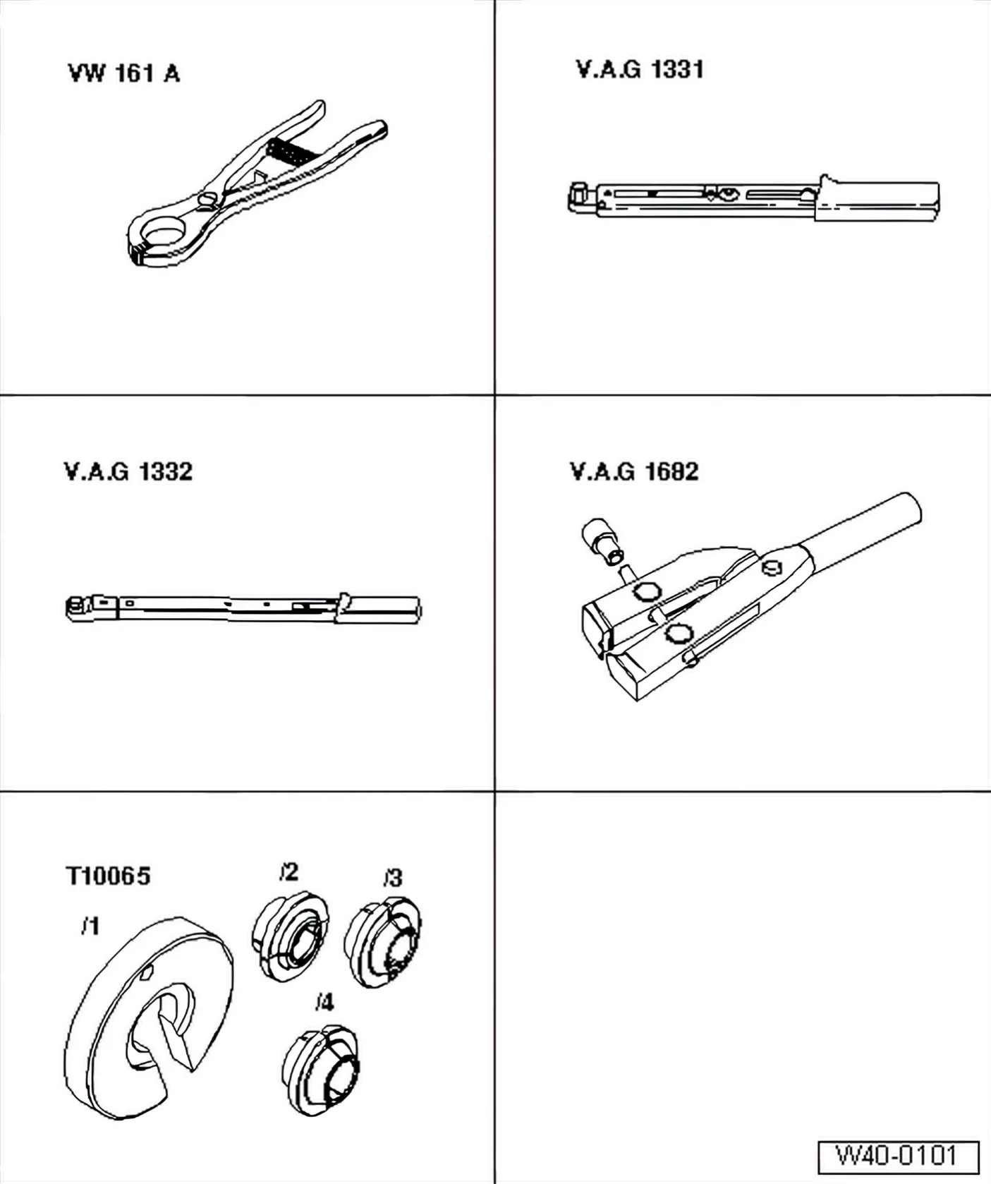
- Snap ring pliers - VW 161 A-
- Torque wrench - V.A.G 1332-
- Assembly tool - T10065-
- 2 Thrust washer
- Knock onto shaft with plastic hammer until retaining ring engages.
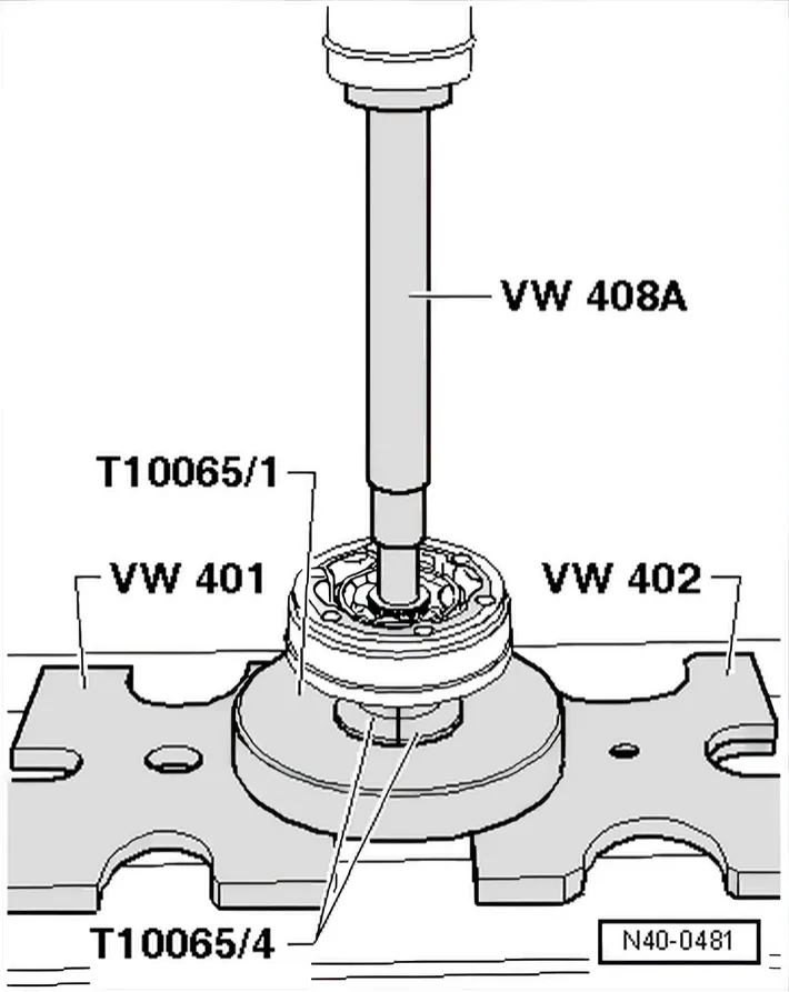
Pressing off inner constant velocity joint
First drive bellows off with drift.
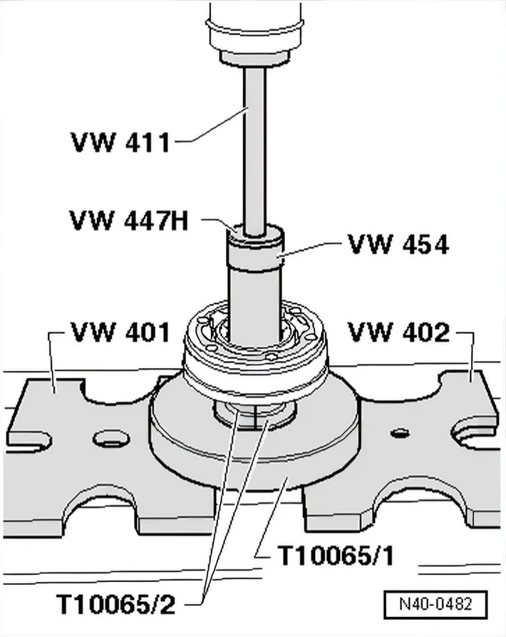
Pressing on inner constant velocity joint
- Press joint on to stop.
- Install retaining ring.
Chamfer on internal circumference of ball hub (splines) must face contact shoulder on drive shaft.
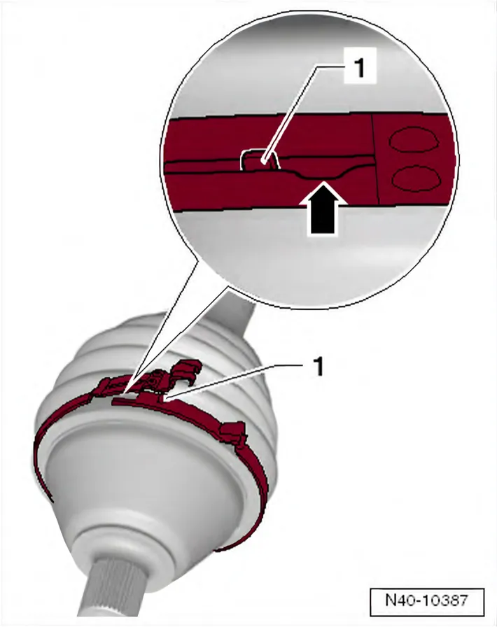
Tensioning clamp on outer joint - variant 1
- Insert lug -1- of clamp into guide -arrow-.
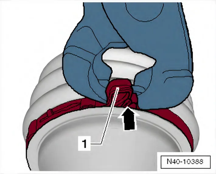
- Compress clamp with pliers, e.g. locking pliers for Phaeton steering rack - VAS 6199- until upper part -1- locks with guide -arrow-.
Tensioning clamp on outer joint - variant 2
Tightening clip on small diameter of inner/outer joint
6.6.3 Dismantling and assembling drive shaft, constant velocity joint VL107, threaded connection
Only what differs from the procedure above; everything else is as above.
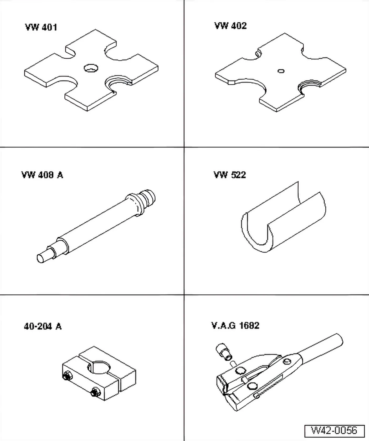
Special tools and workshop equipment required
- Support sleeve - VW 522-
- Joint tensioner - 40 - 204 A-
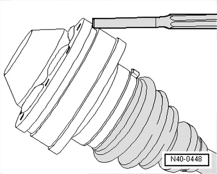
Driving off cover for inner joint
- Remove retaining ring.
- Remove both clips and slide boot towards outer joint.
- Drive off boot with drift.
Installing
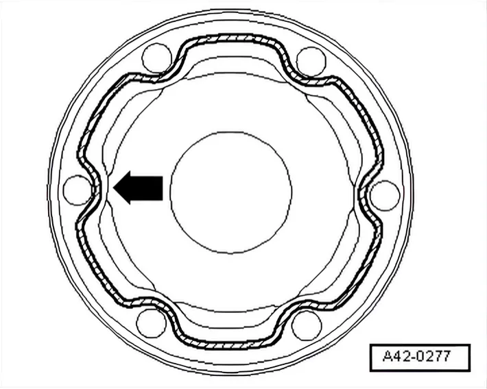
- Coat sealing surface of cover with -D 454 300 A2-.
- Apply an unbroken bead of sealant of 2…3 mm in diameter onto clean surface of cover in area of inner holes -arrow-.
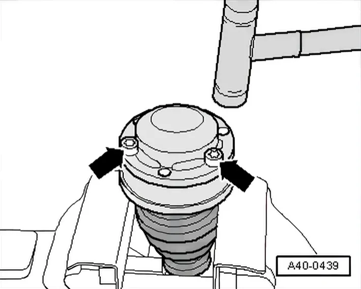
- Using bolts -arrows-, align new cover in relation to bolt holes.
The alignment must be very accurate, because no further alignment is possible once the part has been hammered on.
- Drive on cover with a plastic hammer.
- Wipe off surplus sealant.
- Compress clamp with pliers, e.g. locking pliers for Phaeton steering rack - VAS 6199- until upper part -arrow 1- locks with guide -2-.
Checking outer constant velocity joint ⇒ 6.7 Checking outer constant velocity joint
Checking inner constant velocity joint ⇒ 6.8 Checking inner constant velocity joint
Checking function of constant velocity joint ⇒ 6.8 Checking inner constant velocity joint
6C 2014–2017 6.6.4 Dismantling and assembling drive shaft, constant velocity joint VL107, plugin connection
Only what differs from the procedure above; everything else is as above.
Special tools and workshop equipment required
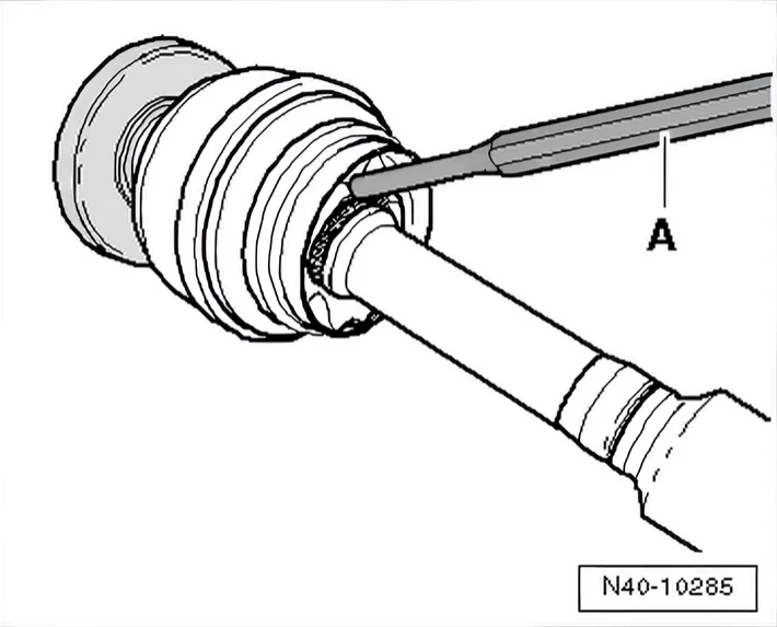
- Drive constant velocity slip joint off drive shaft using drift -A-.
Drift must be positioned exactly on triple roller spider of constant velocity joint.
Driving joint on
Tighten clip on outer joint
6R 2009–2014 Dismantling and assembling drive shaft with triple roller joint AAR 2000/108
Special tools and workshop equipment required
- Hose clip pliers - V.A.G 1275-
- Torque wrench - V.A.G 1331-
- Clamp tensioner - V.A.G 1682-
- Multi-purpose tool - VW 771-
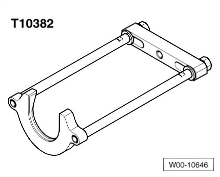
- Puller - T10382-
Removing outer constant velocity joint
- Clamp drive shaft in vice using jaw protectors.
- Fold back boot.
- Set puller - T10382- up so that smooth side of puller plate - T10382/1- points to spindles - T10382/2-.
- Assemble puller - T10382- complete with multi-purpose tool - VW 771-.
- Pull constant velocity joint from drive shaft with puller - T10382- and multi-purpose tool - VW 771-.
- 1 Puller plate - T10382/1-
- 2 Spindles - T10382/2-
Driving on outer constant velocity joint
Installation position of dished spring and spacer ring on outer joint
- 1 Dished spring
Make sure that deflector ring -1- is clipped completely onto outer joint.
- Position clamp tensioner - V.A.G 1682- as shown in illustration. Ensure jaws of tensioner lie in corners -arrows B- of ear on O-type clip.
- Tighten clip by turning spindle with a torque wrench (do not cant pliers).
Dismantling triple roller joint
- Open clamp on joint and slide back boot.
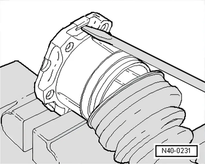
- Open out plate tabs on cover with a screwdriver and lever off cover.
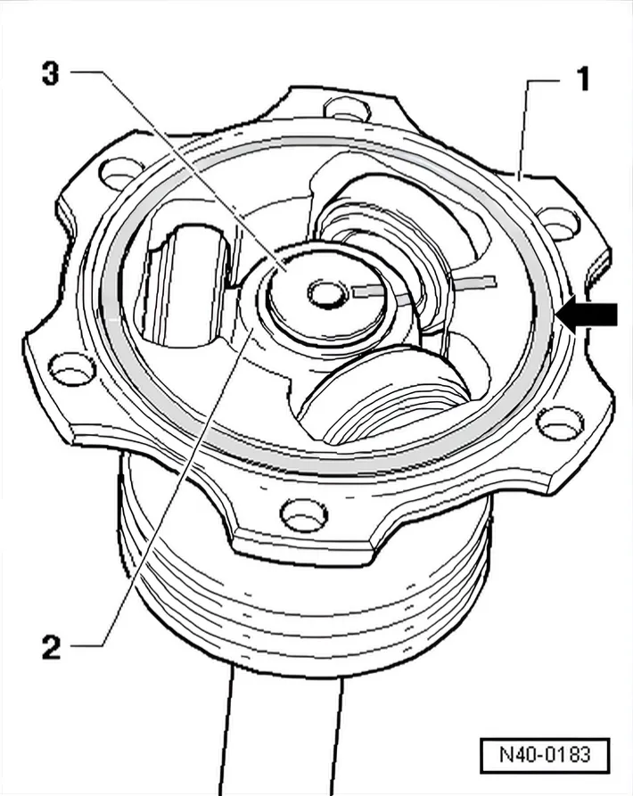
- Mark installation position of parts -1…3- with lines.
If the parts are not marked and installed in their previous positions when assembled, noises develop during may subsequent vehicle operation.
Use a waterproof felt-tip pen for marking.
- 1 Joint body
- 2 Triple roller star
- 3 Drive shaft
- Take oil seal -arrow- out of groove.
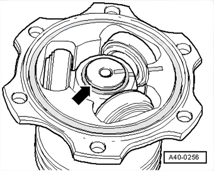
- Remove retaining ring -arrow-.
- Hold joint body and take drive shaft out of vice.
- Insert drive shaft in press.
- Hold drive shaft securely and press triple roller star off drive shaft.
- Remove triple roller star with rollers and place on a clean surface.
- Pull joint off drive shaft.
- Pull boot off shaft.
- Clean shaft and joint.
Installing
- Push protective boot for inner joint onto shaft.
- Push joint body onto shaft.
Fitting triple roller star
Chamfer on triple roller star faces towards shaft and serves as an assembly aid.
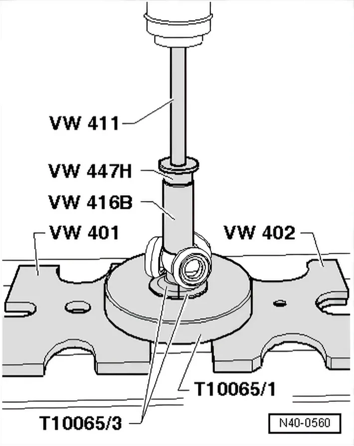
- Fit triple roller star onto shaft according to previously made markings and press on to stop.
- Insert retaining ring, ensuring that it is seated correctly.
- Slide joint body over rollers and hold.
- Press half the specified quantity of drive shaft grease from the repair kit into the triple roller joint.
- Press the other half of the specified quantity of drive shaft grease from the repair kit into the back of the triple roller joint.
- Install joint boot.
The bead in the protective boot must engage in the groove on the joint body.
- Now take drive shaft out of vice and clamp joint body in position in vice.
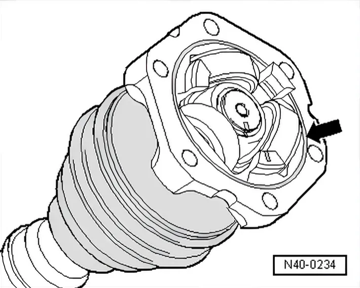
- Insert new seal -arrow- from repair kit into groove.
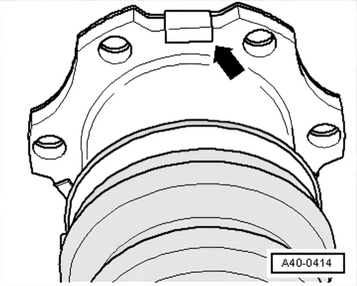
- Attach new cover to joint body - in doing so, position tabs on straight surfaces of joint body -arrow-.
The holes of the cover and joint must align.
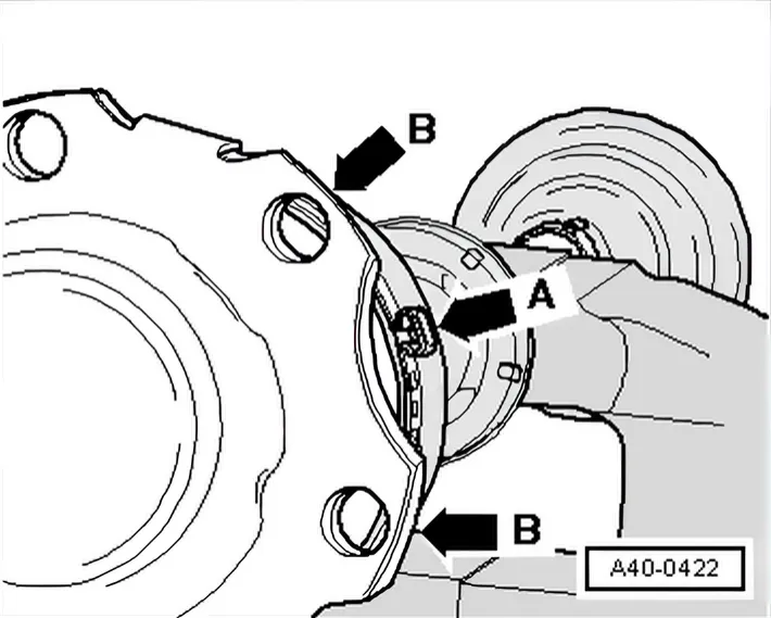
- Fit hose clip.
Clamping lug of clip -arrow A- must be located between securing flanges of joint body -arrows B-. This enables multi-point socket head bolts to be threaded in more easily when installing drive shaft.
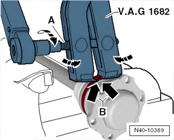
- Position clamp tensioner - V.A.G 1682- as shown in illustration. Ensure jaws of tensioner lie in corners -arrows B- of ear on O-type clip.
- Tighten clip by turning spindle with a torque wrench (do not cant pliers).