
Running gear, axles, steering · Front suspension · Drive shaft
Drive shaft – assembly overview and fastening
⇒ 6.2.1 Assembly overview – drive shaft, joint body TS1800
⇒ 6.2.2 Assembly overview – drive shaft, constant velocity joints VL90 and VL100
⇒ 6.2.3 Assembly overview – drive shaft, constant velocity joint VL107, threaded connection
⇒ 6.2.4 Assembly overview – drive shaft, constant velocity joint VL107, plug-in connection
6C 2014–2017 6.2.1 Assembly overview – drive shaft, joint body TS1800
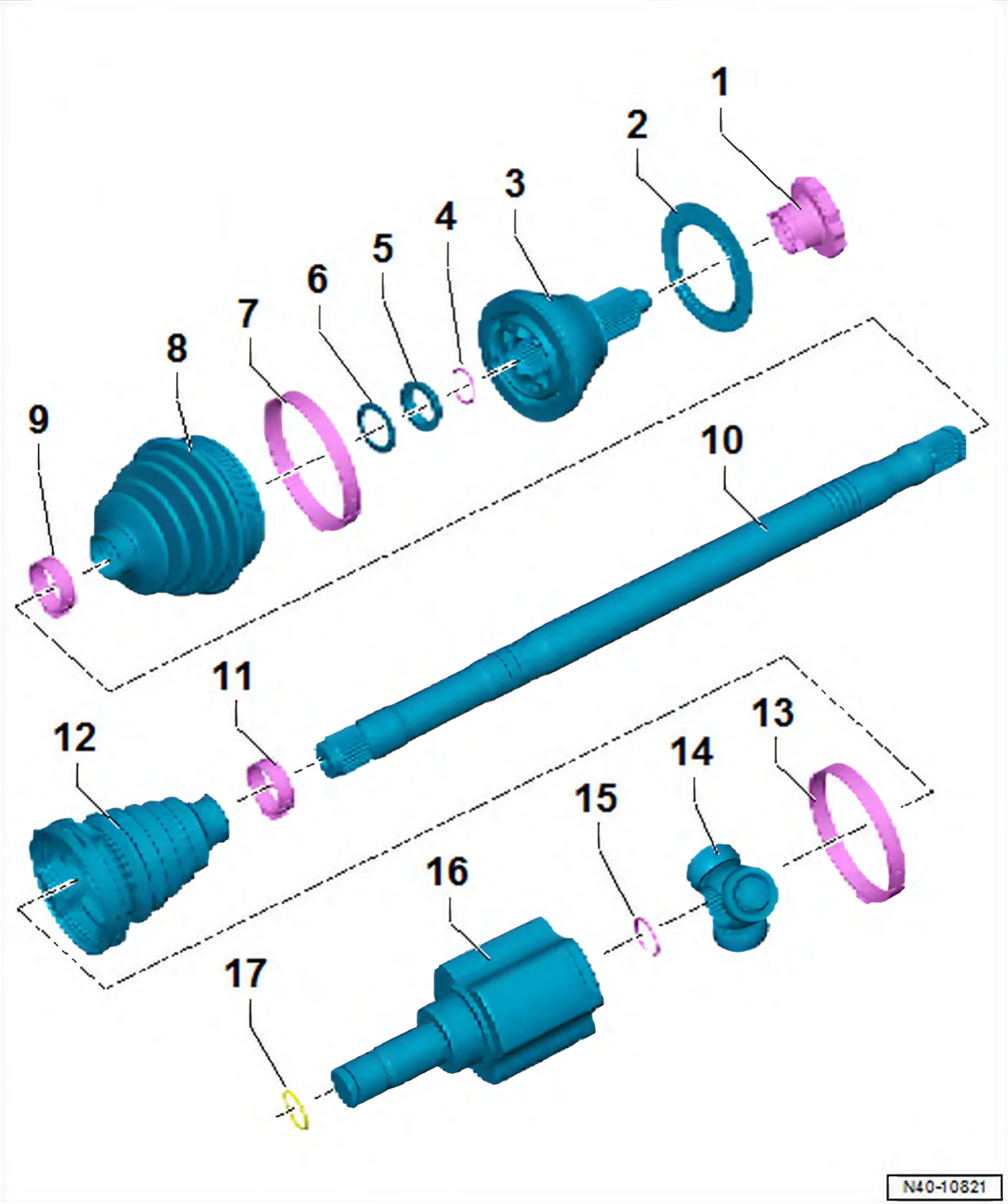
- 1 12-point nut
- Self-locking
- Renew after each removal
- Remove any corrosion on the thread of the outer joint before the nut is screwed on.
- 50 Nm +45°
- 2 Deflector ring
- Ensure deflector ring is seated correctly before installing drive shaft ⇒ 6.6.1 Dismantling and assembling drive shaft, joint body TS1800.
- 3 Outer constant velocity joint
- Renew only as complete unit
- Removing ⇒ 6.6.1 Dismantling and assembling drive shaft, joint body TS1800
- Installing: drive onto shaft with plastic hammer until compressed retaining ring seats
- Checking ⇒ 6.7 Checking outer constant velocity joint
- 4 Retaining ring
- Insert in groove in shaft
- 5 Spacer ring
- Fitting position ⇒ 6.6.1 Dismantling and assembling drive shaft, joint body TS1800
- 6 Dished spring
- Fitting position ⇒ 6.6.1 Dismantling and assembling drive shaft, joint body TS1800
- 7 Clip
- Renew after each removal
- Various versions
- Allocation ⇒ Electronic parts catalogue “ETKA”
- Tightening ⇒ 6.6.1 Dismantling and assembling drive shaft, joint body TS1800
- 8 Boot for constant velocity joint
- Check for splits and chafing
- Material: Hytrel (polyester elastomer)
- Coat sealing surface of constant velocity joint with -D 454 300 A2- before installing.
- 9 Clip
- Renew after each removal
- Tightening ⇒ 6.6.1 Dismantling and assembling drive shaft, joint body TS1800
- 10 Drive shaft
- 11 Clip
- Renew after each removal
- Tightening ⇒ 6.6.1 Dismantling and assembling drive shaft, joint body TS1800
- 12 Boot for triple roller joint
- Check for splits and chafing
- 13 Clip
- Renew after each removal
- Tightening ⇒ 6.6.1 Dismantling and assembling drive shaft, joint body TS1800
- 14 Triple roller star with rollers
The chamfer -arrow- points towards drive shaft splines.
- 15 Retaining ring
- Renew after each removal
- 16 Joint body
- Removing and installing ⇒ 6.4 Removing and installing joint body
- 17 Retaining ring
- Insert in groove in joint body.
6.2.2 Assembly overview – drive shaft, constant velocity joints VL90 and VL100
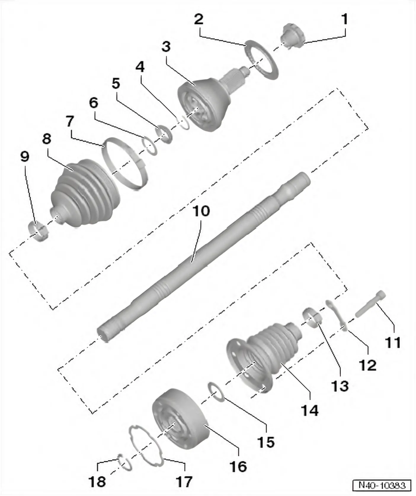
- 1 12-point nut
- Self-locking
- Renew after each removal
- Remove any corrosion on the thread of the outer joint before the nut is screwed on.
- 50 Nm +45°
- 2 Deflector ring
- Ensure deflector ring is seated correctly before installing drive shaft ⇒ 6.6.2 Dismantling and assembling drive shaft, constant velocity joints VL90 and VL100.
- 3 Outer constant velocity joint
- Renew only as complete unit
- Removing ⇒ 6.6.2 Dismantling and assembling drive shaft, constant velocity joints VL90 and VL100
- Installing: drive onto shaft to stop using plastic hammer
- Checking ⇒ 6.7 Checking outer constant velocity joint
- 4 Retaining ring
- Renew after each removal
- Insert in groove in shaft
- 5 Spacer ring
- 6 Dished spring
- 7 Clip
- Renew after each removal
- Various versions
- Allocation ⇒ Electronic parts catalogue “ETKA”
- Tensioning, version 1 ⇒ 6.6.2 Dismantling and assembling drive shaft, constant velocity joints VL90 and VL100
- Tensioning, version 2 ⇒ 6.6.2 Dismantling and assembling drive shaft, constant velocity joints VL90 and VL100
- 8 Boot
- Check for splits and chafing
- Coat sealing surface of constant velocity joint with -D 454 300 A2- before installing.
- 9 Clip
- Renew after each removal
- Tightening ⇒ 6.6.2 Dismantling and assembling drive shaft, constant velocity joints VL90 and VL100
- 10 Drive shaft
- 11 Multi-point socket head bolt
- Pre-tighten diagonally to 10 Nm
- M8 x 48;
- Renew after each removal
- 40 Nm
- 12 Locking plate
- 13 Clip
- Renew after each removal
- Tightening ⇒ 6.6.2 Dismantling and assembling drive shaft, constant velocity joints VL90 and VL100
- 14 Boot for inner constant velocity joint
- Check for splits and chafing
- Drive off with drift
- 15 Dished spring
- Splines in inner diameter
- Installation position: larger ∅ (concave side) contacts constant velocity joint
- 16 Inner constant velocity joint
- Renew only as complete unit
- Pressing off ⇒ 6.6.2 Dismantling and assembling drive shaft, constant velocity joints VL90 and VL100
- Pressing on ⇒ 6.6.2 Dismantling and assembling drive shaft, constant velocity joints VL90 and VL100
- Checking ⇒ 6.8 Checking inner constant velocity joint
- 17 Seal
- Renew: Pull off protective foil and stick onto joint.
- 18 Retaining ring
- Renew after each removal
- Remove and install using -VW 161 A-
6.2.3 Assembly overview – drive shaft, constant velocity joint VL107, threaded connection
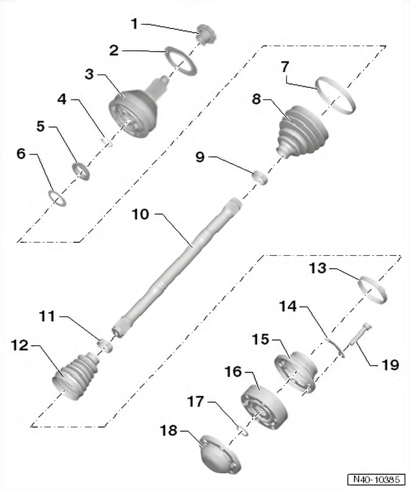
- 1 12-point nut
- Self-locking
- Renew after each removal
- Remove any corrosion on the thread of the outer joint before the nut is screwed on.
- 50 Nm +45°
- 2 Deflector ring
- Ensure deflector ring is seated correctly before installing drive shaft ⇒ 6.6.3 Dismantling and assembling drive shaft, constant velocity joint VL107, threaded connection.
- 3 Outer constant velocity joint
- Renew only as complete unit
- Removing ⇒ 6.6.3 Dismantling and assembling drive shaft, constant velocity joint VL107, threaded connection
- Installing: drive onto shaft to stop using plastic hammer
- Checking ⇒ 6.7 Checking outer constant velocity joint
- 4 Retaining ring
- Renew after each removal
- Insert in groove in shaft
- 5 Spacer ring
- 6 Dished spring
- 7 Clip
- Renew after each removal
- Various versions
- Allocation ⇒ Electronic parts catalogue “ETKA”
- Tensioning, version 1 ⇒ 6.6.3 Dismantling and assembling drive shaft, constant velocity joint VL107, threaded connection
- Tensioning, version 2 ⇒ 6.6.3 Dismantling and assembling drive shaft, constant velocity joint VL107, threaded connection
- 8 Boot
- Check for splits and chafing
- Material: Hytrel (polyester elastomer)
- 9 Clip
- Renew after each removal
- Tightening ⇒ 6.6.3 Dismantling and assembling drive shaft, constant velocity joint VL107, threaded connection
- 10 Drive shaft
- 11 Clip
- Renew after each removal
- Tightening ⇒ 6.6.3 Dismantling and assembling drive shaft, constant velocity joint VL107, threaded connection
- 12 Boot for constant velocity joint
- Material: Hytrel (polyester elastomer)
- Without breather hole
- Check for splits and chafing
- Drive off constant velocity joint with a drift
- Coat sealing surface of constant velocity joint with -D 454 300 A2- before installing.
- 13 Clip
- Renew after each removal
- Tightening ⇒ 6.6.3 Dismantling and assembling drive shaft, constant velocity joint VL107, threaded connection
- 14 Locking plate
- 15 Cap
- Drive off carefully with drift
- Coat sealing surface of constant velocity joint with -D 454 300 A2- before installing.
- Adhesive surface must be free of oil and grease!
- 16 Inner constant velocity joint
- Renew only as complete unit
- Pressing off ⇒ 6.6.3 Dismantling and assembling drive shaft, constant velocity joint VL107, threaded connection
- Pressing on ⇒ 6.6.3 Dismantling and assembling drive shaft, constant velocity joint VL107, threaded connection
- Checking ⇒ 6.8 Checking inner constant velocity joint
- 17 Retaining ring
- 18 Cover
- Renew after each removal
- Pressing off ⇒ 6.6.3 Dismantling and assembling drive shaft, constant velocity joint VL107, threaded connection
- 19 Multi-point socket head bolt
- Pre-tighten diagonally to 10 Nm
- M10 x 52
- Always renew bolts after removing
- 70 Nm
6C 2014–2017 6.2.4 Assembly overview – drive shaft, constant velocity joint VL107, plug-in connection
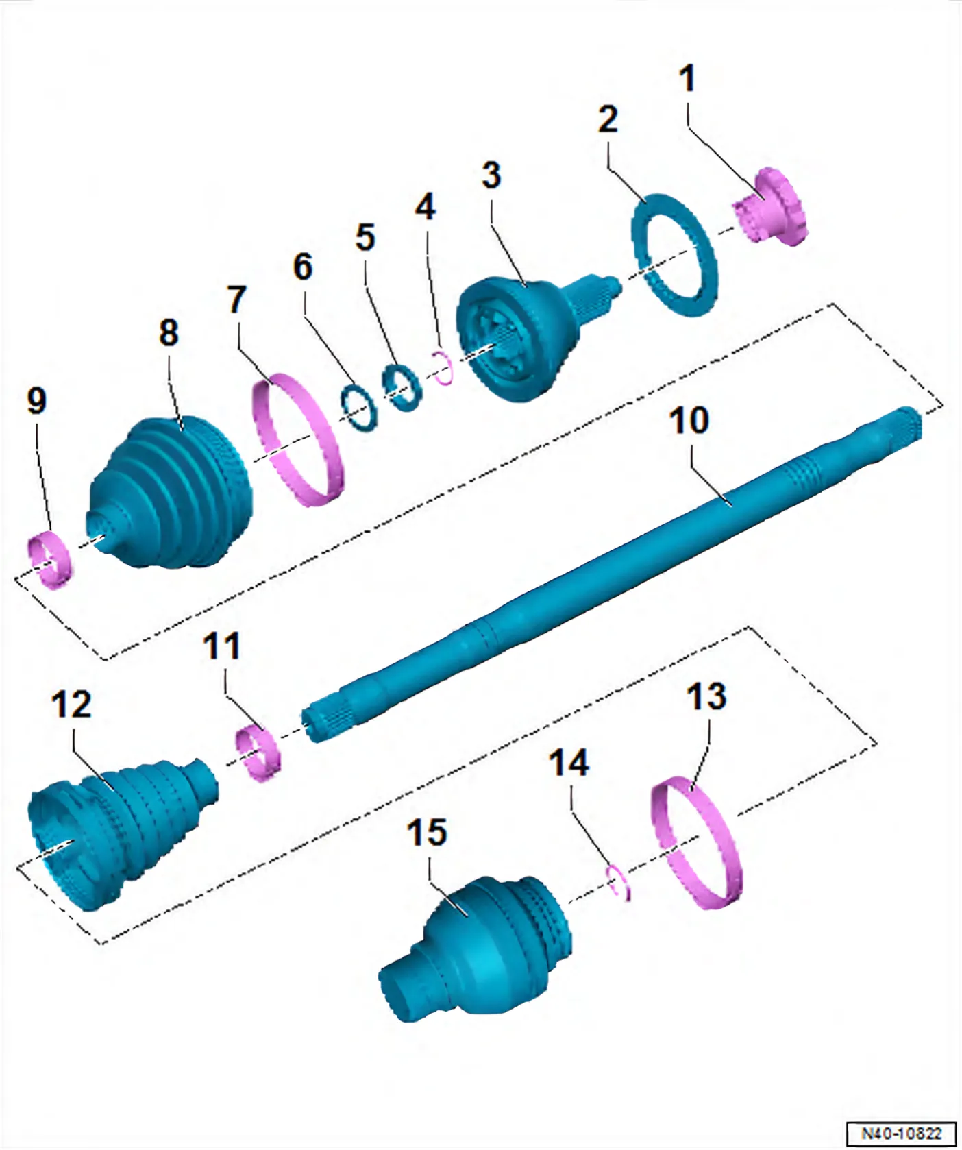
- 1 12-point nut
- Self-locking
- Renew after each removal
- Remove any corrosion on the thread of the outer joint before the nut is screwed on.
- 50 Nm +45°
- 2 Deflector ring
- Ensure deflector ring is seated correctly before installing drive shaft ⇒ 6.6.4 Dismantling and assembling drive shaft, constant velocity joint VL107, plugin connection.
- 3 Outer constant velocity joint
- Renew only as complete unit
- Removing ⇒ 6.6.2 Dismantling and assembling drive shaft, constant velocity joints VL90 and VL100
- Installing: drive onto shaft to stop using plastic hammer
- Checking ⇒ 6.7 Checking outer constant velocity joint
- 4 Retaining ring
- Renew after each removal
- Insert in groove in shaft
- 5 Spacer ring
- 6 Dished spring
- 7 Clip
- Renew after each removal
- Tightening ⇒ 6.6.4 Dismantling and assembling drive shaft, constant velocity joint VL107, plugin connection
- 8 Boot
- Check for splits and chafing
- Material: Hytrel (polyester elastomer)
- 9 Clip
- Renew after each removal
- Tightening ⇒ 6.6.3 Dismantling and assembling drive shaft, constant velocity joint VL107, threaded connection
- 10 Drive shaft
- 11 Clip
- Renew after each removal
- Tightening ⇒ 6.6.3 Dismantling and assembling drive shaft, constant velocity joint VL107, threaded connection
- 12 Boot for constant velocity slip joint
- Material: Hytrel (polyester elastomer)
- Without breather hole
- Check for splits and chafing
- 13 Clip
- Renew after each removal
- Tightening ⇒ 6.6.4 Dismantling and assembling drive shaft, constant velocity joint VL107, plugin connection
- 14 Retaining ring
- Renew after each removal
- Insert in groove in shaft
- 15 Constant velocity slip joint
- Renew only as complete unit
- Removing ⇒ 6.6.4 Dismantling and assembling drive shaft, constant velocity joint VL107, plugin connection
- Installing: drive onto shaft to stop using plastic hammer
6R 2009–2014 Assembly overview: drive shaft with triple roller joint AAR 2000/108
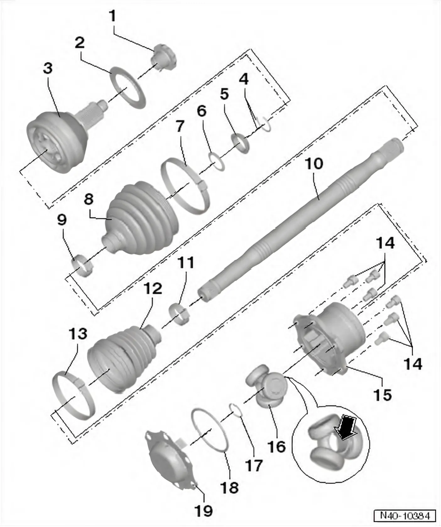
- 1 12-point nut
- Self-locking
- 50 Nm and turn 45° further
- Renew after each removal
- Remove any corrosion on the thread of the outer joint before the nut is screwed on.
- 2 Deflector ring
- Ensure deflector ring is seated correctly before installing drive shaft ⇒ 10.1 Dismantling and assembling drive shaft with triple roller joint AAR 2000/108.
- 3 Outer constant velocity joint
- Renew only as complete unit
- Removing ⇒ 10.1 Dismantling and assembling drive shaft with triple roller joint AAR 2000/108
- Installing: drive onto shaft with plastic hammer until compressed retaining ring seats
- Checking ⇒ 8.2 Checking outer constant velocity joint
- 4 Retaining ring
- Insert in groove in shaft
- 5 Spacer ring
- 6 Dished spring
- 7 Clip
- Renew after each removal
- Various versions
- Allocation ⇒ Electronic parts catalogue “ETKA”
- Tensioning, variant 1 ⇒ 10.1 Dismantling and assembling drive shaft with triple roller joint AAR 2000/108
- Tensioning, variant 2 ⇒ 10.1 Dismantling and assembling drive shaft with triple roller joint AAR 2000/108
- 8 Boot for constant velocity joint
- Check for splits and chafing
- Material: Hytrel (polyester elastomer)
- Coat sealing surface of constant velocity joint with -D 454 300 A2- before installing.
- 9 Clip
- Renew after each removal
- Tightening ⇒ 10.1 Dismantling and assembling drive shaft with triple roller joint AAR 2000/108
- 10 Drive shaft
- 11 Clip
- Renew after each removal
- Tightening ⇒ 10.1 Dismantling and assembling drive shaft with triple roller joint AAR 2000/108
- 12 Boot for triple roller joint
- Check for splits and chafing
- 13 Clip
- Renew after each removal
- Tightening ⇒ 10.1 Dismantling and assembling drive shaft with triple roller joint AAR 2000/108
- 14 Multi-point socket head bolt
- Pre-tighten diagonally to 10 Nm
- M 10 x 23; 70 Nm.
- Renew after each removal
- 15 Joint body
- Outside diameter: 108 mm
- 16 Triple roller star with rollers
The chamfer -arrow- points towards drive shaft splines.
- 17 Retaining ring
- Renew after each removal
- 18 Seal
- Renew after each removal
- 19 Cover
- Renew after each removal