
Running gear, axles, steering · Front suspension · Drive shaft
Removing and installing drive shaft
6R 2009–2014 Removing and installing drive shafts with triple roller joint AAR 2000 (bolted-on) ⇒ 6.2 Removing and installing drive shaft with triple roller joint AAR 2000 (bolted-on).
6C 2014–2017 ⇒ 6.3.1 Removing and installing drive shaft, joint body TS1800
⇒ 6.3.2 Removing and installing drive shaft, constant velocity joint, threaded connection
6R 2009–2014 Removing and installing drive shaft with constant velocity joint ⇒ 6.1 Removing and installing drive shaft with constant velocity joint.
6C 2014–2017 ⇒ 6.3.3 Removing and installing drive shaft, constant velocity joint, plug-in connection
6.3.1 Removing and installing drive shaft, joint body TS1800
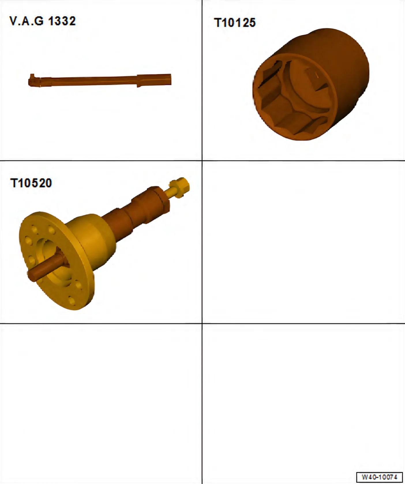
Special tools and workshop equipment required
- Torque wrench - V.A.G 1332-
- 36 mm socket - T10125-
- Ejector - T10520-
If wheel bearings are loaded with weight of vehicle, wheel bearings will be damaged and service life of wheel bearings will be considerably reduced.
It is not permissible to loosen drive shaft bolt more than 90° if vehicle is standing on its wheels.
Do not attempt to move the vehicle without the drive shafts fitted as this would damage the wheel bearing. If a vehicle must nevertheless be moved, comply with the following:
- Install an outer joint instead of the drive shaft.
- Tighten outer joint to 120 Nm.
Removing
- Lift vehicle far enough to take weight off front axle.
- Unscrew twelve-point nut for drive shaft.
- Loosen wheel bolts.
- Raise vehicle.
- Remove wheel.
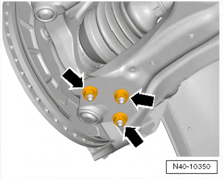
- Remove nuts -arrows-
- Pull swivel joint out of suspension link.
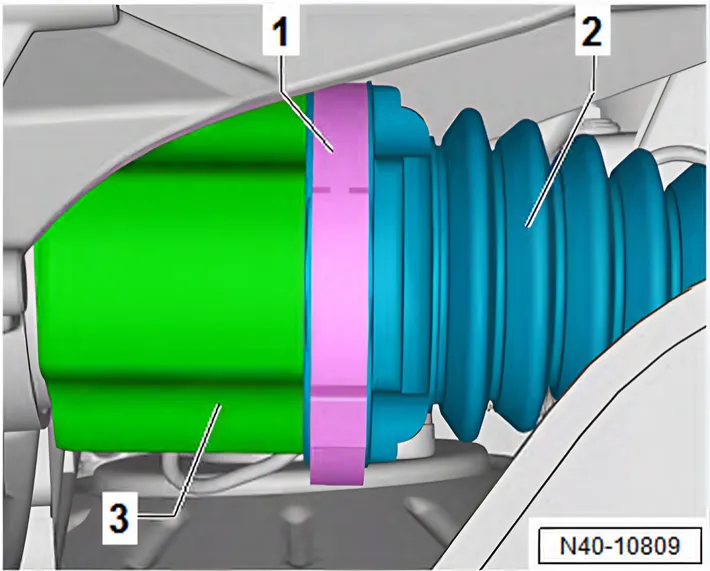
- Open clamp -1-.
- Push bellows -2- off joint body -3-.
- Pull drive shaft out of joint body.
- Pull drive shaft out of wheel bearing and remove.
If the drive shaft cannot be pulled out of the wheel bearing by hand, use ejector - T10520-.
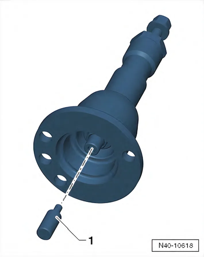
Before using pressure tool - T10520-, make sure that thrust piece -1- is inserted.
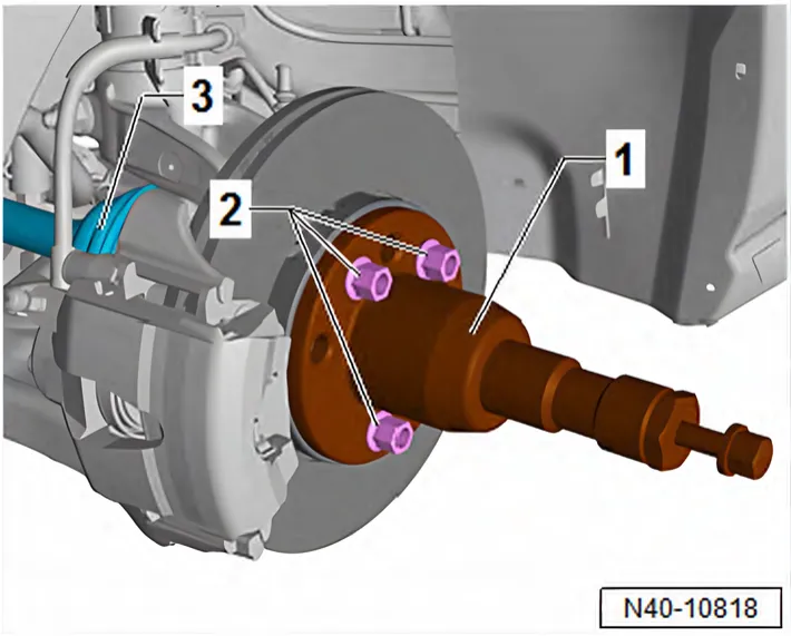
Using ejector - T10520- :
- To press out drive shaft -3-, secure ejector - T10520- -1- to wheel hub using 3 wheel bolts -2-.
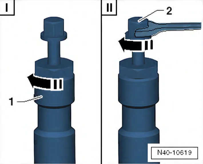
- It is essential to follow specified sequence.
I - Tighten knurled nut -1- hand-tight.
II - Using spanner, turn only bolt -2-, not the press tool itself. Pull out drive shaft using press tool - T10520-.
Installing
Remove any paint residues and/or corrosion on thread and splines of outer joint.
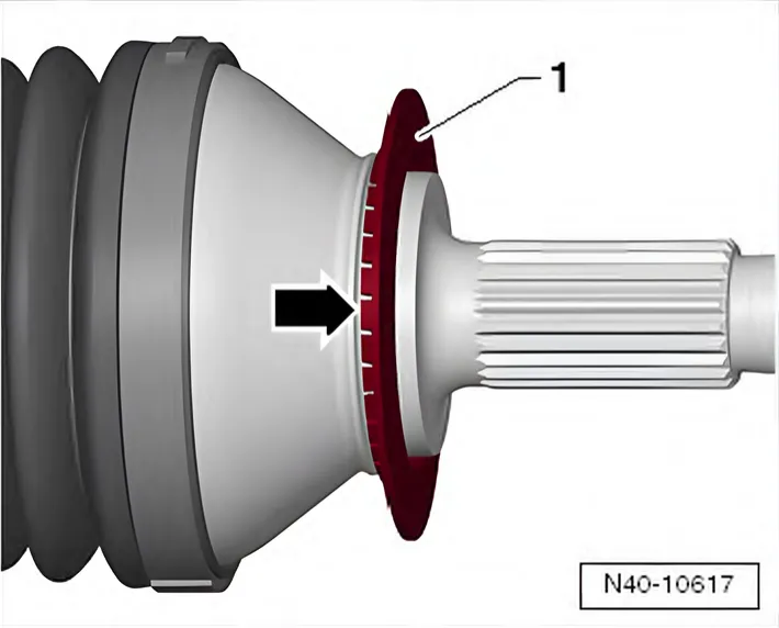
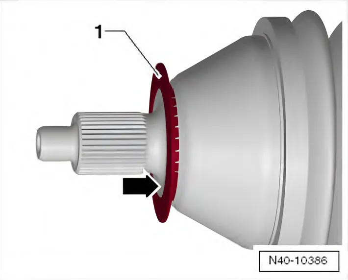
Make sure that deflector ring -1- is clipped completely onto outer joint.
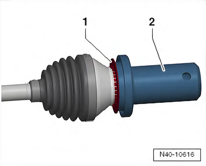
- Lightly coat thread and splines of stub axle and contact surfaces of wheel hub/twelve-point nut with pressure-resistant oil Fuchs Renolin B15 VG46.
- Guide outer joint into wheel hub splines as far as possible.
- Secure outer joint in wheel hub splines with 12-point nut of drive shaft.
- Push drive shaft into joint body.
- Press half the drive shaft grease from the repair kit into the joint body.
- Press remaining drive shaft grease from the repair kit into the bellows.
- Push bellows -2- onto joint body -3-.
- Fit new clamp -1- in position.
- Tightening hose clip ⇒ 6.6.1 Dismantling and assembling drive shaft, joint body TS1800
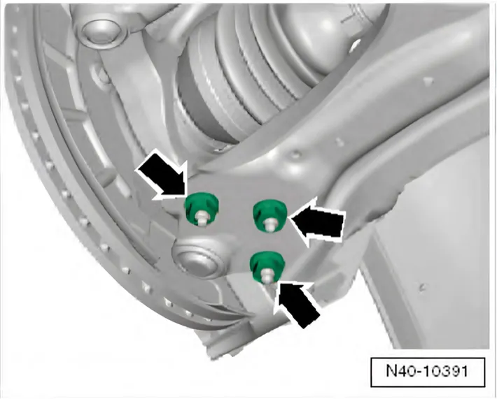
- Bolt swivel joint to suspension link with new nuts -arrows-.
Use new nuts!
Ensure that boot is not damaged or twisted.
- Install wheel and tighten bolts or nuts ⇒ 1.5 Specified torques for wheel bolts.
- Tighten twelve-point nut for drive shaft.
Specified torques
| Component | Specified torque |
|---|---|
| 12-point nut on drive shaft ♦ Use a new nut. | 50 Nm +45° |
| 6R 2009–2014 Swivel joint to suspension link ♦ Use new nuts. | 100 Nm |
| 6C 2014–2017 Swivel joint to suspension link ♦ Use new nuts. | 40 Nm +45° |
The two manuals give different torques for the same swivel joint nuts (N10332002): 100 Nm in the Polo 6R manual, 40 Nm +45° in the Polo 6C manual. Other cars with the same swivel joints differ too: the Audi A1 8X manual gives 100 Nm, the Škoda Fabia II manual 40 Nm +45°.
6C 2014–2017
6.3.2 Removing and installing drive shaft, constant velocity joint, threaded connection
Only what differs from the procedure above; everything else is as above.
Special tools and workshop equipment required
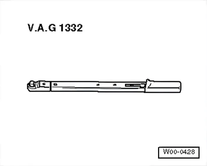
- Torque wrench - V.A.G 1331-
Removing
- Unscrew 12-point nut from drive shaft with 36 mm socket - T10125-.
- Unbolt drive shaft from gearbox flange shaft.
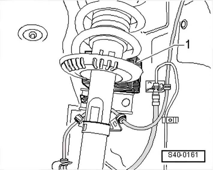
- Pivot suspension strut outwards and support with e.g. a wooden block -1-; at the same time pull drive shaft out of wheel bearing and remove outwards.
6R 2009–2014 If the drive shaft cannot be pulled out of the wheel bearing by hand, use press tool - 3283 A- or press tool - T10520-.
Installing
- Insert drive shaft.
Use new nuts!
- Fit inner joint of drive shaft in position and pre-tighten bolts in diagonal sequence to 10 Nm.
- Tighten multi-point socket-head bolts diagonally to the specified torque.
- Tighten 12-point drive shaft nut with 36 mm socket - T10125-.
Specified torques
| Component | Specified torque |
|---|---|
| 6R 2009–2014 Swivel joint to suspension link ♦ Use new bolts | 100 Nm |
| Drive shaft to flange shaft on gearbox “M8 multi-point sock‐ | 40 Nm |
| et” ♦ Use new bolts | ♦Pre-tighten diagonally to 10 Nm |
| Drive shaft to flange shaft on gearbox “M10 multi-point | 70 Nm |
| socket” ♦ Use new bolts | ♦Pre-tighten diagonally to 10 Nm |
| 12-point nut on drive shaft ♦ Use new bolts | 50 Nm +45° |
6C 2014–2017 6.3.3 Removing and installing drive shaft, constant velocity joint, plug-in connection
Only what differs from the procedure above; everything else is as above.
Removing
- Unbolt coupling rods from anti-roll bars on both sides.
- Push drive shaft outer joint out of wheel hub by hand.
- Secure press tool - T10520- -1- to wheel hub using 3 wheel bolts.
- Secure drive shaft to prevent it from falling.
- Remove lower noise insulation ⇒ General body repairs, exterior; Rep. gr. 66; Noise insulation; Assembly overview - noise insulation.
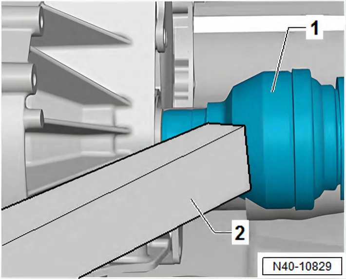
- Using suitable tool, e.g. wooden block -2-, drive the drive shaft -1- off gearbox stub shaft.
- Remove drive shaft from vehicle.
Installing
- Insert new retaining ring in groove in stub shaft on gearbox.
- Lightly grease splines of stub shaft with universal grease - G 060 735 A2-.
- Mesh outer and inner splines of gearbox and constant velocity slip joint.
- Slide drive shaft into constant velocity joint to stop by hand.
- Now push constant velocity joint onto stub shaft of gearbox with a »sudden, hard push«.
- Check that constant velocity slip joint is securely seated by pulling constant velocity slip joint against resistance of retaining ring.
- Remove tensioning strap - T10038-.
Use new nuts!
- Install lower noise insulation ⇒ General body repairs, exterior; Rep. gr. 66; Noise insulation; Assembly overview - noise insulation.
Specified torques
| Component | Specified torque |
|---|---|
| 12-point nut on drive shaft ♦ Use a new nut. | 50 Nm +45° |
| 6R 2009–2014 Swivel joint to suspension link ♦ Use new nuts. | 100 Nm |
| 6C 2014–2017 Swivel joint to suspension link ♦ Use new nuts. | 40 Nm +45° |
The two manuals give different torques for the same swivel joint nuts (N10332002): 100 Nm in the Polo 6R manual, 40 Nm +45° in the Polo 6C manual. Other cars with the same swivel joints differ too: the Audi A1 8X manual gives 100 Nm, the Škoda Fabia II manual 40 Nm +45°.
6R 2009–2014 Removing and installing drive shaft with triple roller joint AAR 2000 (bolted-on)
Only what differs from the procedure above; everything else is as above.
Special tools and workshop equipment required
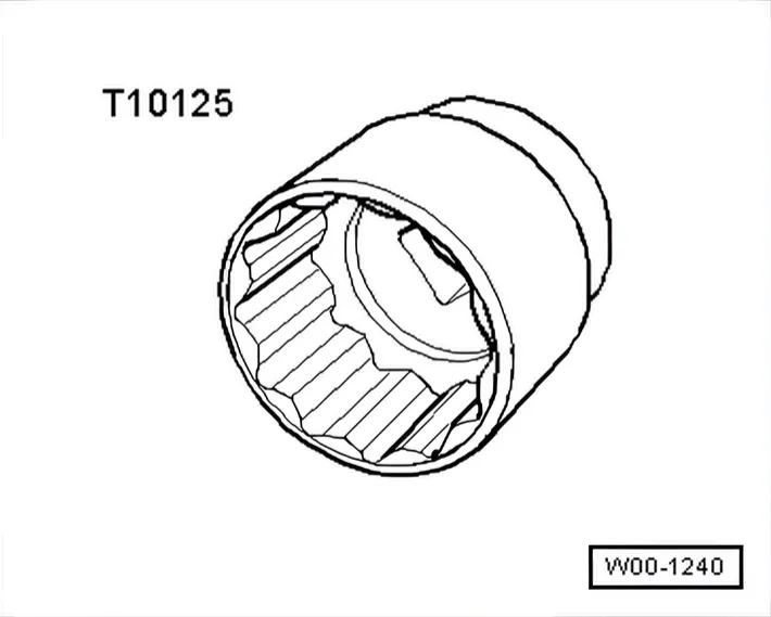
- 36 mm socket - T10125-
Removing
- Lift vehicle far enough to take weight off front axle.
- Remove wheel.
- Remove nuts -arrows-
- Pull swivel joint out of suspension link.
Installing
Remove any paint residues and/or corrosion on thread and splines of outer joint.
Make sure that deflector ring -1- is clipped completely onto outer joint.
- Guide outer joint into wheel hub splines as far as possible.
- Bolt swivel joint to suspension link with new nuts -arrows-.
Use new nuts!
Ensure that boot is not damaged or twisted.
- Install wheel and tighten bolts or nuts ⇒ 2 Specified torques for wheel bolts.
Specified torques
| Bolt | Specified torque |
|---|---|
| Swivel joint to suspension link ♦Use new bolts. | 100 Nm |
| Drive shaft to flange shaft on gearbox “M10 multi-point | 70 Nm |
| socket” ♦Use new bolts ♦Without locking plates | ♦Pre-tighten diagonally to 10 Nm |
| 12-point nut on drive shaft ♦Use new nuts. | 50 Nm + 45° |