
SSP 390 The 7-speed Double-clutch Gearbox 0AM
Hydraulic pump
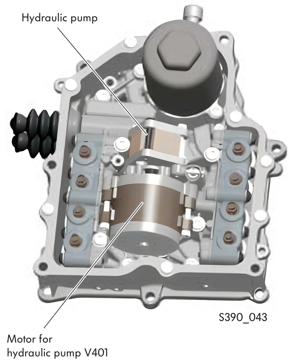
The hydraulic pump unit is located in the mechatronic module. It consists of a hydraulic pump and an electric motor.
The motor for the hydraulic pump is a brushless DC motor. It is actuated by the mechatronic unit's electronic control unit depending on pressure requirements. It drives the hydraulic pump via a coupling.
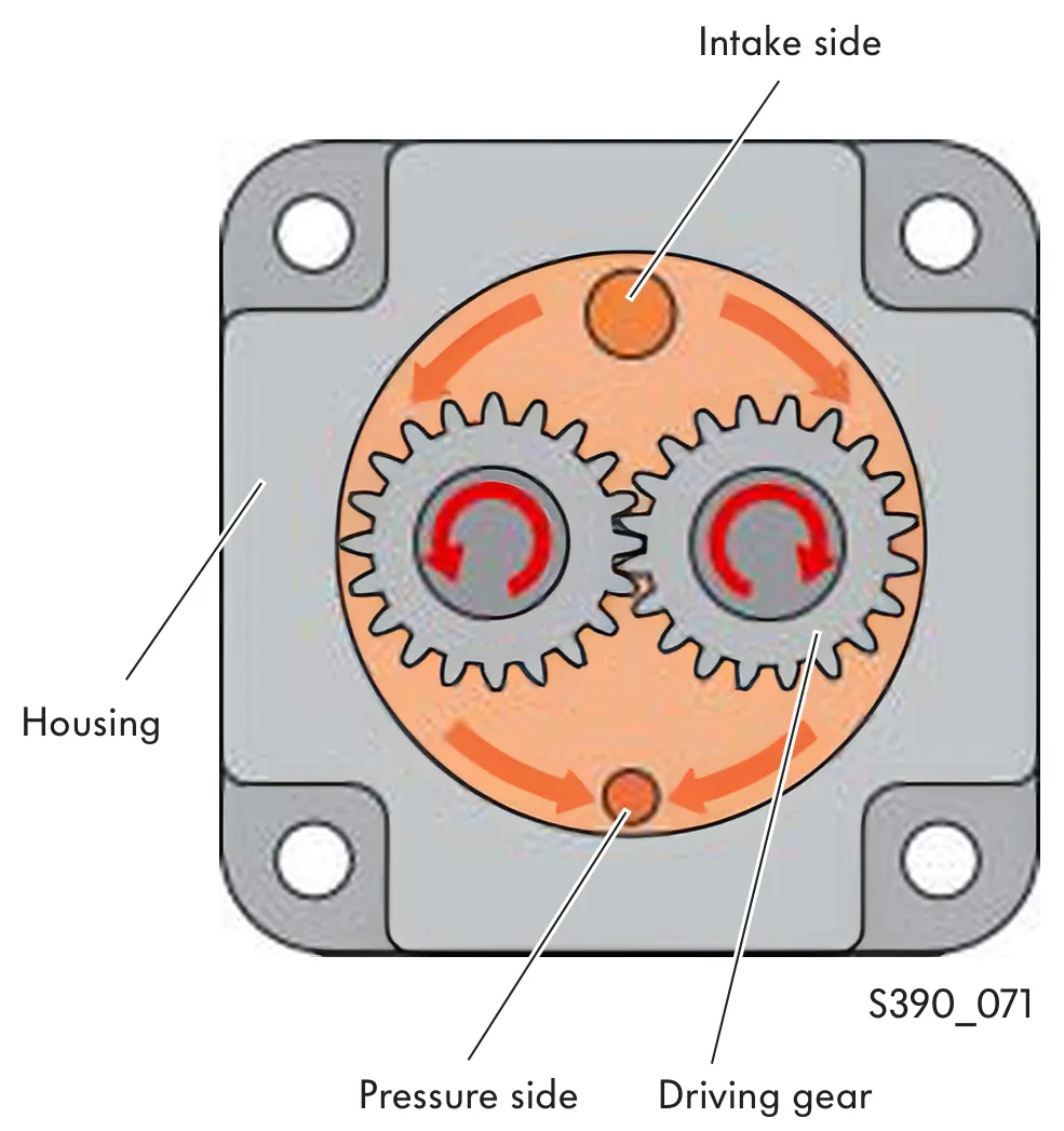
The hydraulic pump operates according to the principle of a gear pump. It intakes the hydraulic oil and pumps it into the oil circuit at a pressure of approx. 70 bar.
The hydraulic oil is pumped from the intake side to the pressure side between the walls of the pump housing and the tooth gaps.
Motor for hydraulic pump V401
Design
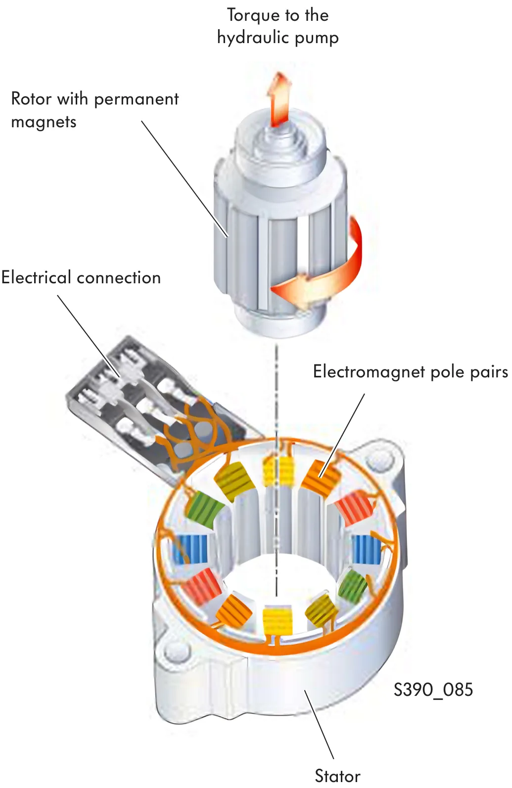
Like conventional, smaller DC electric motors, the brushless DC motor also consists of a stator and a rotor. Whilst the stator consists of permanent magnets and the rotor of electromagnets in the conventional, smaller electric motor, the opposite is true in the case of the brushless DC motor. The rotor consists of 6 permanent magnet pairs and the stator of 6 electromagnet pairs.
How it works
In the conventional DC motor, commutation (current direction change-over) takes place via ring contacts.
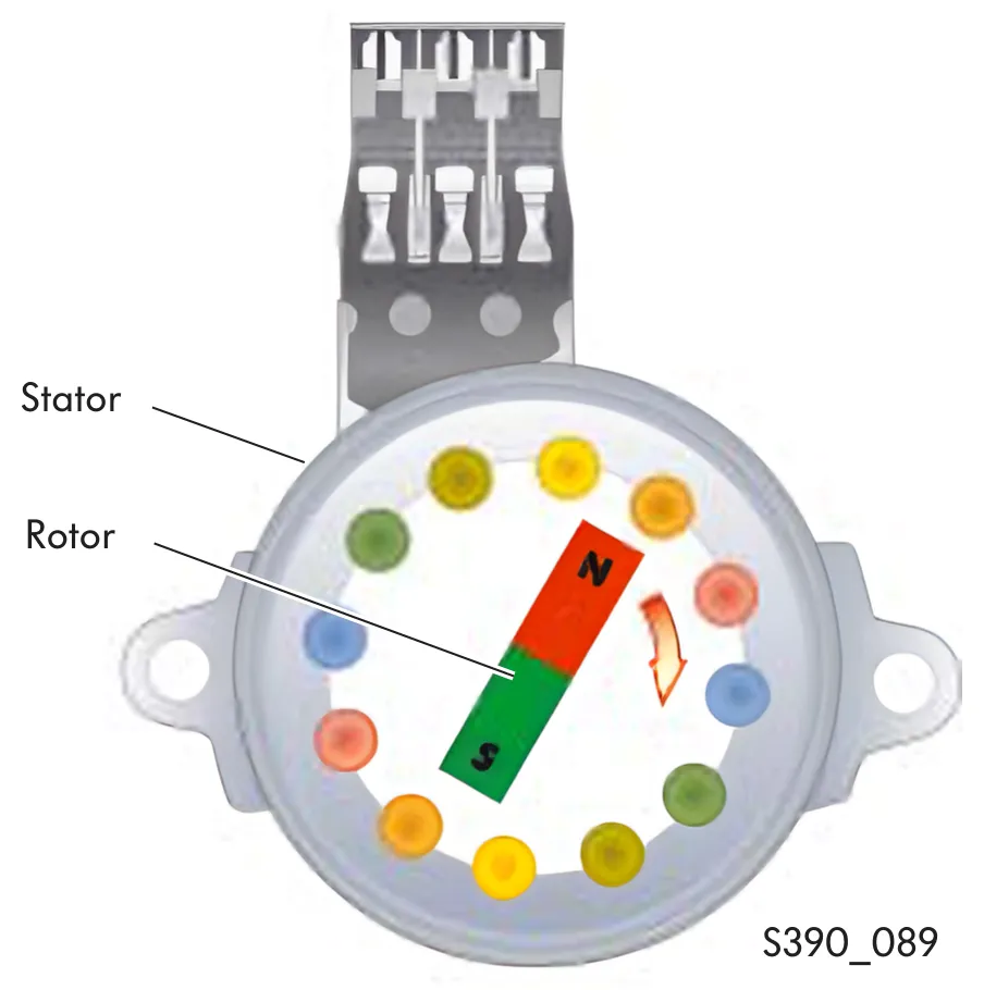
Commutation in the brushless DC motor is carried out by the mechatronic unit's electronic control unit and is therefore contact-free.
The stator coils are actuated in such a way that a rotating magnetic field occurs in the stator coils. The rotor follows this magnetic field and is therefore caused to rotate.
Thanks to contact-free commutation, the DC motor runs entirely wear-free, with the exception of bearing wear.
Electrical actuation
So that a rotational movement is carried out, the mechatronic unit control unit switches between the possible phases in the individual pole pairs within good time. The magnetic field changes. The rotor is therefore constantly compelled to turn itself and therefore carries out a rotational movement.
The schematic shows the design of the circuit using the example of a wound coil.
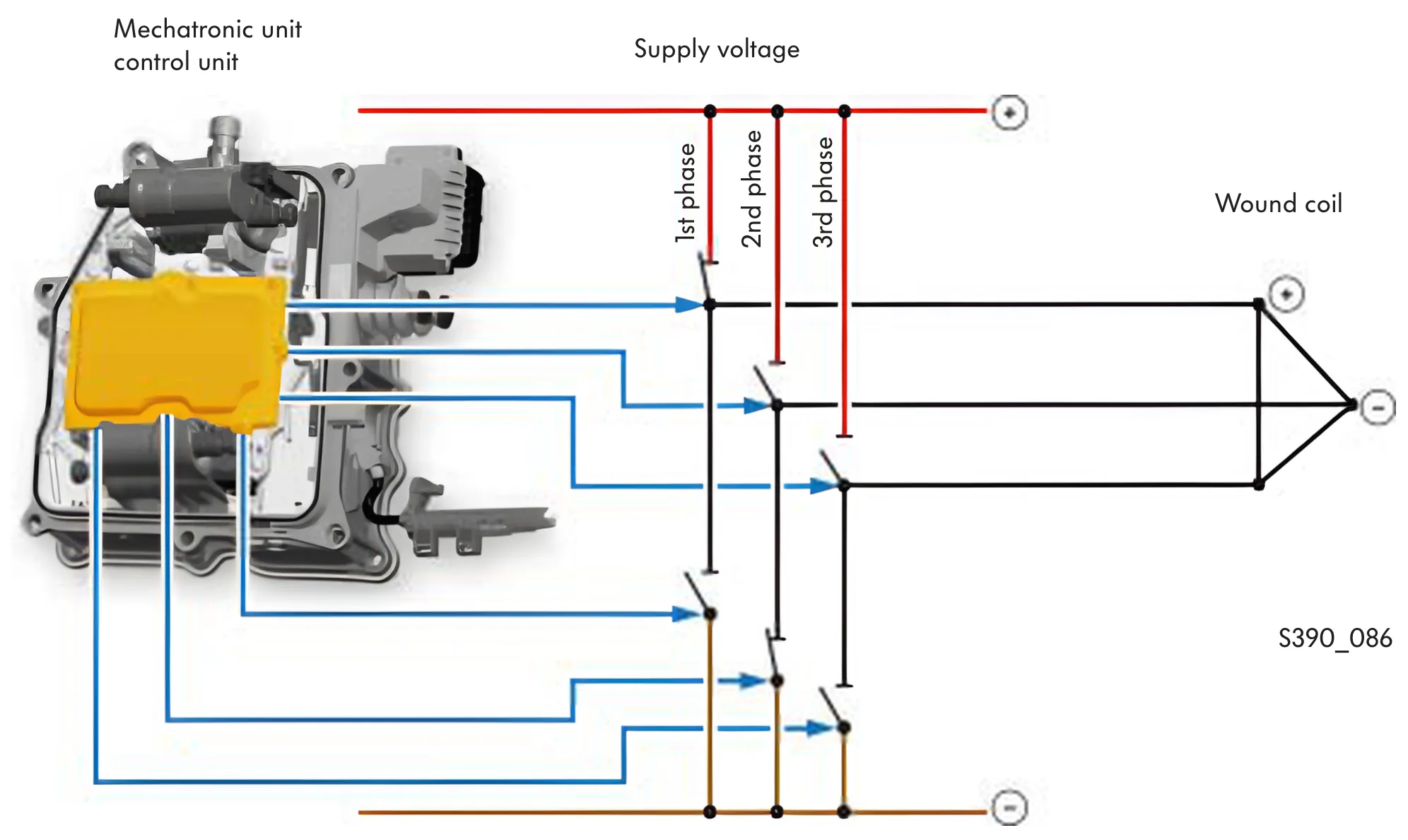
Legend
- 1st phase – positively switched
- 2nd phase – negatively switched
- 3rd phase - open
Gearbox hydraulic pressure sender G270 and pressure limiting valve
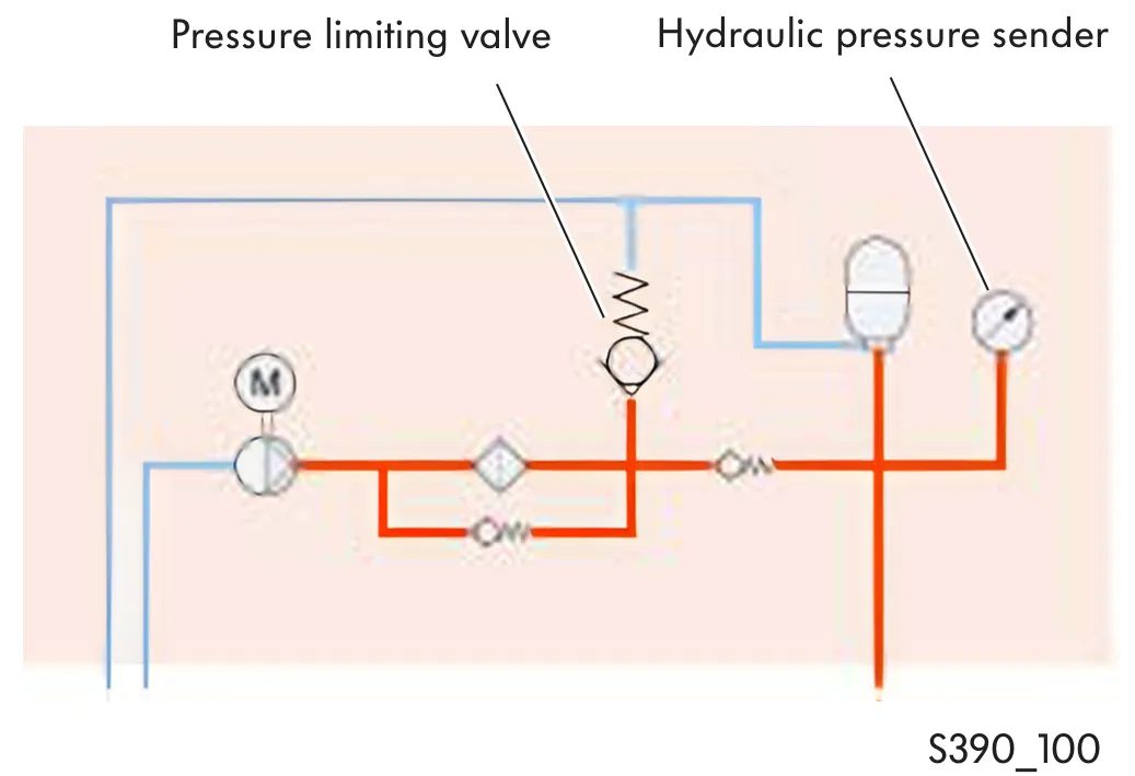
The hydraulic pump pumps the hydraulic oil through the filter towards the pressure limiting valve, the pressure accumulator and the hydraulic pressure sender. When the hydraulic oil pressure at the pressure limiting valve and the hydraulic pressure sender reaches approx. 70 bar, the control unit switches the electric motor and therefore the hydraulic pump off. The bypass ensures that the system functions if the filter channel is clogged.
Pressure accumulator
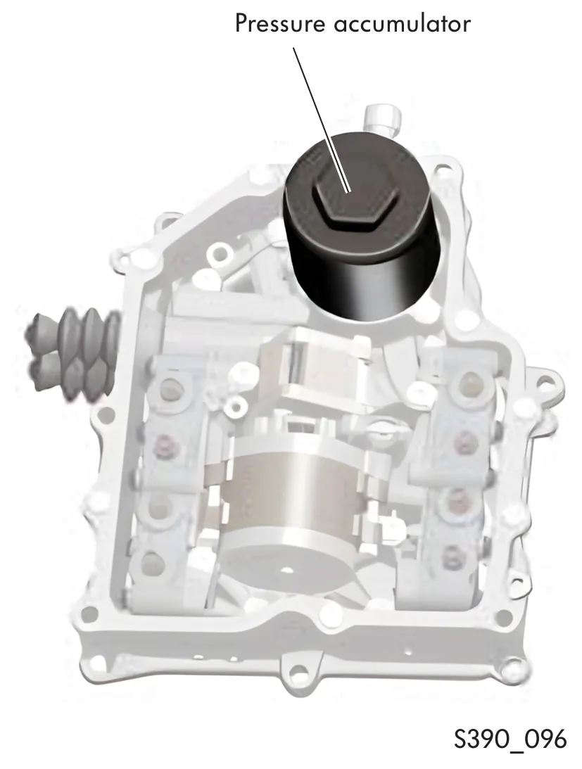
The pressure accumulator is designed as a gas pressure accumulator. It provides the hydraulic system with oil pressure when the hydraulic pump is switched off. Its storage volume is 0.2 litres.
Oil circuit flow chart
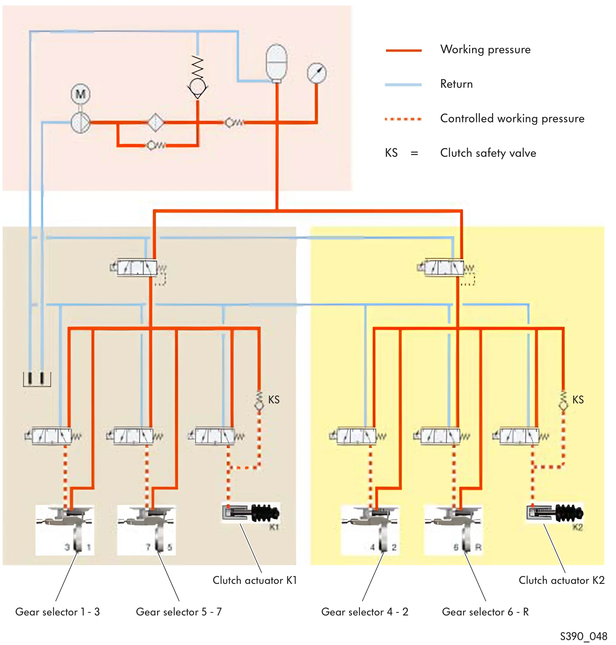
Legend
- N433 Valve 1 in gear train half 1
- N434 Valve 2 in gear train half 1
- N435 Valve 3 in gear train half 1
- N436 Valve 4 in gear train half 1
- N437 Valve 1 in gear train half 2
- N438 Valve 2 in gear train half 2
- N439 Valve 3 in gear train half 2
- N440 Valve 4 in gear train half 2
The clutch safety valves enable the clutches to be drained and therefore opened in the event of a fault.
Task and function of the solenoid valves in the oil circuit
Gear train half pressure control solenoid valves
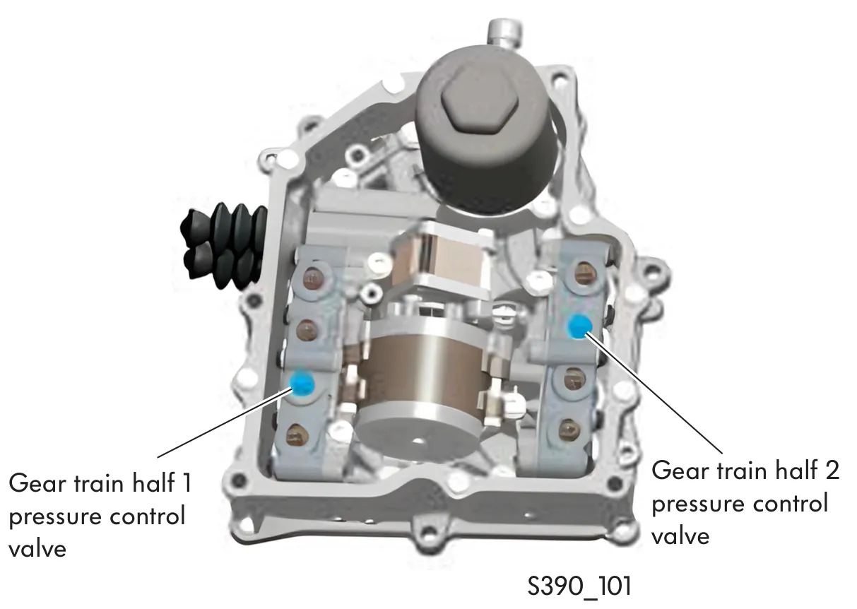
The gear train half pressure control solenoid valves control the oil pressure for gear train halves 1 and 2. If a fault is detected in a gear train half, the pressure control solenoid valve can shut off the corresponding gear train half.
Gear selector solenoid valves
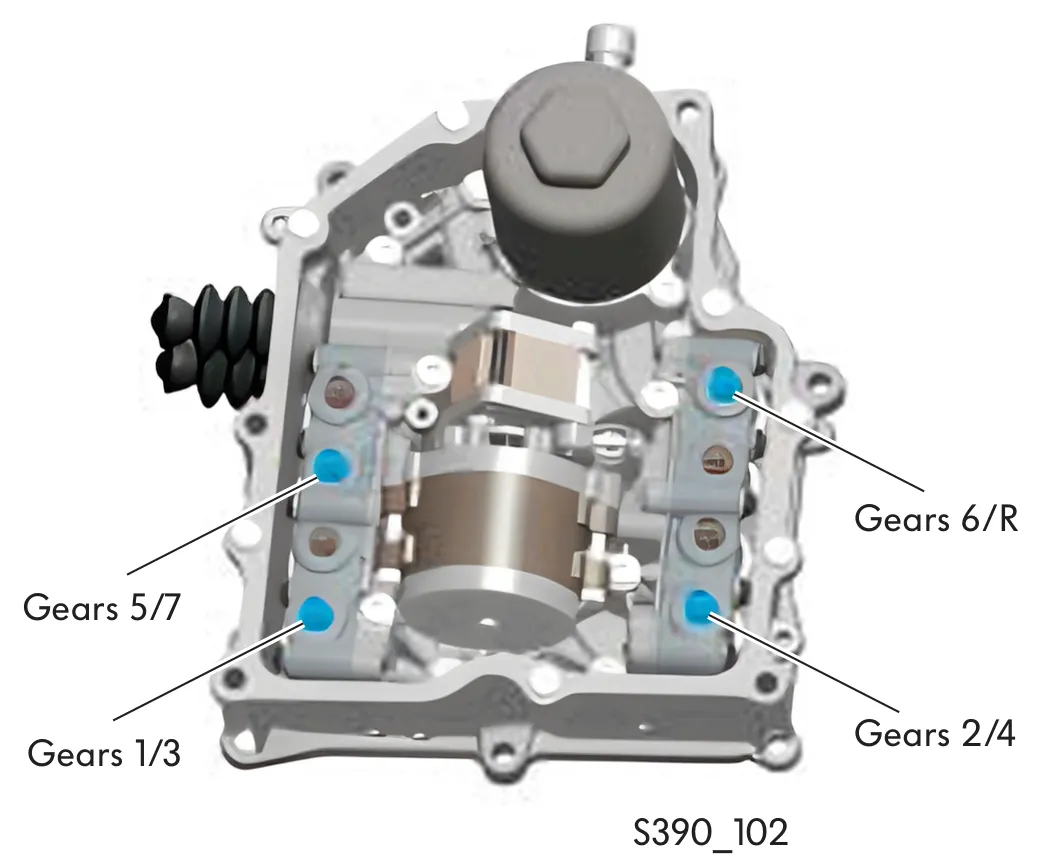
The gear selector solenoid valves control the volume of oil to the gear selectors. Each gear selector shifts 2 gears. If no gear is engaged, the gear selectors are held in the neutral position via oil pressure. In selector lever position "P" and when the ignition is switched off, 1st gear and reverse gear are engaged.
Clutch actuator solenoid valves
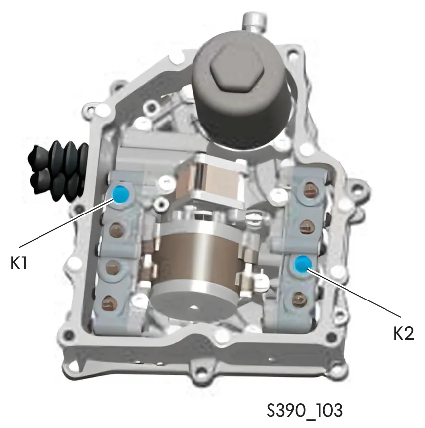
The clutch actuator solenoid valves control the volume of oil to the clutch actuators. The clutch actuators actuate clutches K1 and K2. When not supplied with current, the solenoid valves and the clutches are open.