
1.6 TDI CR engine (EA189) · Exhaust system · Emission control
Removing and installing particulate filter
⇒ 2.2.2 Removing and installing particulate filter, Polo, left-hand drive
⇒ 2.2.3 Removing and installing particulate filter, Polo, right-hand drive
2.2.2 Removing and installing particulate filter, Polo, left-hand drive
Special tools and workshop equipment required
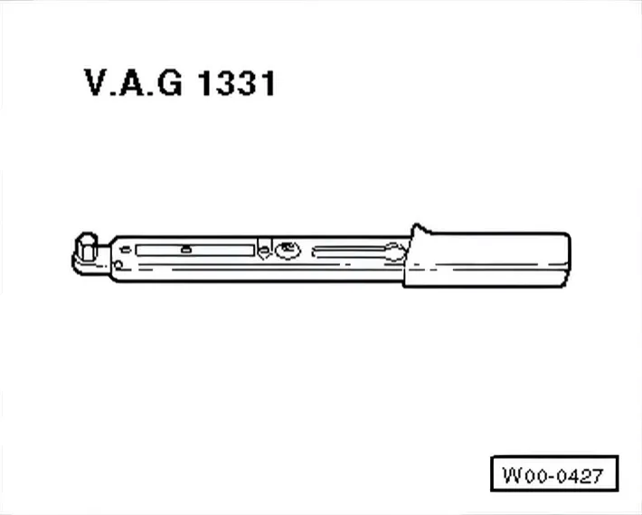
- Torque wrench - V.A.G 1331-
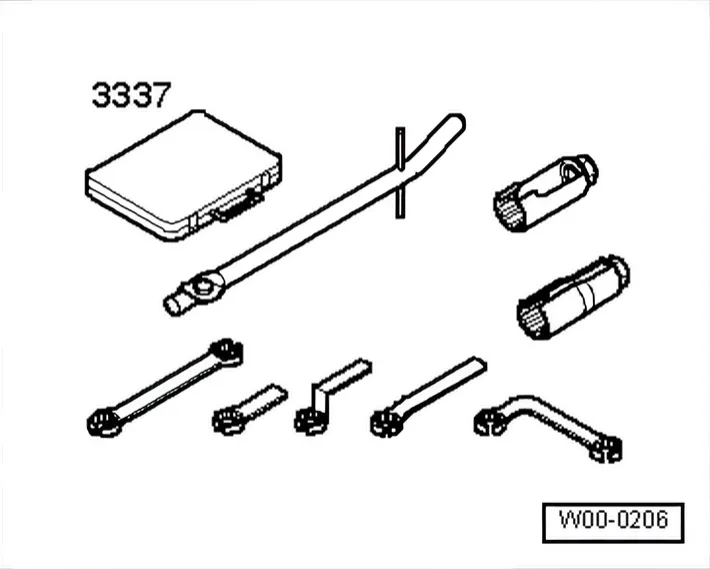
- Lambda probe open ring spanner set - 3337-
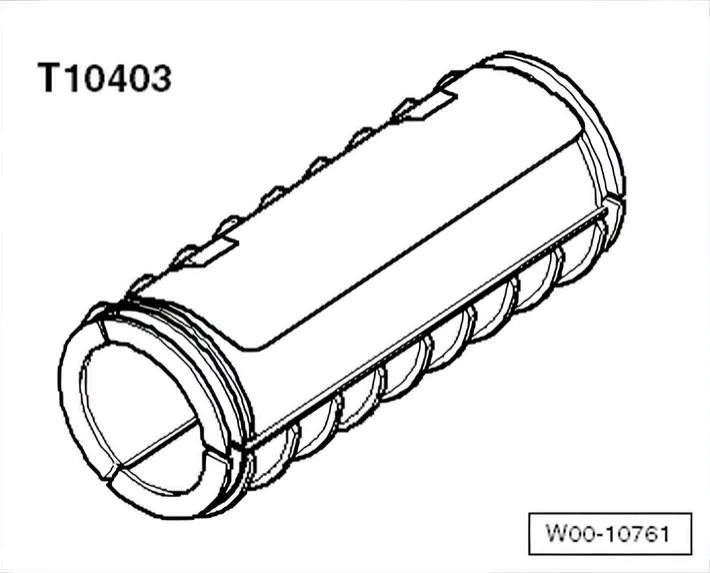
- Transport lock - T10403-
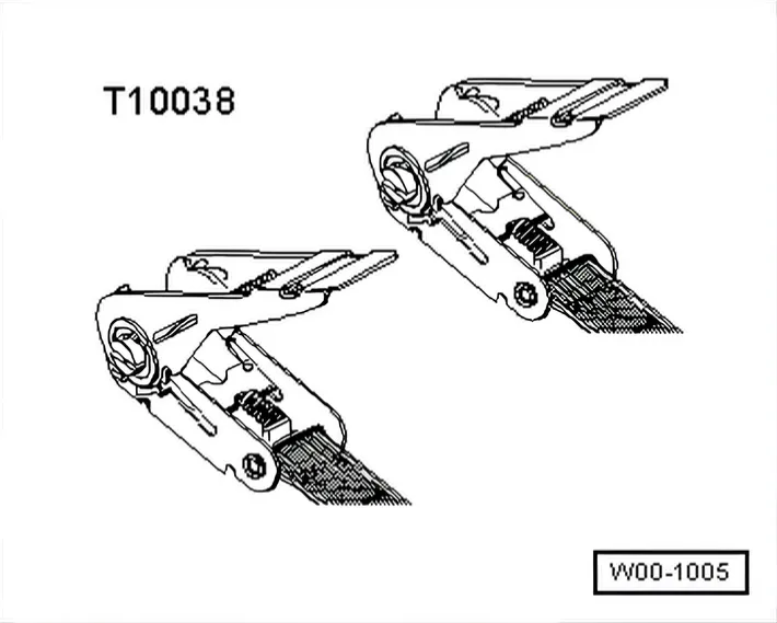
- Tensioning strap - T00038-
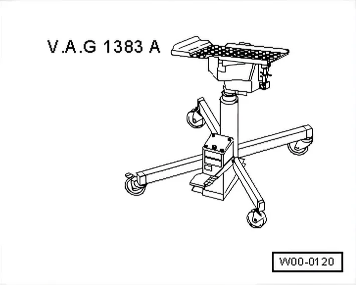
- Engine and gearbox jack - VAG 1383A-
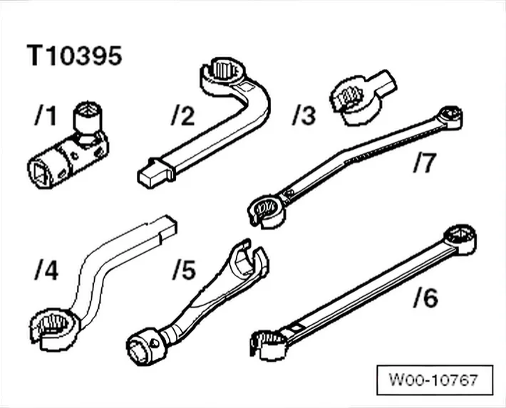
- Tool set - T10395-
- Turn wheels to straight-ahead position.
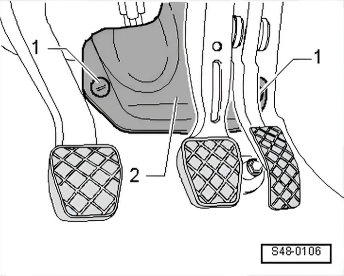
- Remove cover -2- and unscrew plastic nuts -1-.
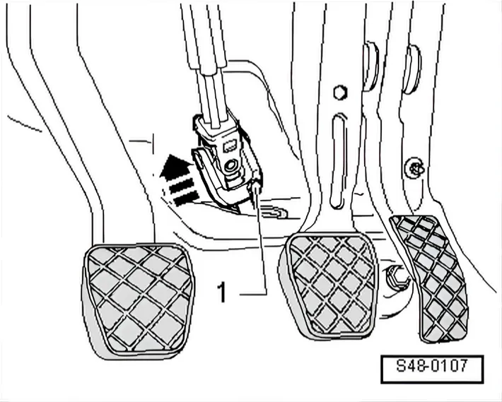
- Unscrew bolt -1- from universal joint and pull universal joint off in direction of arrow.
- Remove engine cover panel ⇒ 3 Engine cover panel.
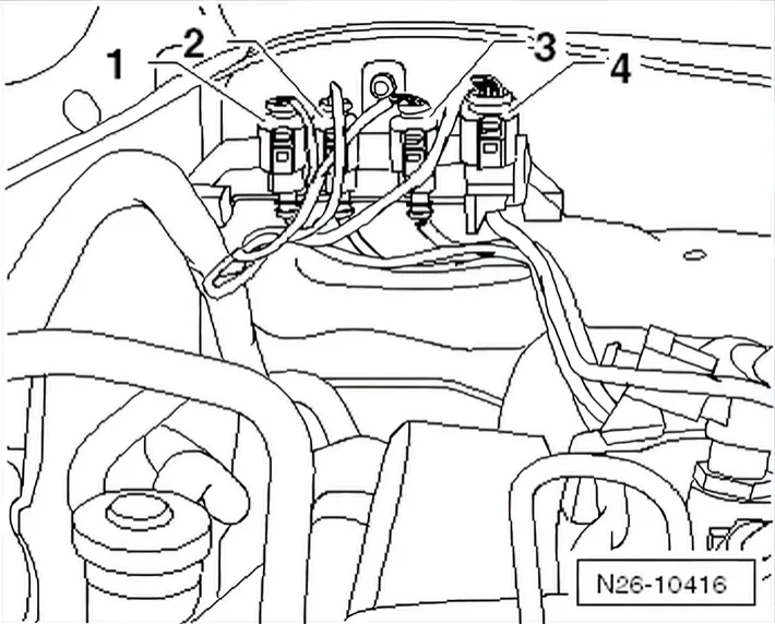
- -1- Separate exhaust gas temperature sender 1 - G 235- connector
- -2- Separate exhaust gas temperature sender 3 - G 495- connector
- -3- Separate exhaust gas temperature sender 4 - G 648- connector
- -4- Separate Lambda probe - G 39- connector
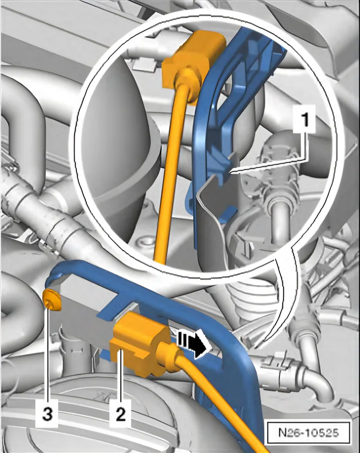
- Separate connector to pressure differential sender - G 505- -2-.
- Unscrew pressure differential sender - G 505- ⇒ Item 2 (2.1.3 Assembly overview - front exhaust pipe with particulate filter, Polo, left-hand drive).
- Pull lines out of retainers on engine and remove heat shield from particulate filter; if necessary remove cable ties.
- Unscrew Lambda probe - G 39- using Lambda probe open ring spanner set - 3337- ⇒ Item 6 (2.1.3 Assembly overview - front exhaust pipe with particulate filter, Polo, left-hand drive).
- Unscrew exhaust temperature sender 3 -G 495- using wrench - T10395/6- ⇒ Item 15 (2.1.3 Assembly overview - front exhaust pipe with particulate filter, Polo, left-hand drive).
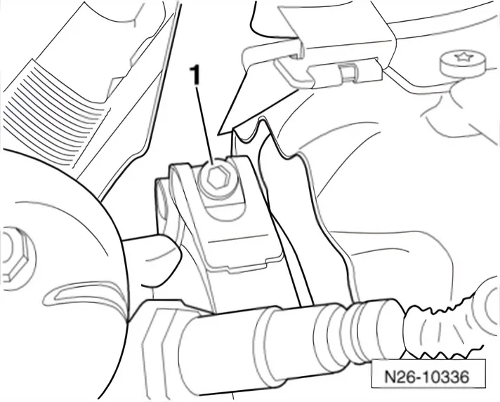
- Remove securing clamp -1- between particulate filter and turbocharger.
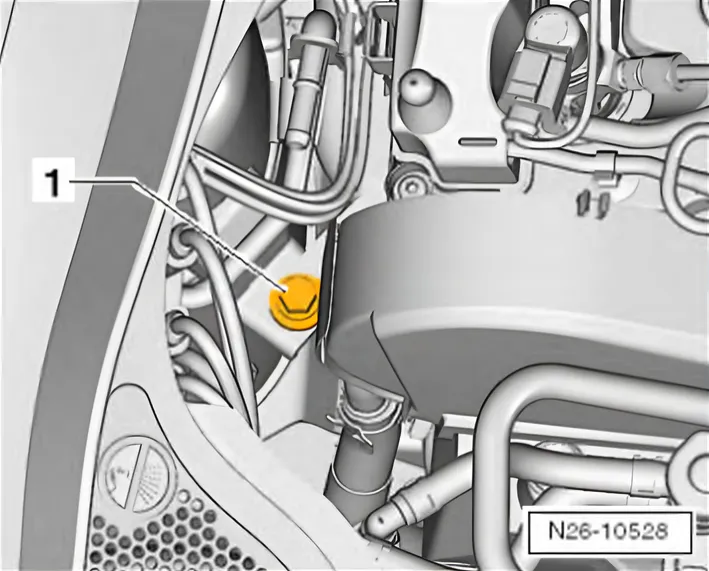
- Unscrew bolt -1-.
- Remove noise insulation:
Polo ⇒ General body repairs, exterior; Rep. gr. 50; Noise insulation; Assembly overview - noise insulation
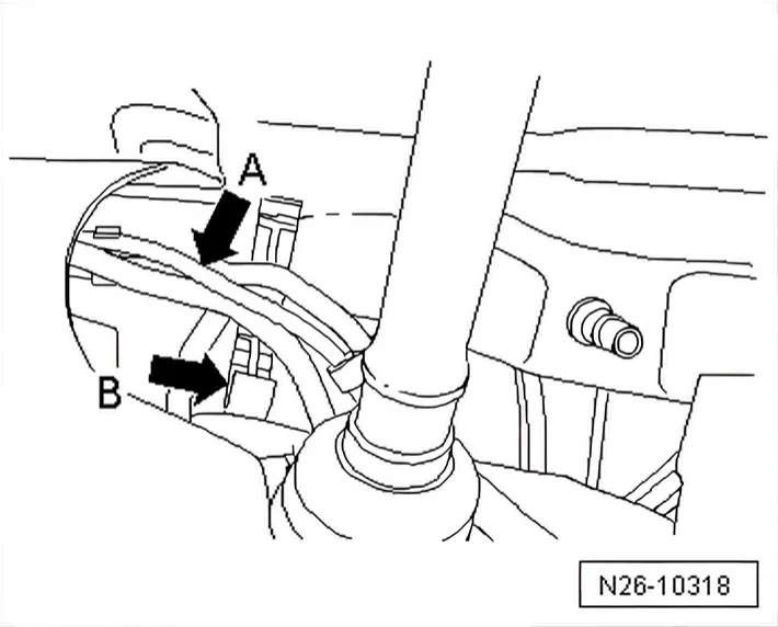
- Open bracket -B- of hydraulic lines -A-.
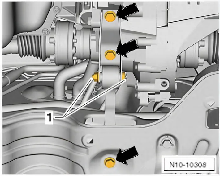
- Remove pendulum support -arrows-.
Do not loosen item -1-.
- Place engine and gearbox jack engine and gearbox jack - VAG 1383A- below subframe.
- Fix subframe in position ⇒ Running gear, axles, steering; Rep. gr. 40; Subframe; Fixing subframe in position.
- Loosen anti-roll bar from top of coupling rod ⇒ Running gear, axles, steering; Rep. gr. 40; Subframe; Removing and installing anti-roll bar.
- Lower subframe with engine and gearbox jack - VAG 1383A-; steering remains on subframe.
Do not open the hydraulic steering circuit for this.
- Lower on the right side max. 10 cm -movement arrow-.
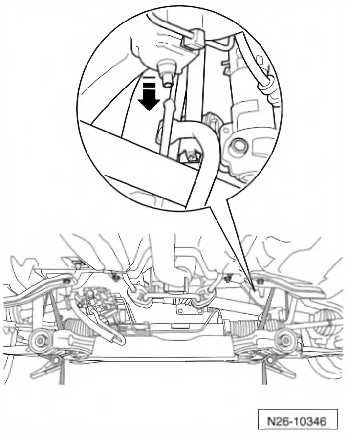
- To prevent the hydraulic lines being overstretched, lower on the left side max. 7 cm -movement arrow-.
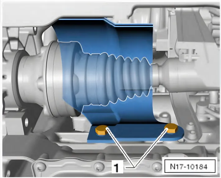
- Remove securing bolts -1- and remove cover from cylinder block for right drive shaft.
- Disregard -item 2-.
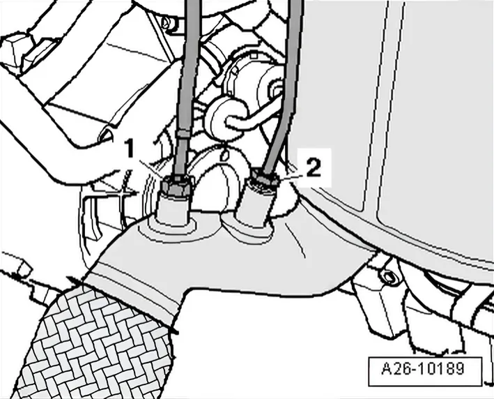
- Unscrew exhaust gas temperature sender 4 - G 648- -item 1- from exhaust pipe downstream of particulate filter.
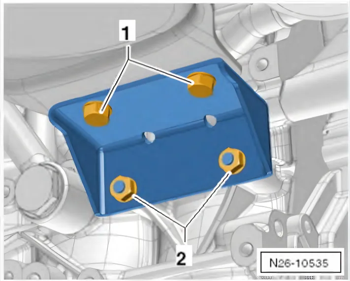
- Unscrew bolts -1- and then nuts -2-.
- Remove particulate filter bracket.
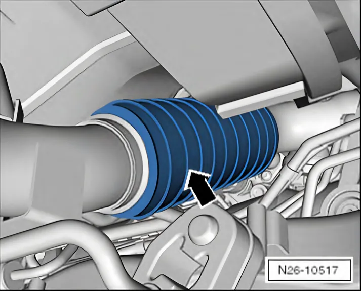
If particulate filter is to be re-installed, a transportation lock - T10403- -arrow- must always be secured to flexible joint in front exhaust pipe.
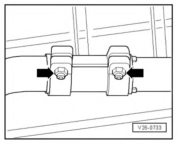
- Loosen securing bolts -arrows- of clamping sleeve, then push down backwards from front exhaust pipe.
- Detach front exhaust pipe from mounting brackets.
Carefully remove front exhaust pipe with particulate filter together with pressure differential sender - G 505- above lowered subframe.
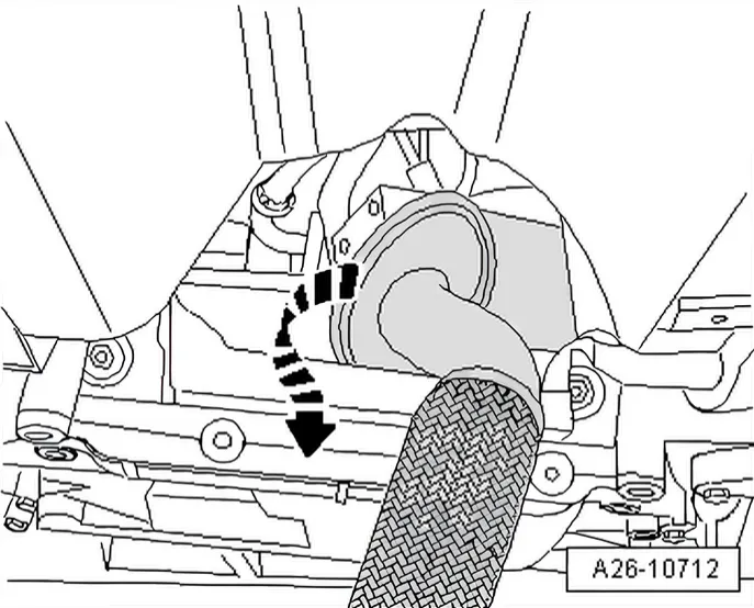
- Remove particulate filter by turning 180° around its own axis.
Installing
Specified torques ⇒ 2.1.3 Assembly overview - front exhaust pipe with particulate filter, Polo, left-hand drive.
Specified torque for subframe ⇒ Running gear, axles, steering; Rep. gr. 40; Subframe; Assembly overview - subframe.
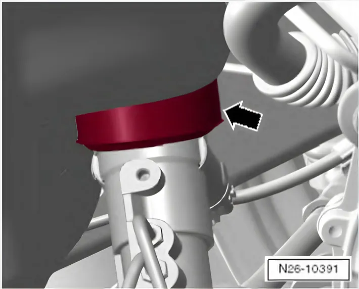
Check fitting position of seal -arrow- (steering donut).
Installation is carried out in the reverse order. When installing, note the following:
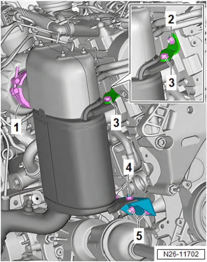
Observe sequence when installing particulate filter:
| 1) | Position particulate filter on turbo charger and loosely attach clip -1- |
|---|---|
| 2) | Screw in bolts and nuts -2 … 5- loosely by hand • It must still be possible to move particulate filter and bracket |
| 3) | Tighten clip -1- |
| 4) | Tighten nuts and bolts -2- and -5- |
| 5) | Tighten nuts and bolts -3- and -4- |
Specified torque for bolts for drive shaft heat shield -1- ⇒ Running gear, axles, steering; Rep. gr. 40; Drive shaft; Removing and installing drive shaft heat shield.
- Aligning exhaust system free of stress ⇒ 1.2.2 Aligning exhaust system free of stress, Polo.
2.2.3 Removing and installing particulate filter, Polo, right-hand drive
Special tools and workshop equipment required
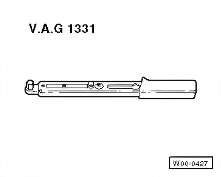
- Torque wrench - V.A.G 1331-
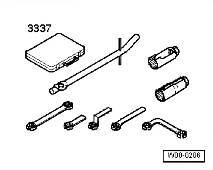
- Lambda probe open ring spanner set - 3337-
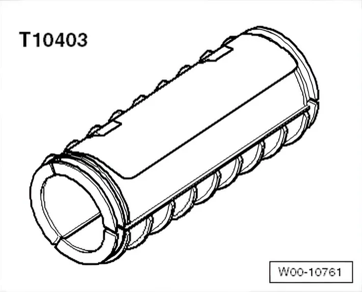
- -T 10403-
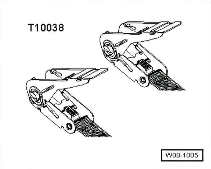
- Tensioning strap - T00038-
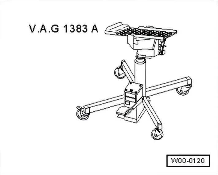
- Engine and gearbox jack - VAG 1383A-
- Tool set - T10395-
Removing
- Turn wheels to straight-ahead position.
- Remove cover -2- and unscrew plastic nuts -1-.
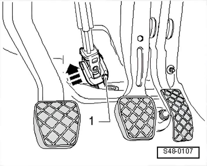
- Unscrew bolt -1- from universal joint and pull universal joint off in direction of arrow.
- Remove engine cover panel ⇒ 3 Engine cover panel.
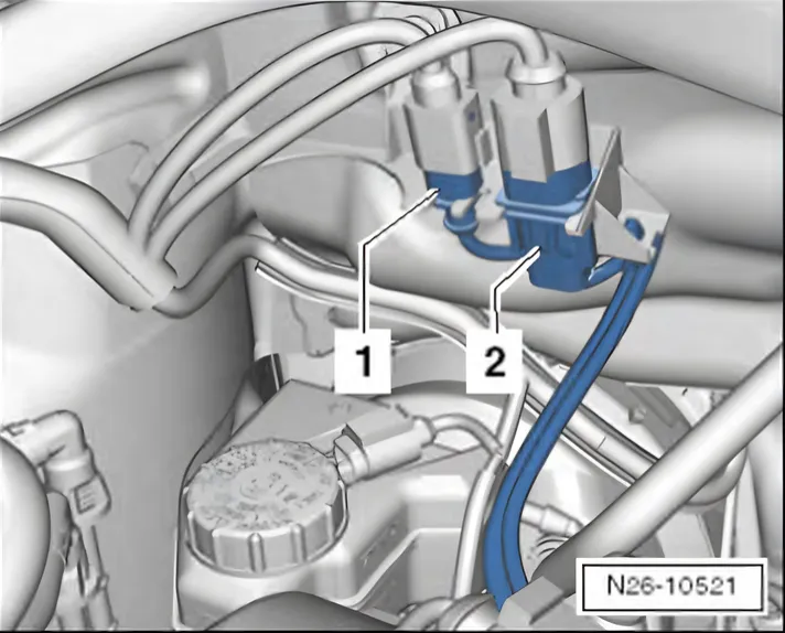
- Disconnect connectors -1- for exhaust temperature sender 1 - G 235-.
- Disconnect connectors -2- for Lambda probe - G 39-.
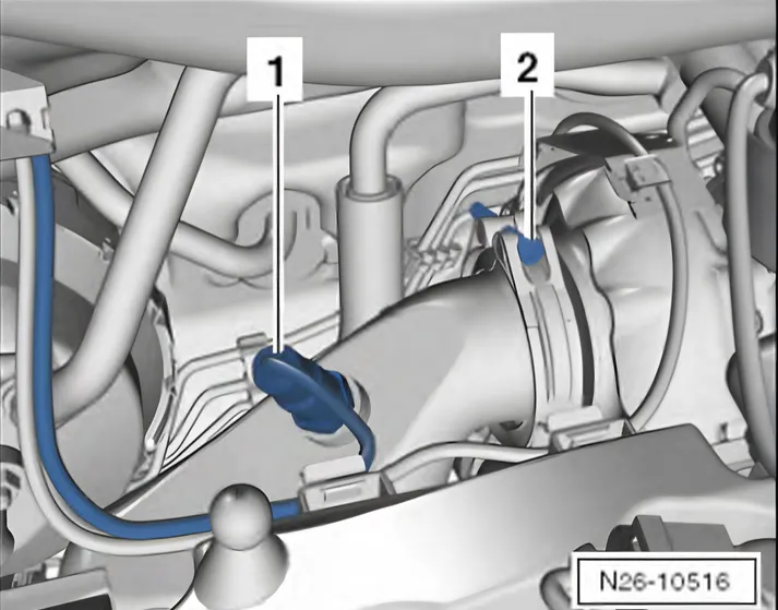
- Unscrew lambda probe - G 39- -1- using lambda probe open ring spanner set - 3337-.
- Remove securing clamp -2- between particulate filter and turbocharger.
- Remove noise insulation:
Polo ⇒ General body repairs, exterior; Rep. gr. 50; Noise insulation; Assembly overview - noise insulation
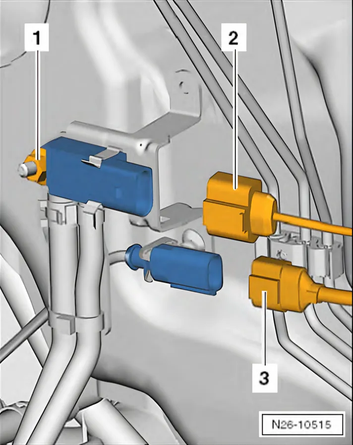
- Separate connector -2- to pressure differential sender - G 505-.
- Unscrew pressure differential sender - G 505- -1-.
- Separate connector -3- to pressure differential sender - G 505-.
- Pull lines from retainers and remove cable ties if necessary.
Do not bend the flexible joint in the front exhaust pipe by more than 10° because it might otherwise be damaged.
If particulate filter is to be re-installed, a transportation lock - T10403- -arrow- must always be secured to flexible joint in front exhaust pipe.
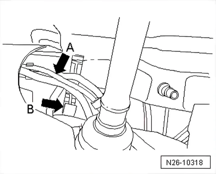
- Open bracket -B- of hydraulic lines -A-.
- Remove pendulum support -arrows-.
Do not loosen item -1-.
- Place engine and gearbox jack - VAG 1383A- under subframe.
- Fix subframe in position ⇒ Running gear, axles, steering; Rep. gr. 40; Subframe; Fixing subframe in position.
- Loosen anti-roll bar from top of coupling rod ⇒ Running gear, axles, steering; Rep. gr. 40; Subframe; Removing and installing anti-roll bar.
- Lower subframe with engine and gearbox jack - VAG 1383A-; steering remains on subframe.
Do not open the hydraulic steering circuit for this.
- Lower on the right side max. 10 cm -movement arrow-.
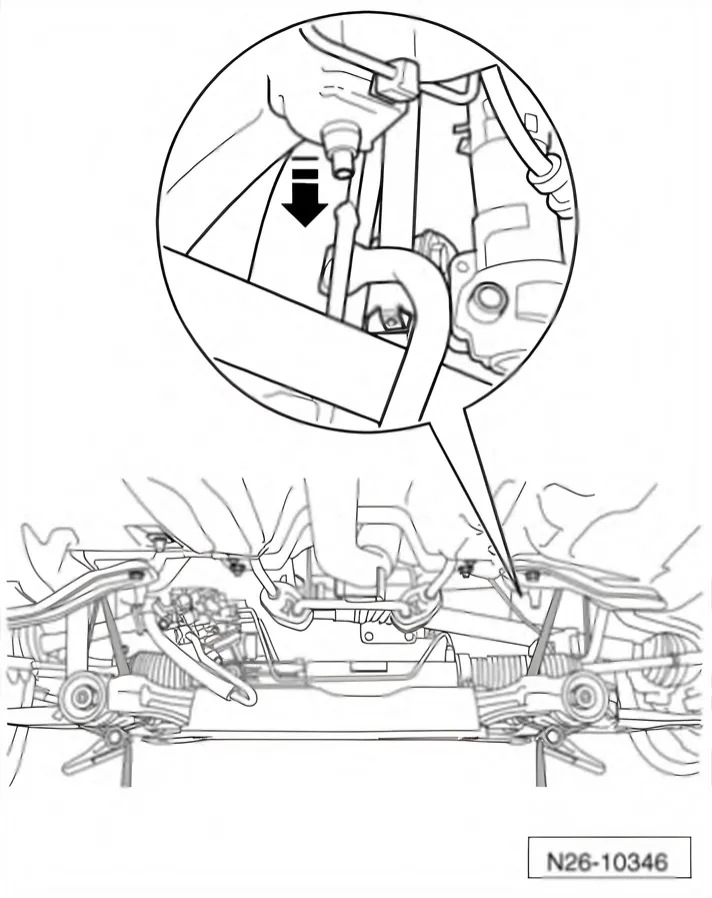
- To prevent the hydraulic lines being overstretched, lower on the left side max. 7 cm.
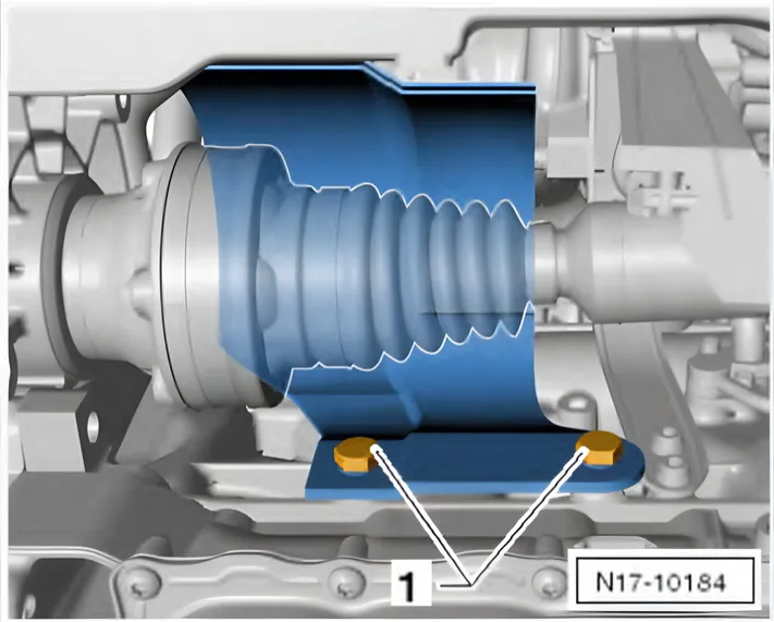
- Remove securing bolts -1- and remove cover from cylinder block for right drive shaft.
- Unscrew exhaust gas temperature sender 3 - G 495- using - T10395/6- ⇒ Item 5 (2.1.4 Assembly overview - front exhaust pipe with particulate filter, Polo, right-hand drive) from front exhaust pipe.
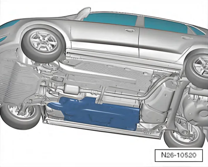
- Remove right underbody panel.
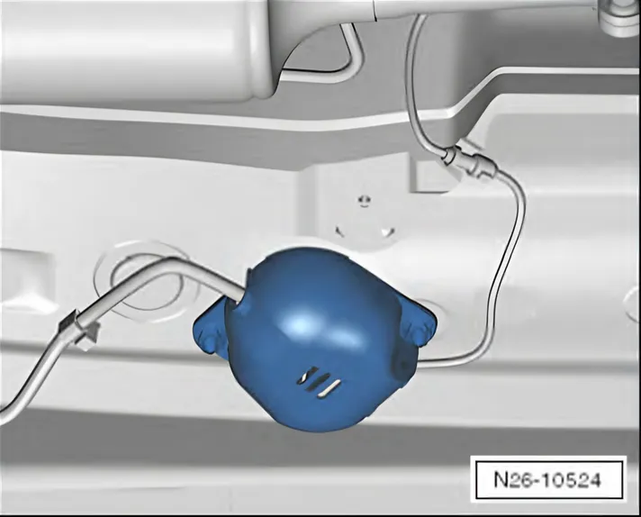
- Remove cover from connector for exhaust temperature sender
- 4 G 648-.
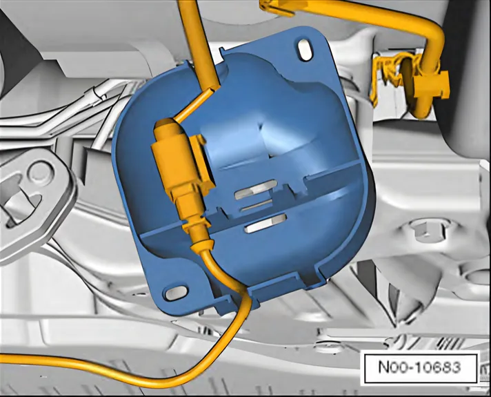
- Disconnect connector for exhaust temperature sender 4 - G 648-.
- Unscrew bolts -1- and then nuts -2-.
- Remove particulate filter bracket.
If particulate filter is to be re-installed, a transportation lock - T10403- -arrow- must always be secured to flexible joint in front exhaust pipe.
- Loosen securing bolts -arrows- of clamping sleeve, then push down backwards from front exhaust pipe.
- Detach front exhaust pipe from mounting brackets.
Carefully remove front exhaust pipe with particulate filter together with pressure differential sender - G 505- above lowered subframe.
- Remove particulate filter by turning 180° around its own axis.
Installing
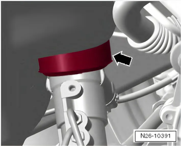
Check fitting position of seal -arrow- (steering donut).
Installation is carried out in the reverse order. When installing, note the following:
- Renew seal ⇒ Item 2 (2.1.4 Assembly overview - front exhaust pipe with particulate filter, Polo, right-hand drive).
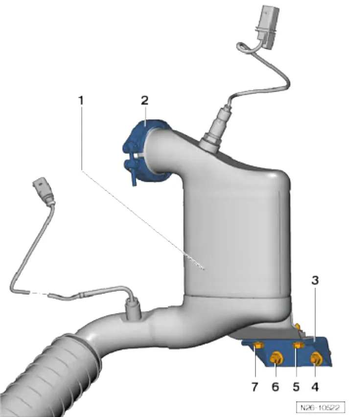
Installation sequence for particulate filter
- 1. Particulate filter mounting -1- on turbocharger, clamp -2- (for positioning only)
- 2. Bracket on cylinder block with nuts -4- + -6- (for positioning only). Bolts -5- + -7- also (for positioning)
- 3. Tighten clamp -2- to turbocharger 7 Nm
- 4) Tighten left nut -6- to crankcase 25 Nm
- 5) Tighten right nut -4- to crankcase 25 Nm
- 6) Tighten left bolt -7- of bracket to diesel particulate filter 25 Nm
- 7) Tighten right bolt -5- of bracket to diesel particulate filter 25 Nm
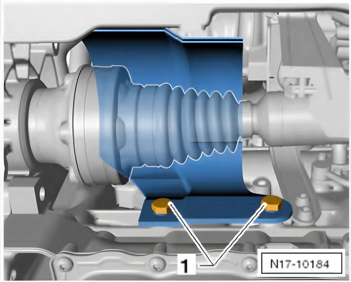
Specified torque for bolts for drive shaft heat shield -1- ⇒ Running gear, axles, steering; Rep. gr. 40; Drive shaft; Removing and installing drive shaft heat shield.
Specified torque for exhaust gas temperature sender ⇒ 3.2 Removing and installing parts of exhaust gas temperature regulation.
- Aligning exhaust system free of stress ⇒ 1.2.2 Aligning exhaust system free of stress, Polo.
Tightening torques on this page
5 torques
2.2.3 Removing and installing particulate filter, Polo, right-hand driveTo the steps ↑
| Step | Torque |
|---|---|
| 3. Tighten clamp -2- to turbocharger 7 Nm | 7 Nm |
| 4) Tighten left nut -6- to crankcase 25 Nm | 25 Nm |
| 5) Tighten right nut -4- to crankcase 25 Nm | 25 Nm |
| 6) Tighten left bolt -7- of bracket to diesel particulate filter 25 Nm | 25 Nm |
| 7) Tighten right bolt -5- of bracket to diesel particulate filter 25 Nm | 25 Nm |