
7-speed DSG gearbox 0AM (DQ200) · Clutch · Dual Clutch, Removing and Installing, through Transmission Production Date 05/2011
“K 1” and “K 2” Clutch Engaging Bearing Position, Adjusting, Transmission Production Date through 05/2011
Special tools and workshop equipment required
- Setting Tool - Release Bearing - T10374-
- Ruler (2 pc.) - T40100-
- Digital Depth Gauge - 300mm for example -VAS6594-
- Adhesive - AMV 195 KD1 01-
- Micrometer
When replacing the dual clutch and its components, the “K 1 and K 2” engaging bearing position must always be readjusted.
Brief Description
- The position of the engaging bearing is comparable to clutch play on a manual transmission. There are tolerances in the 7-speed DSG® transmission 0AM engaging system and in the transmission itself. There are also tolerances within the dual clutch. These tolerances must be taken into account separately when performing the adjustments.
- The following procedure describes how all necessary measurements are determined from the transmission side in order to select the correct shim. In addition to this, the tolerances in the clutch already determined by the manufacturer. The transmission side tolerances and the tolerances in the clutch determine the thickness of the shim.
- Follow the work sequence.
Overview - Clutch Mechanism
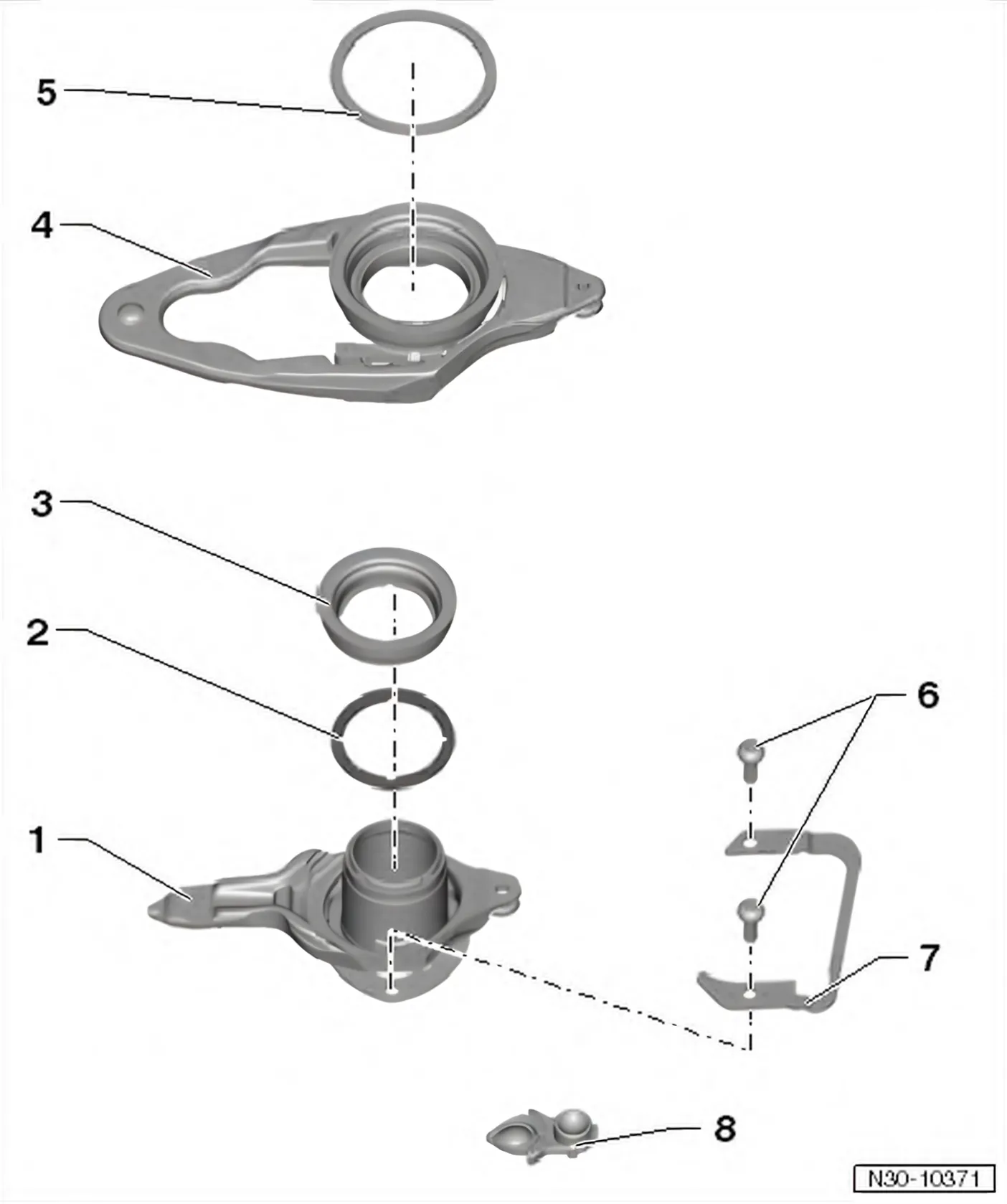
- 1 Small Engaging Lever for »K 2«
- Always replace when replacing the dual clutch
- 2 Shim for »K 2«
- 3 Engaging Bearing for »K 2«
- Always replace when replacing the dual clutch
- 4 Large Engaging Lever for “K 1”
- With large engaging bearing
- Always replace when replacing the dual clutch
- 5 Shim for “K 1”
- 6 Bolts
- 8 Nm +90°
- Always replace after removing
- 7 Bracket
- Not equipped in some older transmissions
- Always replace when replacing the dual clutch
- 8 Support
- Always replace when replacing the dual clutch
Requirement:
- The transmission flange must be even so that it has a good surface for the ruler.
- DSG Transmission Mechatronic - J743- must be installed.
- Tightening specifications. Refer to ⇒ 1.1 Overview - Dual Clutch, through Transmission Production Date 05/2011.
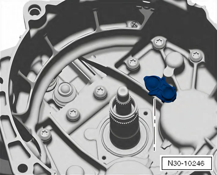
Step 1: Prepare to Measure the Dual Clutch
- Insert the engaging lever mount.
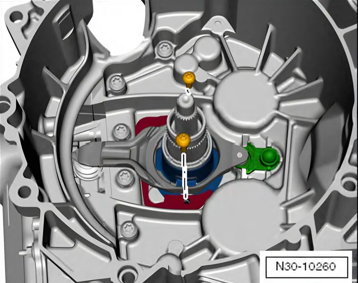
- Install the small engaging lever with the bracket and tighten with two new screws.
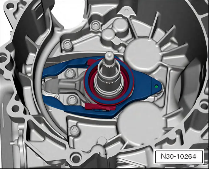
- Install the large engaging lever.
- Make sure both engaging levers fit correctly.
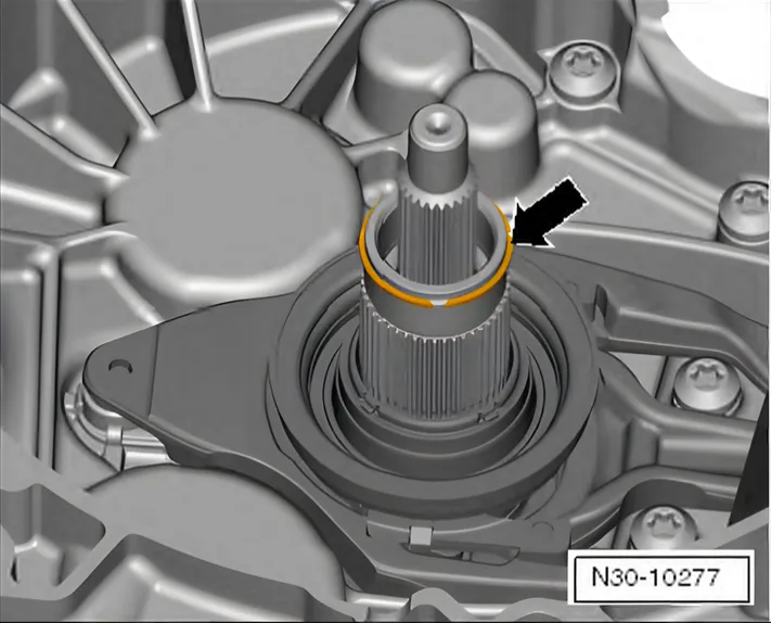
- Install the old circlip -arrow- for the outer input shaft.
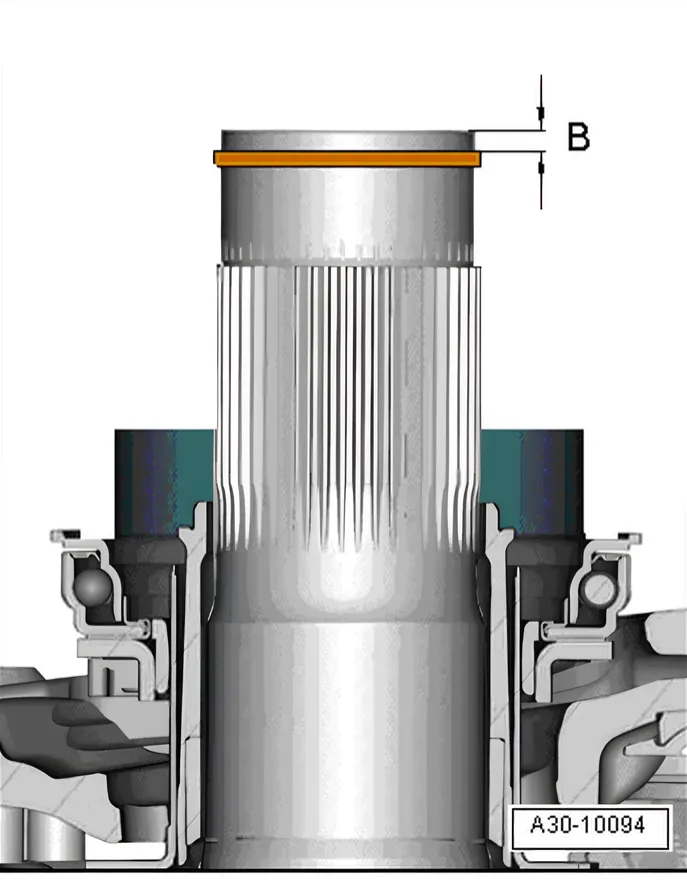
Step 2: Determine the Dimension “B” for Clutch “K 1” and “K 2”.
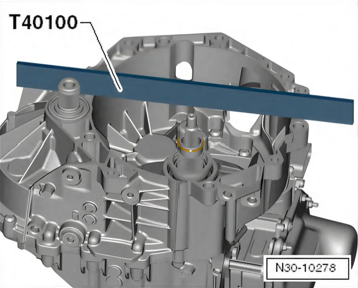
- Place Ruler (2 pc.) - T40100- across the end of the shaft on the transmission flange.
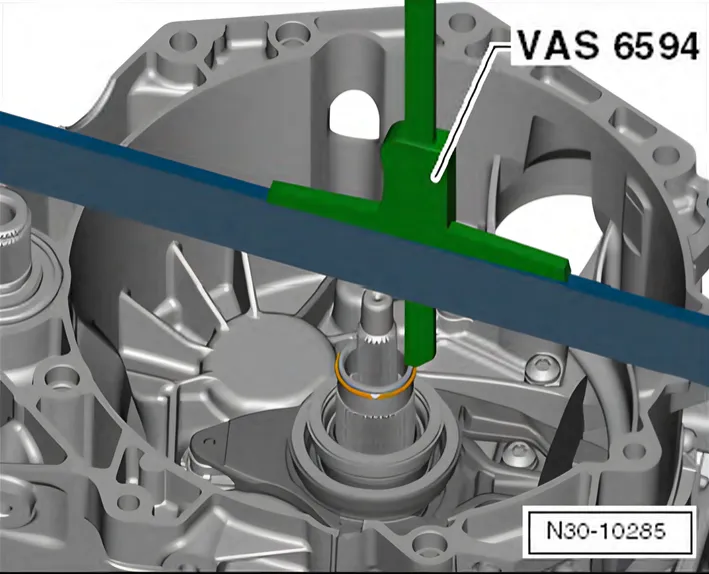
- Place the Digital Depth Gauge - 300mm - VAS6594- on top of the Ruler (2 pc.) - T40100- and position the depth slide on the outer input shaft.
- Set the Depth Gauge to “0”.
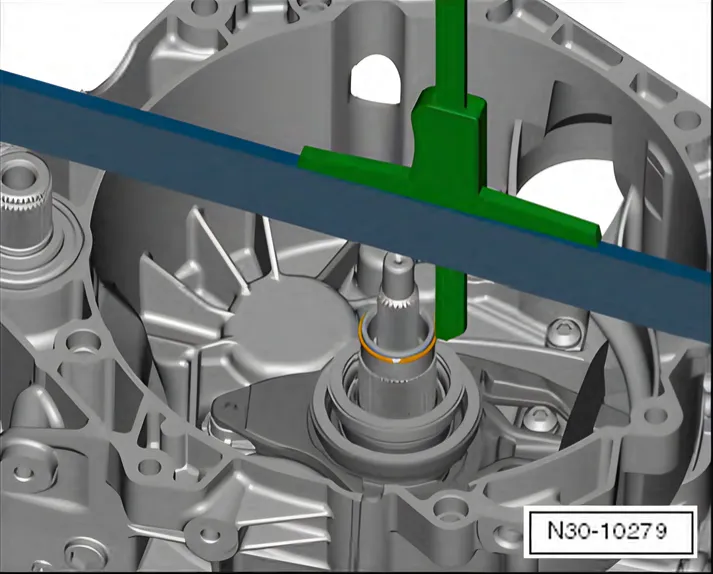
- Position the depth slide on the locking ring, as illustrated.
- Measure dimension “B1 ” on the locking ring in this position.
- Example: dimension “B1 ” = 2.92 mm
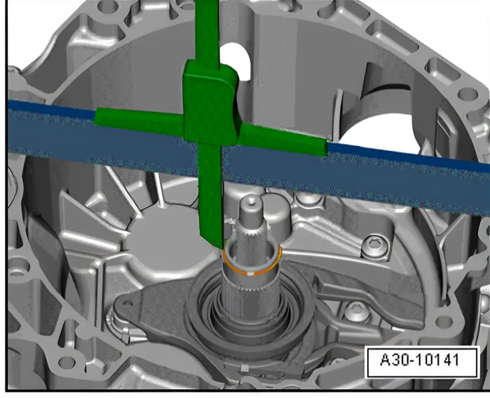
- Measure dimension “B2 ” on the opposite side of the locking ring.
- Calculate the mean value from “B1 ” and “B2 ”.
Formula: (B1 + B2) / 2
Example:
- (2.92 + 3.00) / 2 = 2.96 mm
- Result: dimension “B” = 2.96 mm
- Remove the circlip again and dispose it.
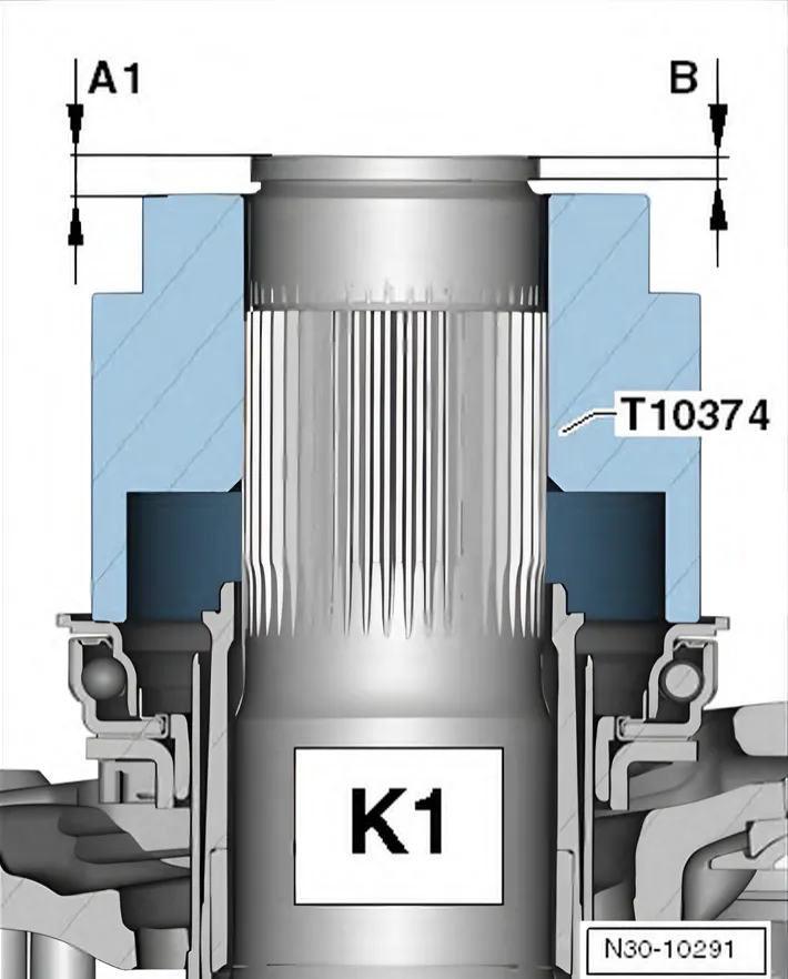
Step 3: Determine the Dimension “A 1” for the “K 1” Clutch Engaging Bearing.
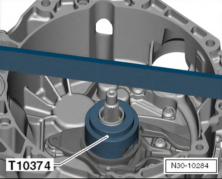
- Place the Setting Tool - Release Bearing - T10374- with the large opening downward on the larger engaging bearing.
- Press and turn the Setting Tool - Release Bearing - T10374- to make sure the Setting Tool - Release Bearing sits correctly on the engaging bearing.
- The engaging bearing turns with the Setting Tool - Release Bearing - T10374-.
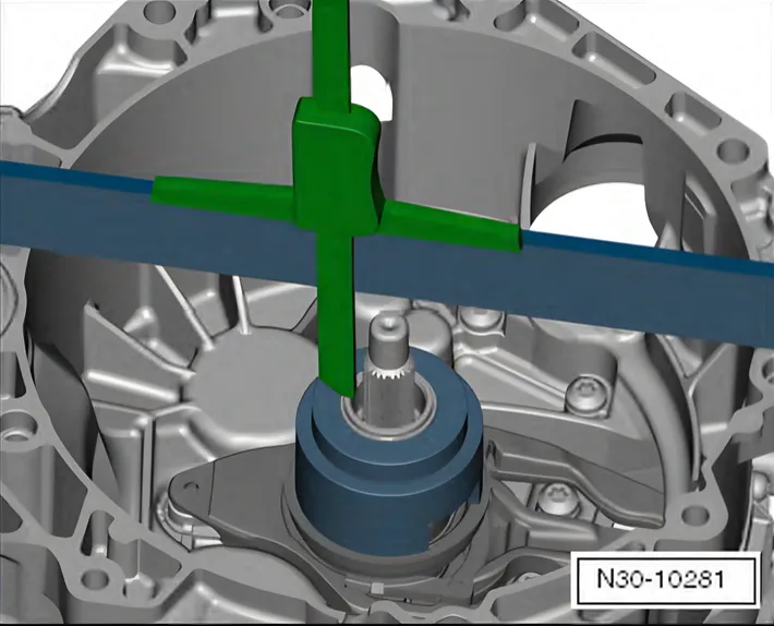
- Place the Digital Depth Gauge - 300mm - VAS6594- on top of the Ruler (2 pc.) - T40100- and position the depth slide on the outer input shaft.
- The Ruler (2 pc.) - T40100- lies straight across the transmission flange over the end of the shaft.
- Set the Depth Gauge to “0”.
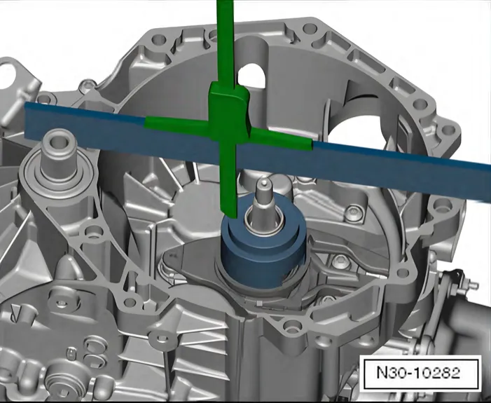
- Position the depth gauge on the Setting Tool - Release Bearing - T10374- as shown.
- Measure dimension “A 1a ” at this position on the Setting Tool - Release Bearing - T10374-.
- Example: dimension “A 1a ” = 2.61 mm
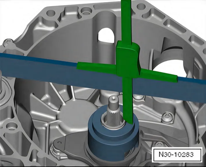
- On the opposite side, measure the dimension “A 1b ” on the Setting Tool - Release Bearing - T10374-.
- Example: dimension “A 1b ” = 2.81 mm
- Calculate the average value from dimension “A 1a ” and “A 1b ”.
Formula: (A 1a + A1b) / 2
Example:
- (2.61 + 2.81) / 2 = 2.71 mm
- Result: dimension “A 1” = 2.71 mm
Step 4: Measuring the Installation Depth for the “K 1” Clutch Engaging Bearing.
| Dimension “A 1” | |
|---|---|
| – | Dimension “B” |
| + | Outer Setting Tool - Release Bearing - T10374- height (51.81 mm; fixed value) |
| = | Actual value of the “K 1” clutch engaging bearing installation depth |
Example:
- 2.71 mm – 2.96 mm + 51.81 mm = 51.56 mm
- Result: installation depth for “K 1” clutch engaging bearing = 51.56 mm
Step 5: Measure the Air Gap for “K 1” Clutch.
| Engaging bearing installation depth actual value | |
|---|---|
| – | Engaging bearing installation depth specified value (50.08 mm; fixed value) |
| = | Air gap for “K 1” clutch |
Example:
- 51.56 mm – 50.08 mm = 1.48 mm
- Result: “K 1” clutch air gap = 1.48 mm
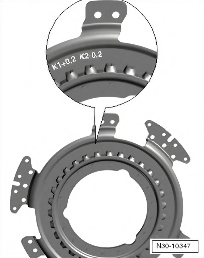
Step 6: Measure the Clutch Tolerance for “K 1” Clutch.
- Read the clutch tolerance value on the new clutch.
- Example: clutch tolerance read on the clutch “K 1 = +0.2”, as illustrated.
Step 7: Measure the “SK 1” Shim Thickness.
| Air gap for “K 1” clutch | |
|---|---|
| –/+ | Clutch tolerance for clutch “K 1” |
| = | Calculated thickness for shim “SK 1” |
Example:
- 1.48 mm + 0.20 mm = 1.68 mm
- Result: calculated “SK 1” shim thickness = 1.68 mm
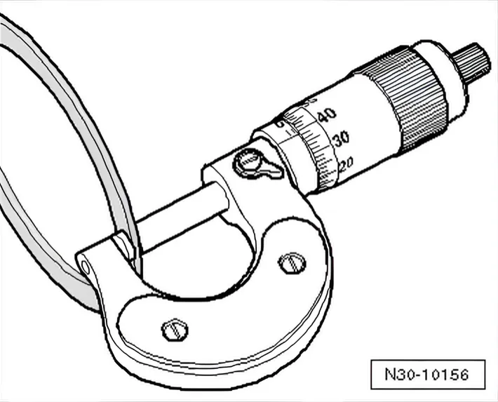
- Measure the needed shim from the shims supplied and keep it close for installation.
| Calculated Shim Thickness mm | Available Shim Thicknesses in mm |
|---|---|
| 0.31 to 0.90 | 0.80 |
| 0.91 to 1.10 | 1.00 |
| 1.11 to 1.30 | 1.20 |
| 1.31 to 1.50 | 1.40 |
| 1.51 to 1.70 | 1.60 |
| 1.71 to 1.90 | 1.80 |
| 1.91 to 2.10 | 2.00 |
| 2.11 to 2.30 | 2.20 |
| 2.31 to 2.50 | 2.40 |
| 2.51 to 2.70 | 2.60 |
| 2.71 to 3.30 | 2.80 |
Example:
- Result: calculated “SK 1” shim thickness = 1.68 mm
- Selected shim thickness = 1.60 mm
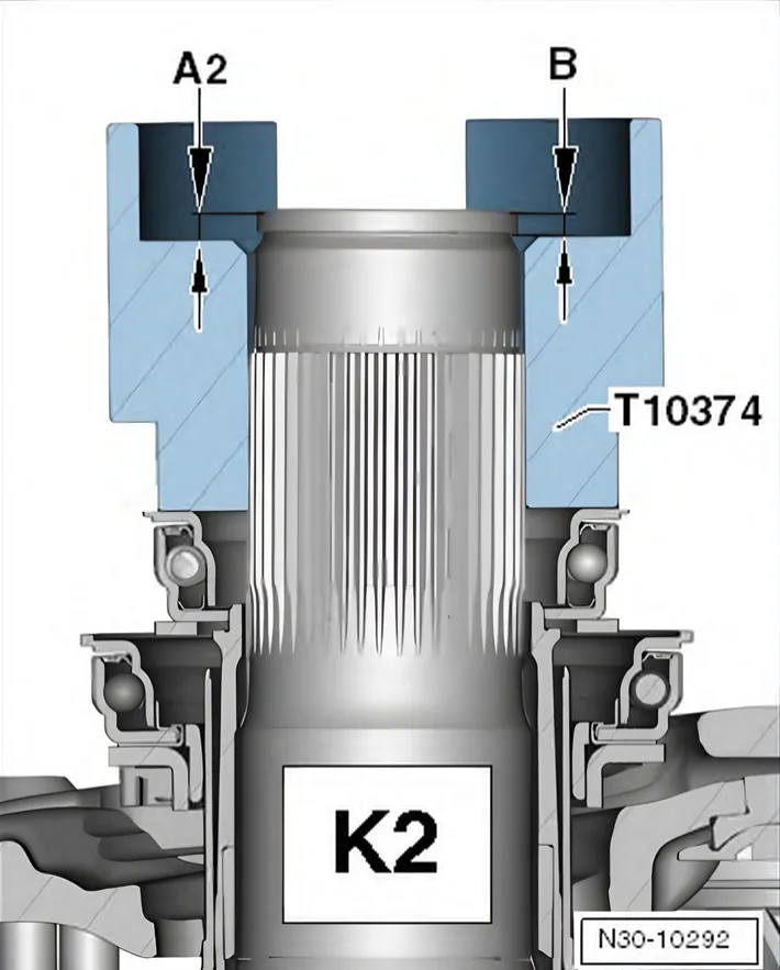
Step 8: Determine Dimension “A 2” for “K 2” Clutch Engaging Bearing
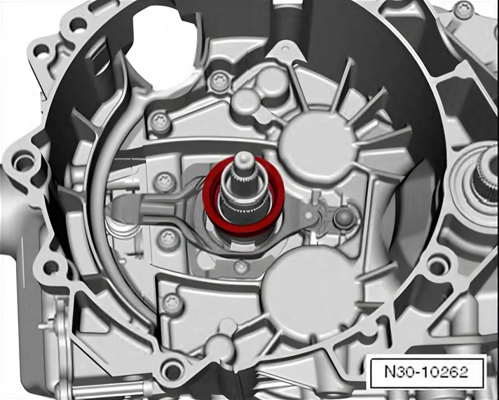
- Only insert the small engaging bearing.
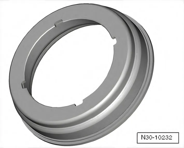
- The small engaging bearing fits in only one position due to the 4 grooves.
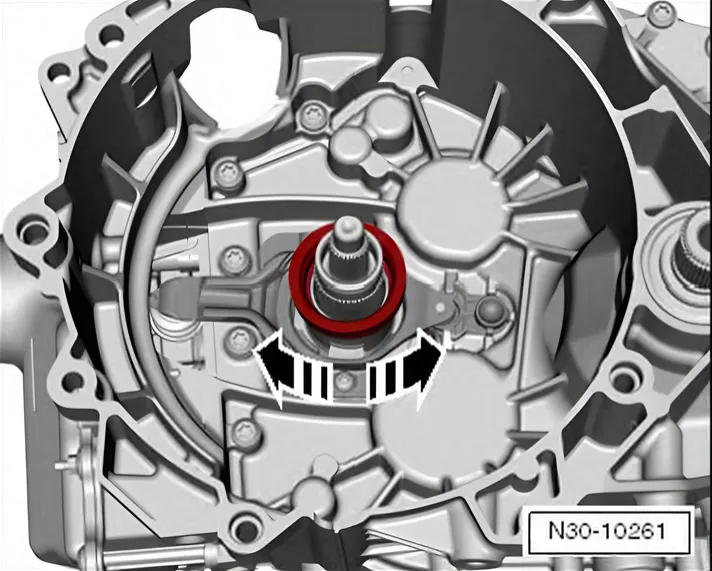
- Turn the engaging bearing in direction of -arrows- to make sure it is installed correctly and fits correctly in the grooves.
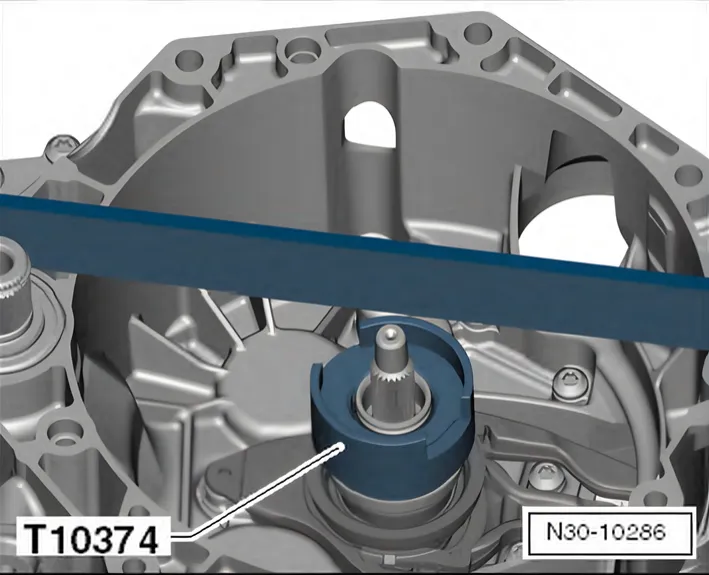
- Place the Setting Tool - Release Bearing - T10374- with the large opening upward on the small engaging bearing.
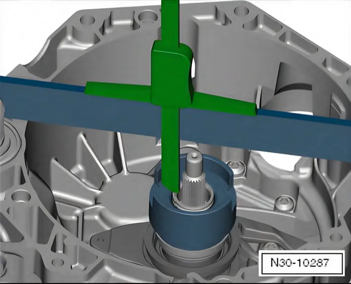
- Place the Digital Depth Gauge - 300mm - VAS6594- on top of the Ruler (2 pc.) - T40100- and position the depth slide on the outer input shaft.
- The Ruler (2 pc.) - T40100- lies straight across the transmission flange over the end of the shaft.
- Set the Depth Gauge to “0”.
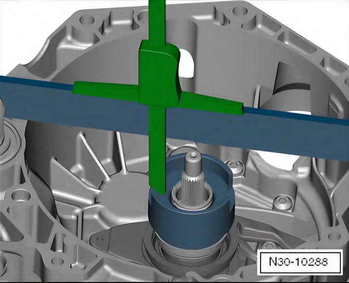
- Position the depth gauge on the Setting Tool - Release Bearing - T10374- as shown.
- Measure dimension “A 2a ” at this position on the Setting Tool - Release Bearing - T10374-.
- Example: dimension “A 2a ” = 2.50 mm
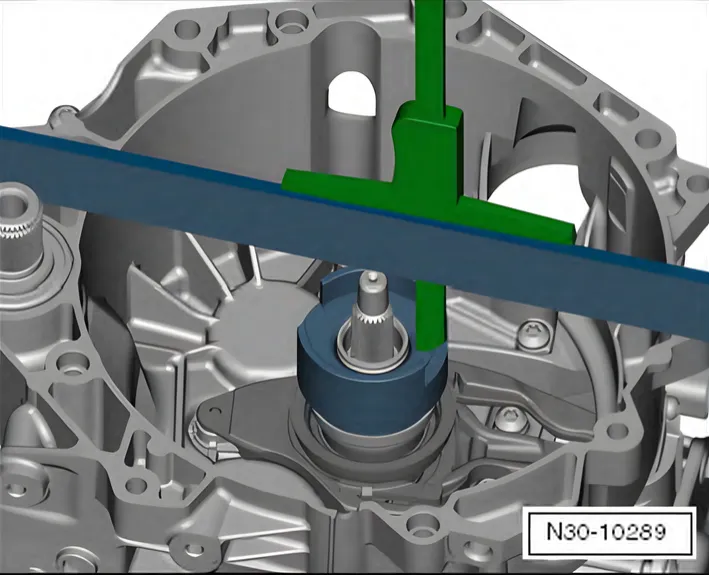
- On the opposite side, measure the dimension “A 2b ” on the Setting Tool - Release Bearing - T10374-.
- Example: dimension “A 2b ” = 2.54 mm
- Calculate the average value from dimension “A 2a ” and “A 2b ”.
Formula: (A 2a + A 2b) / 2
Example:
- (2.50 + 2.54) / 2 = 2.52 mm
- Result: dimension “A 2” = 2.52 mm
Step 9: Measure the Installation Depth for the “K 2” Clutch Engaging Bearing.
| Dimension “A 2” | |
|---|---|
| – | Dimension “B” |
| + | Inner Setting Tool - Release Bearing - T10374- dimension (36.20 mm; fixed value) |
| = | Actual value of the “K 2” clutch engaging bearing installation depth |
Example:
- 2.52 mm – 2.96 mm + 36.20 mm = 35.76 mm
- Result: Actual value for “K 2” clutch engaging bearing installation depth = 35.76 mm
Step 10: Measure the Air Gap for “K 2” Clutch.
| Engaging bearing installation depth actual value | |
|---|---|
| – | Specified value for engaging bearing installation depth (34.35 mm; fixed value) |
| = | Air gap for “K 2” clutch |
Example:
- 35.76 mm – 34.35 mm = 1.41 mm
- Result: Air gap for “K 2” clutch = 1.41 mm
Step 11: Measure the Clutch Tolerance for “K 2” Clutch.
- Read the clutch tolerance value on the new clutch.
- Example: clutch tolerance read on the clutch “K 2 = – 0.2”, as illustrated.
Step 12: Measure the “SK 2” Shim Thickness.
| Air gap for “K 2” clutch | |
|---|---|
| –/+ | Clutch tolerance for the clutch “K 2” |
| = | Calculated thickness for shim “SK 2” |
Example:
- 1.41 mm – 0.20 mm = 1.21 mm
- Result: calculated “SK 2” shim thickness = 1.21 mm
- Measure the needed shim from the shims supplied and keep it close for installation.
| Calculated Shim Thickness mm | Available Shim Thicknesses in mm |
|---|---|
| 0.31 to 0.90 | 0.80 |
| 0.91 to 1.10 | 1.00 |
| 1.11 to 1.30 | 1.20 |
| 1.31 to 1.50 | 1.40 |
| 1.51 to 1.70 | 1.60 |
| 1.71 to 1.90 | 1.80 |
| 1.91 to 2.10 | 2.00 |
| 2.11 to 2.30 | 2.20 |
| 2.31 to 2.50 | 2.40 |
| 2.51 to 2.70 | 2.60 |
| 2.71 to 3.30 | 2.80 |
Example:
- Result: calculated “SK 2” shim thickness = 1.21 mm
- Selected shim thickness = 1.20 mm
- Install the dual clutch. Refer to ⇒ 1.4 Dual Clutch, Installing, Transmission Production Date through 05/2011.
Tightening torques on this page
1 torque
| Item | Part | Torque | Notes |
|---|---|---|---|
| 6 | Bolts | 8 Nm +90° | Always replace after removing |