
7-speed DSG gearbox 0AM (DQ200) · Clutch · Dual Clutch, Removing and Installing, from Transmission Production Date 06/2011
Dual Clutch, Removing, Transmission Production Date from 06/2011
Special tools and workshop equipment required
- T-Handle Hook - 3438-
- Engine Bung Set - VAS6122-
- Support Bridge - T10323-
- -T10356/5- from the Subframe Bushing Assembly Tool Kit - T10356-
- Puller - Clutch - T10373-
- Clutch Press Piece - T10376-
Requirement
- The transmission is removed and mounted to the engine/transmission holder. Refer to ⇒ 6 Transmission, Transporting and Securing To Assembly Stand.
- The DSG Transmission Mechatronic - J743- is installed in the transmission.
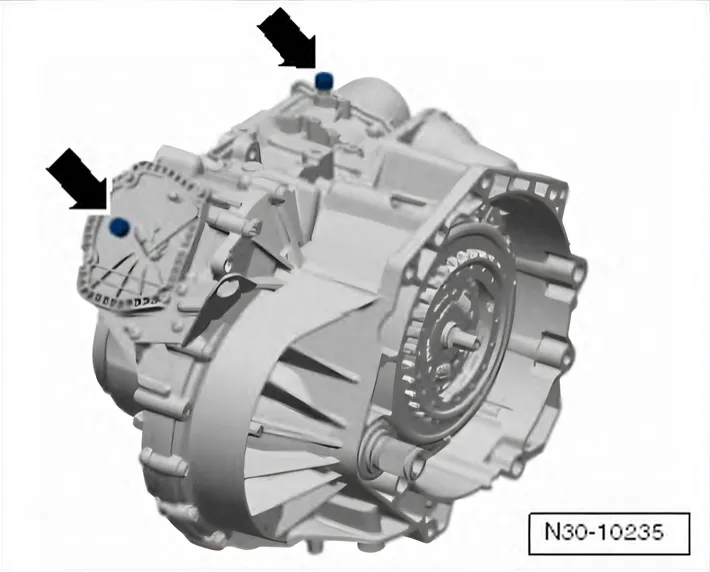
- Remove both breather caps -arrows- and seal with clean oiltight plugs from the Engine Bung Set - VAS6122- for example.
Checking the hydraulic fluid level for the Mechatronic is not possible. The Mechatronic vent must be sealed oil-tight before performing any assembly work.
Fluid that has leaked out of the Mechatronic hydraulic area may not be refilled or checked. Replace the Mechatronic if fluid is leaking.
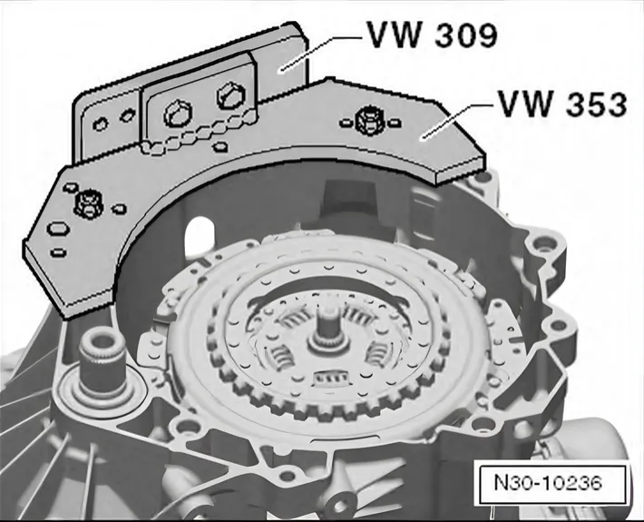
- Turn the transmission on the engine/transmission holder with the clutch facing up.
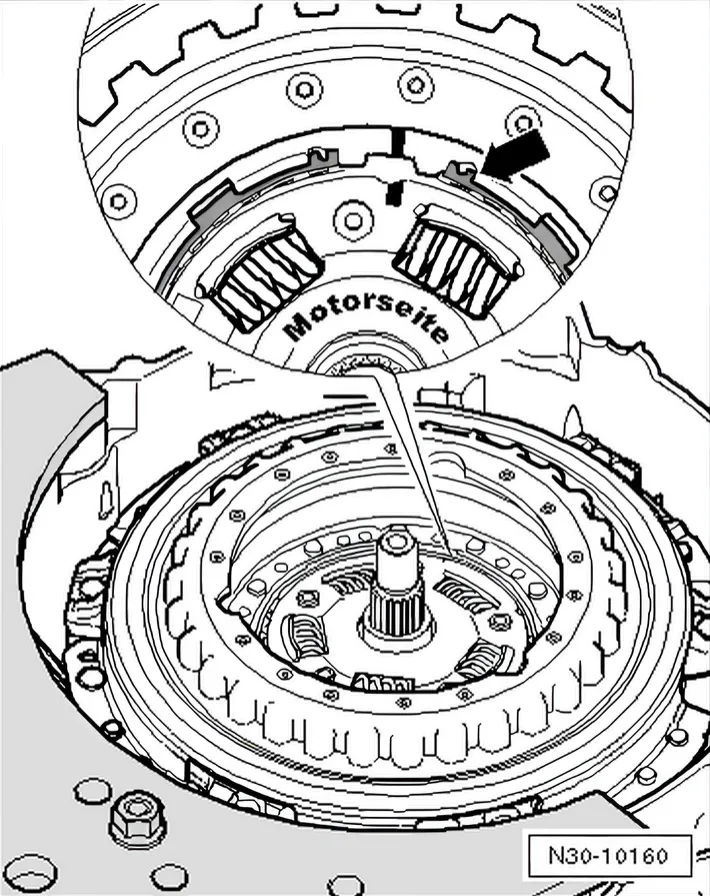
- Remove the circlip on the hub -arrow-.
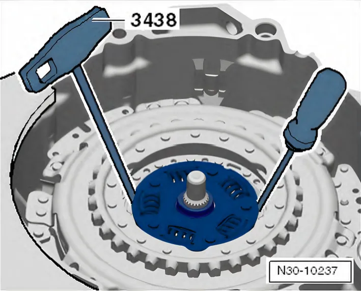
- Remove the hub using T-Handle Hook - 3438- and a screwdriver.
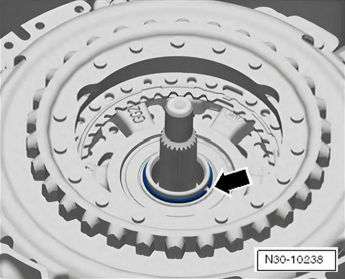
- Remove the circlip -arrow- for the clutch.
If It Is Not Possible to Remove the Locking Ring
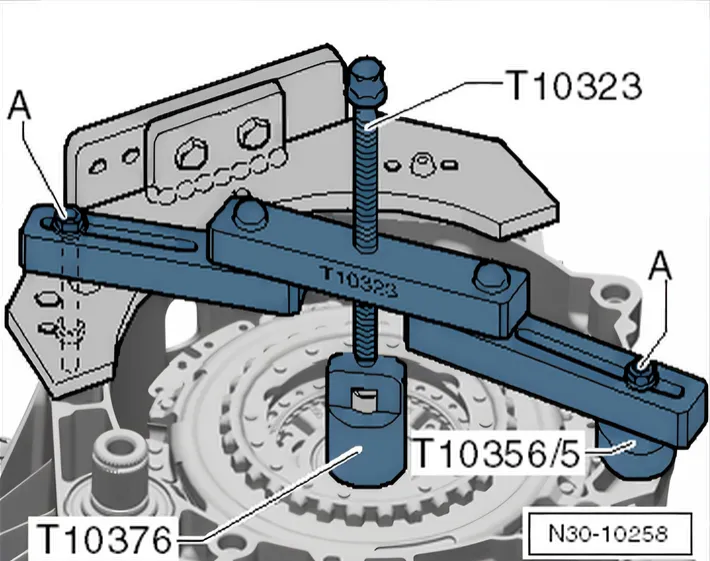
- Position the Support Bridge - T1032- parallel to the transmission flange, as illustrated.
- If necessary, even out the gaps with Assembly Tool - 5 - T10356A/5- for example.
- Tighten the bolts -A- hand-tight.
- Turn the spindle against the Clutch Press Piece - T10376- to lower it.
- Remove the locking ring -arrow- from the clutch.
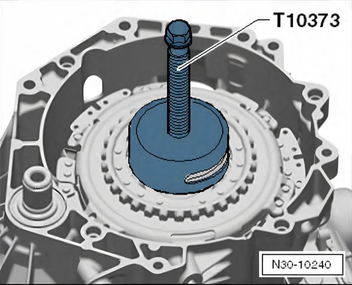
Continuation for Removing the Locking Ring
- Insert the Puller - Clutch - T10373- into the clutch and remove the clutch.
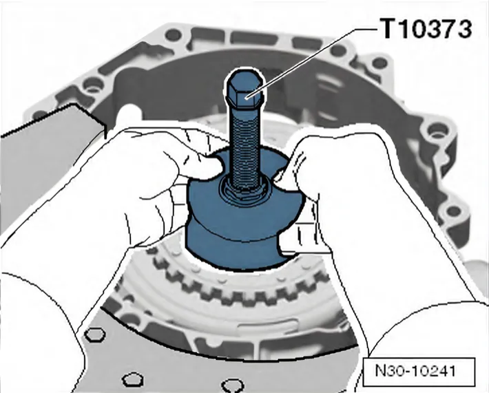
- Remove the clutch together with the Puller - Clutch - T10373-.
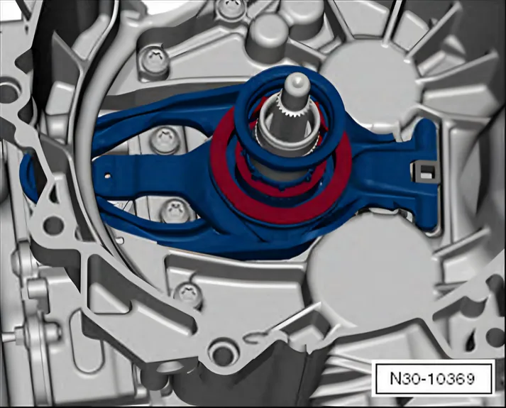
- Remove the »large« engaging lever with the »small« engaging bearing.
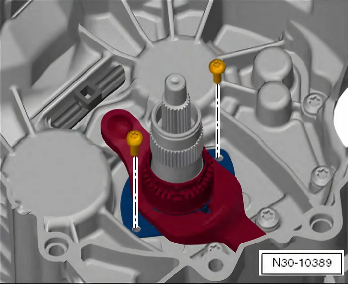
- Remove the bolts and the »small« engaging lever with the guide sleeve upper and lower sections.
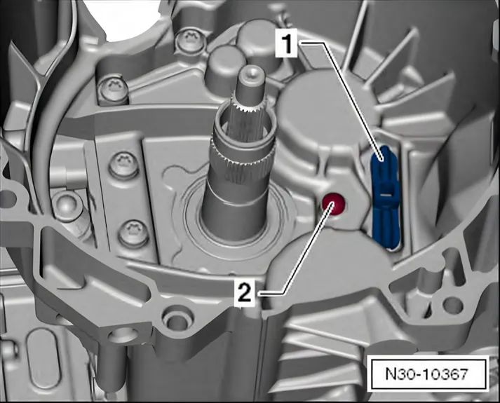
The ball stud -2- remains installed if no components are replaced.
The engaging lever support -1- is not removed.