
7-speed DSG gearbox 0AM (DQ200) · Clutch · Dual Clutch, Removing and Installing, from Transmission Production Date 06/2011
Dual Clutch, Installing, Transmission Production Date from 06/2011
Special tools and workshop equipment required
- Support Bridge - T10323-
- -T10356/5- from the Subframe Bushing Assembly Tool Kit - T10356-
- Puller - Clutch - T10373-
- Clutch Press Piece - T10376-
Installing
The hinge mount cannot be removed.
When replacing the dual clutch and its components, the “K 1 and K 2” engaging bearing position must always be readjusted. Refer to ⇒ 2.3 K 1 and K 2 Clutch Engaging Bearing Position, Adjusting, Transmission Production Date from 06/2011.
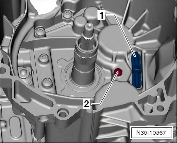
The engaging lever support -1- and ball stud -2- are installed.
The Following Procedure Is Only Then Necessary If All of the Components Mentioned are Removed and Reinstalled.
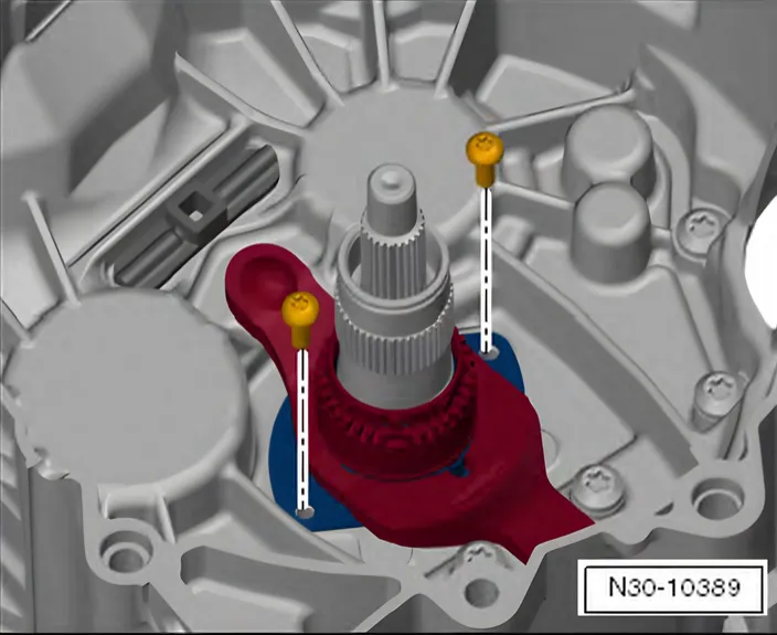
- Install the »small« engaging lever with the upper and lower sections of the guide sleeve. Install new bolts and tighten them.
Tightening specification. Refer to ⇒ 2.3 “K 1” and “K 2” Clutch Engaging Bearing Position, Adjusting, Transmission Production Date from 06/2011.
Continuation for All
Adjusting the engaging bearings can only be performed prior to installing the dual clutch.
Continue with assembling only when the adjustment is correct.
The removed shims can be used again if no new parts were installed.
Only one shim per engaging bearing can be inserted for the adjustment.
- Clutch components must have no oil or grease on them when being installed.
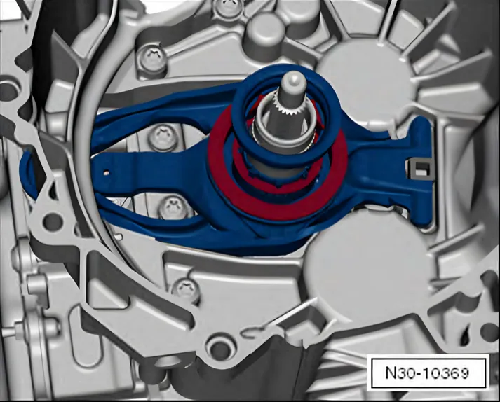
- Install the »large« engaging lever with the measured shims for “K 1” and “K 2” and with the small engaging bearing.
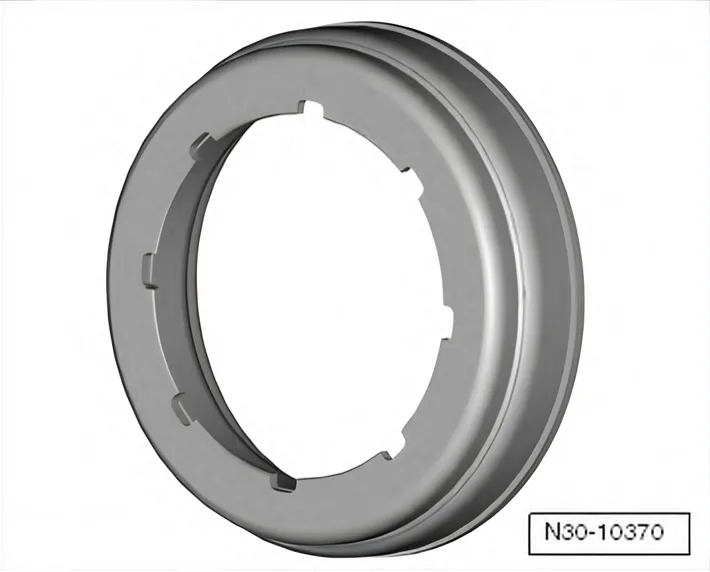
The shim and the small engaging bearing fit only in one position due to the 8 grooves.
- Turn and make sure the parts are installed correctly and fit correctly in the grooves.
- Make sure both engaging levers fit correctly.
- Turn back the Puller - Clutch - T10373- spindle.
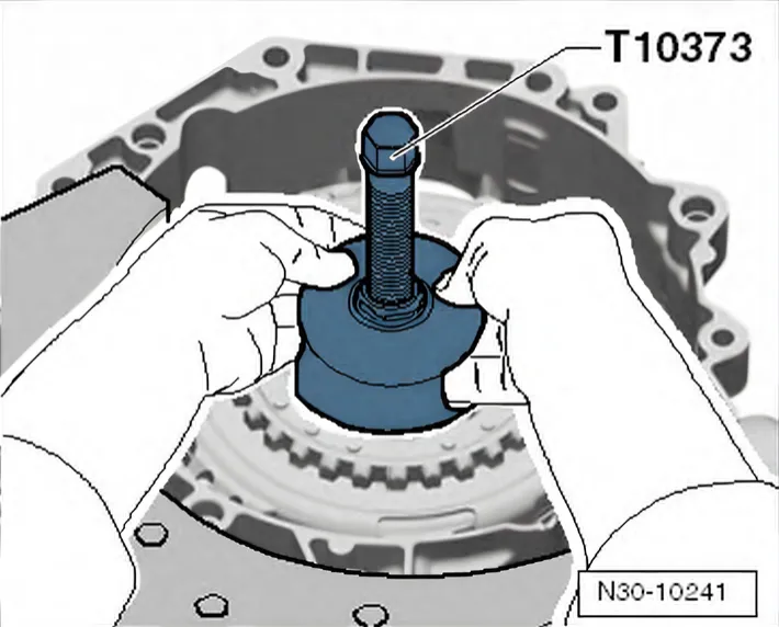
- Install the clutch in the transmission using the Puller - Clutch - T10373- as shown.
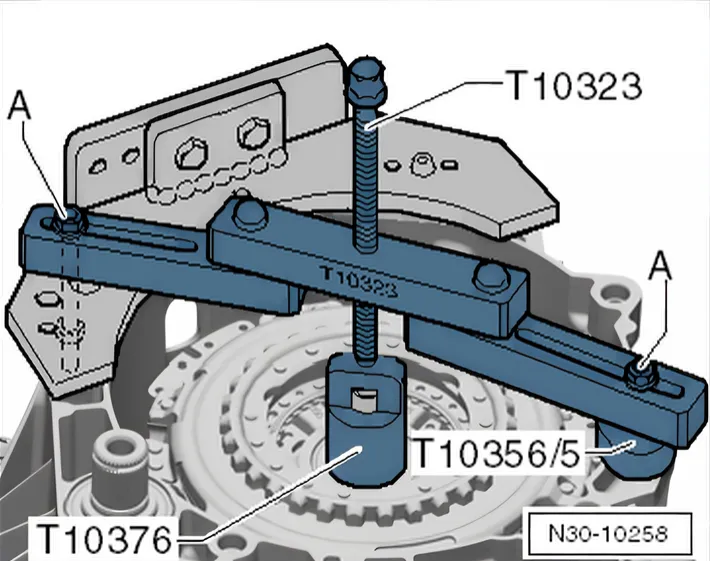
- Position the Support Bridge - T1032- parallel to the transmission flange, as illustrated.
- If necessary, even out the gaps using, for example, -T10356/5- from the Assembly Tool - T10356A-.
- Tighten the bolts -A- hand-tight.
- Install the clutch all the way.
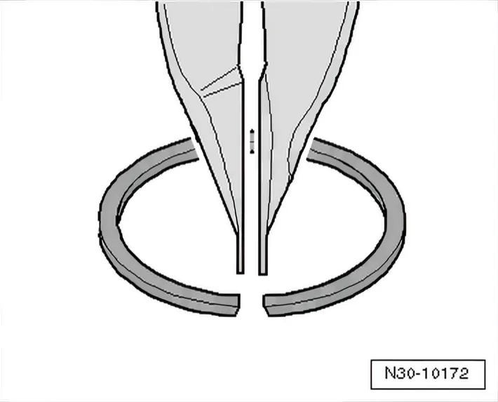
- Hold the new locking ring with locking ring pliers, as illustrated.
- Installed position: narrow ends of the locking ring at the top.
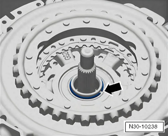
- Install the circlip -arrow-
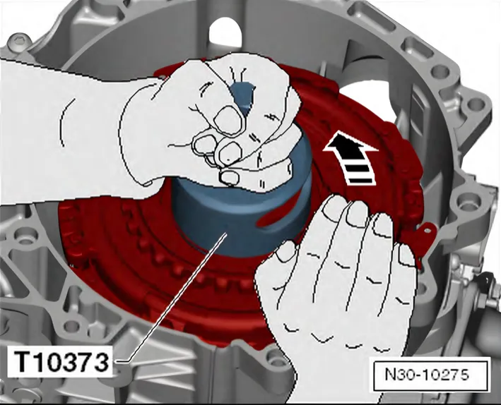
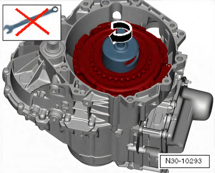
- Turn the clutch against the Puller - Clutch - T10373- by hand without using any other tools so that it can move into its operating position in direction of -arrow-.
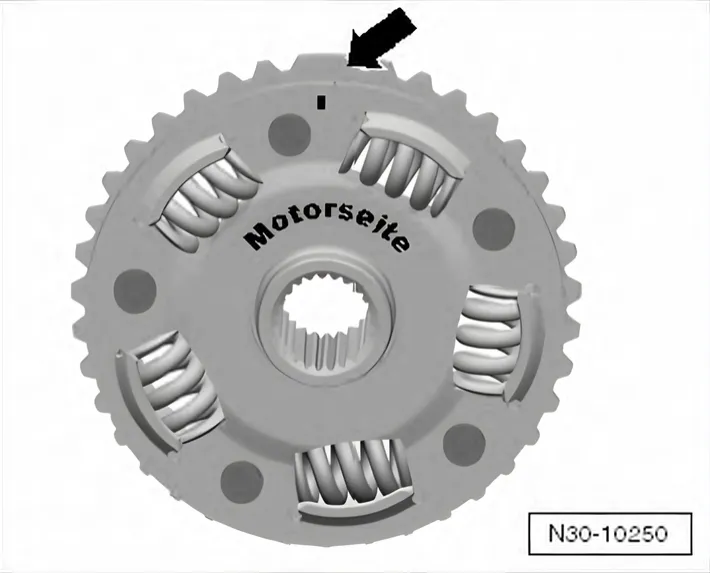
- Install the hub.
- The hub as a single »large tooth« -arrow- and fits in only one position.
- The »large tooth« has a marking on the engine side.
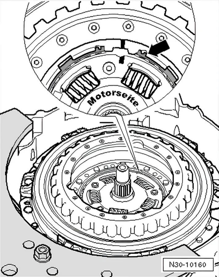
- Insert the locking ring -arrow-.
- The end of the locking ring must face the »nose« on the clutch.
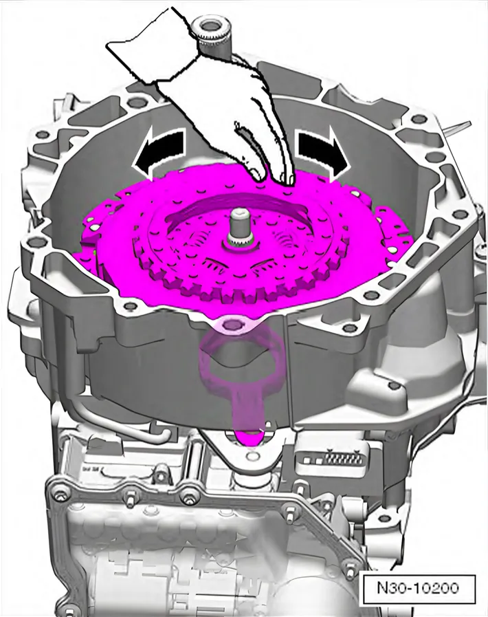
- Turn the clutch by hand. It should turn without any problem.
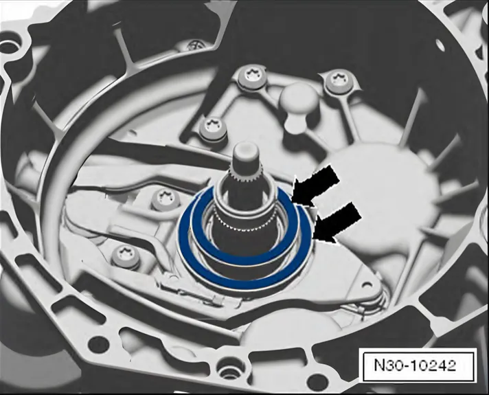
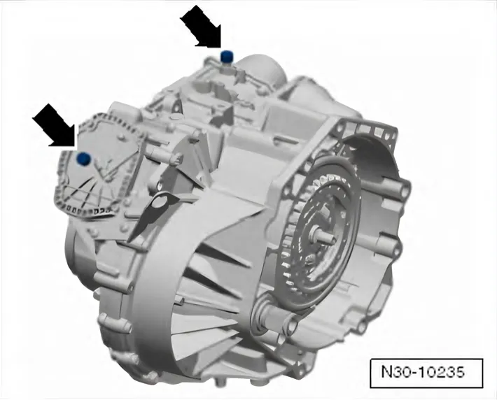
- Remove both plugs and mount the vent caps -arrows-.
- After installing the transmission, perform the Complete basic setting using Guided Functions in the Vehicle Diagnostic Tester.
огромный архив документации по автомобилям Volkswagen, Skoda, Seat, Audi