SSP 308 Direct Shift Gearbox 02E
Sensors
Gearbox input speed sender G182
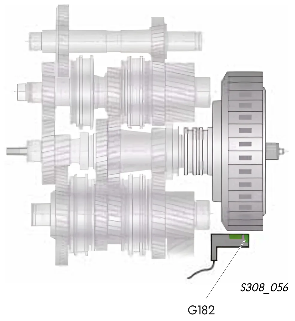
The gearbox input speed sender is inserted in the gear casing (gearbox).
It scans the outside of the double clutch and picks up the gearbox input speed.
The gearbox input speed is the same as the engine speed.
The speed sender works on the Hall sender principle. In the housing of this sender is also sender G509. Both senders are connected to the mechatronics by means of electrical wiring.
Signal application
The gearbox input speed signal is used as a figure for calculation of slip at the multi-plate clutches. To perform this calculation, the control unit also requires the signals from senders G501 and G502. The control unit is able to open and close the clutches more precisely with the aid of the clutch slip figure.
Effects of signal failure
In the event of signal failure, the control unit uses engine speed from the CAN as a substitute value.
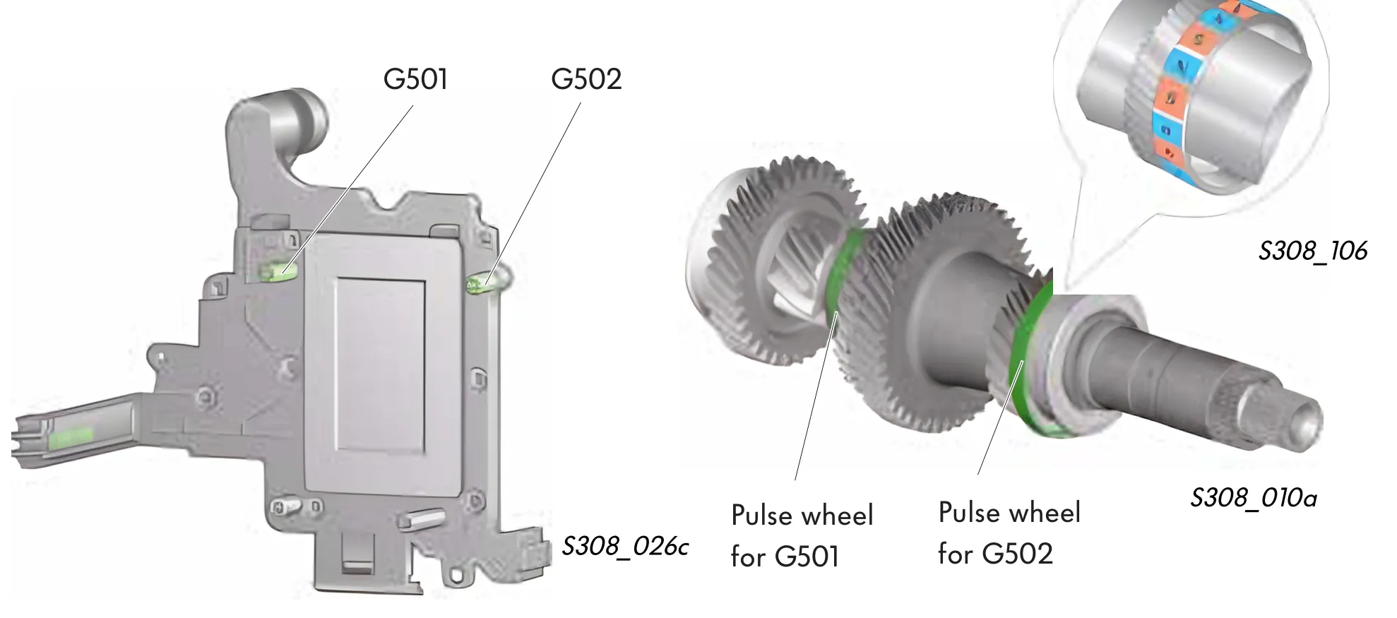
Input shaft speed sender 1 G501 and input shaft speed sender 2 G502
Both senders are located in the mechatronics. Speed sender G501 picks up the speed of input shaft 1. Speed sender G502 picks up the speed of input shaft 2. Both senders are of the Hall type.
To detect the speed, each sender scans a pulse wheel on its shaft. The pulse wheel comprises of a sheet metal element. The sheet metal element is treated with a metallic rubber coating. This coating features small magnets around its circumference, polarised to north and south. Between the individual magnets is an air gap.
Signal application
In conjunction with the gearbox input speed signal, the control unit determines the output speeds of the multi-plates clutches K1 and K2 and is therefore able to detect any slip. Using this slip figure, the control unit can detect the open/close state of the clutches. Furthermore, the signal is also used for control of the selected gear. In conjunction with the gearbox output speed sender signals, the control unit detects whether the correct gear is selected.
Effects of signal failure
If the event of signal failure, the affected gearbox section is isolated. If sender G501 fails, the vehicle can only be driven in 2nd gear. If sender G502 fails, the vehicle can only be driven in 1st and 3rd gear.
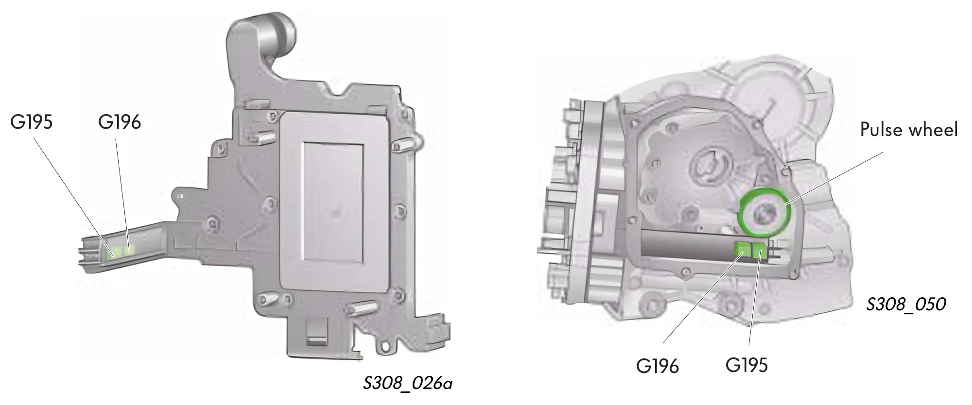
Gearbox output speed sender G195 and gearbox output speed sender 2 G196
Both senders can be found on the mechatronics and are joined permanently to the control unit. As with all speed senders in this gearbox, they are of the Hall sender type. They both scan the same pulse wheel on output shaft 2.
Both senders can be found opposed to each other in a housing. In this way, two signals offset against each other are created. If the signal from sender G195 is "high", the signal from sender G196 is "low".
Signal application
With the aid of these input signals, the control unit can detect the road speed and direction of travel. The direction of travel is detected by the signals offset against each other. If the direction of travel is changed, the signals reach the control unit in reverse order.
Effects of signal failure
In the event of signal failure, the control unit uses the road speed and direction of travel signals from the ABS control unit.
Hydraulic pressure sender 1 G193 and sender 2 G194
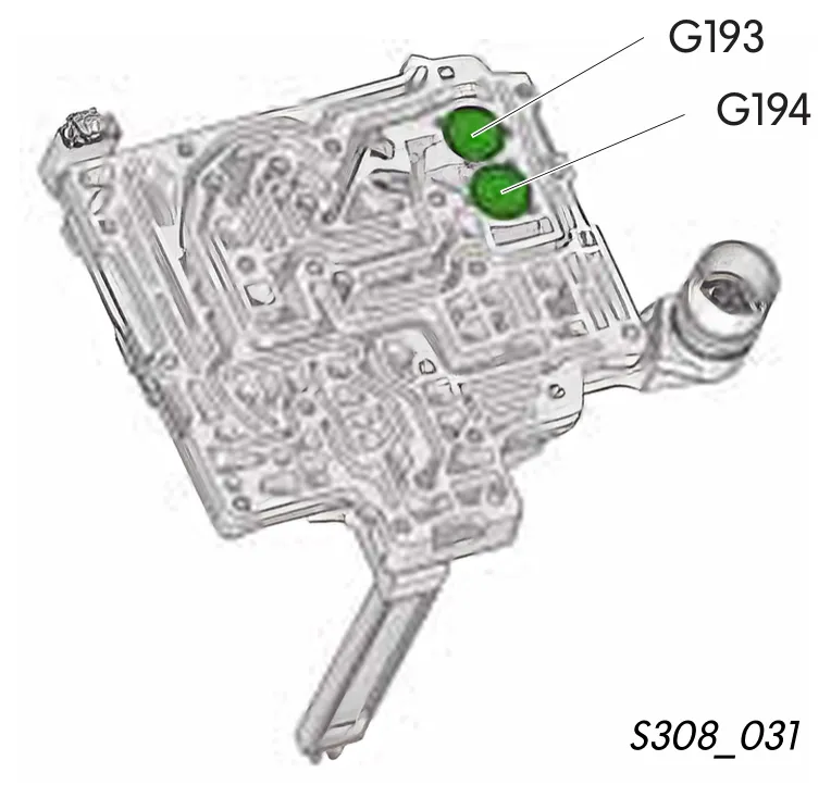
Both pressure senders can be found in the mechatronics electro-hydraulic control unit.
Sender 1 G193 is subjected to the same pressure as multi-plate clutch K1. The pressure from multi-plate clutch K2 is imparted on sender 2 G194.
Signal application
With the aid of these signals, the mechatronics control unit (ECU) detects the hydraulic pressure, which is imparted on the respective multi-plate clutch. The exact hydraulic pressure is required by the control unit for regulation of the multi-plate clutch.
Effects of signal failure
In the event of pressure signal failure or if no pressure is built up, the relevant gearbox section is isolated. The vehicle can only be driven in 1st and 3rd or in 2nd gear.
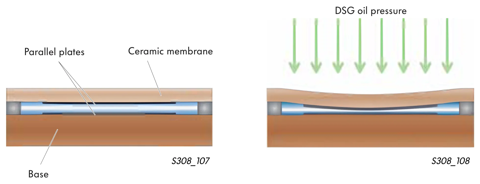
Function of pressure sender
The pressure sender comprises of a pair of electrically conductive plates in a sandwich construction. The upper plate is attached to a ceramic membrane, which bends in relation to the pressure change. The other plate is force bonded to a ceramic base. This does not react to pressure changes.
As soon as the pressure changes, the upper membrane bends and the distance between the plates changes. In this way, a reliable signal is generated based on the oil pressure.
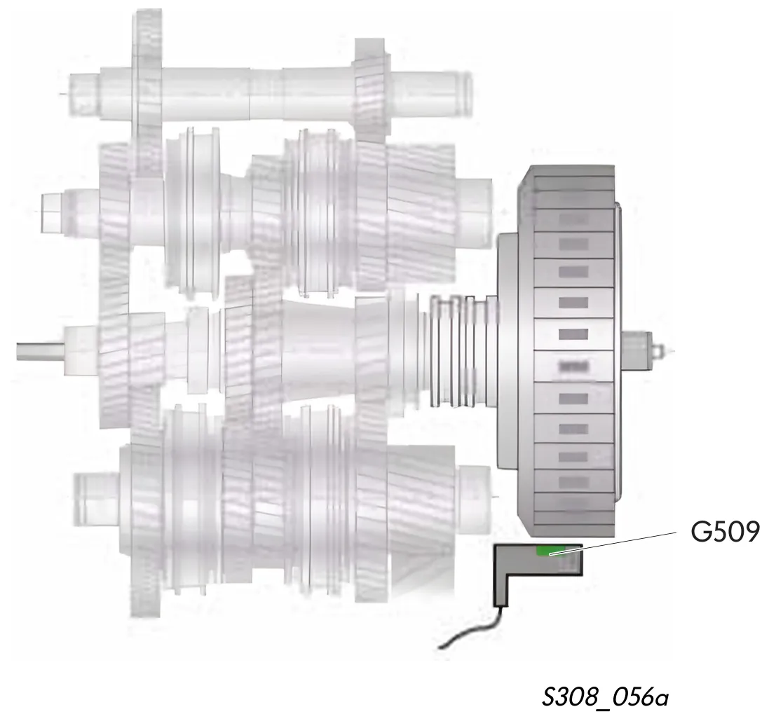
Multi-plate clutch oil temperature sender G509
The sender G509 can be found in the housing of gearbox input speed sender G182. It measures the temperature of the DSG oil at the outlet of the multi-plate clutches. Since the oil in the multi-plate clutches is placed under a large amount of thermal stress, oil reaches the highest temperature in the gearbox at this point.
This sender is designed to measure temperatures very quickly and very accurately. It operates in a temperature range of –55 °C to +180 °C.
Signal application
With the signals from temperature sensor G509, the control unit regulates the flow of clutch cooling oil and initiates further measures to protect the gearbox.
Effects of signal failure
In the event of signal failure, the control unit uses the signals from senders G93 and G510 as a substitute value.
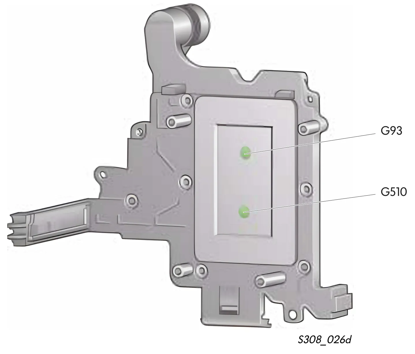
Gear oil temperature sender G93 and control unit temperature sender G510
Both senders are located directly in the mechatronics.
The mechatronics are permanently surrounded in DSG oil and are heated in this way.
An excessive rise in temperature could impair the electronic functions.
Both senders measure the temperature directly in the components that are at risk. In this way, measures can be initiated to reduce oil temperature in good time to avoid excessive heat generation in the mechatronics.
Signal application
The signals from both senders are used to check the mechatronics temperature.
In addition, the sender signals are used to start a warm-up programme.
Both senders check each other for faults.
Effects of signal failure
At gear oil temperatures in excess of 138 °C, the mechatronics initiate a reduction in engine torque. At above 145 °C, oil is no longer supplied to the multi-plate clutches and they stay open.
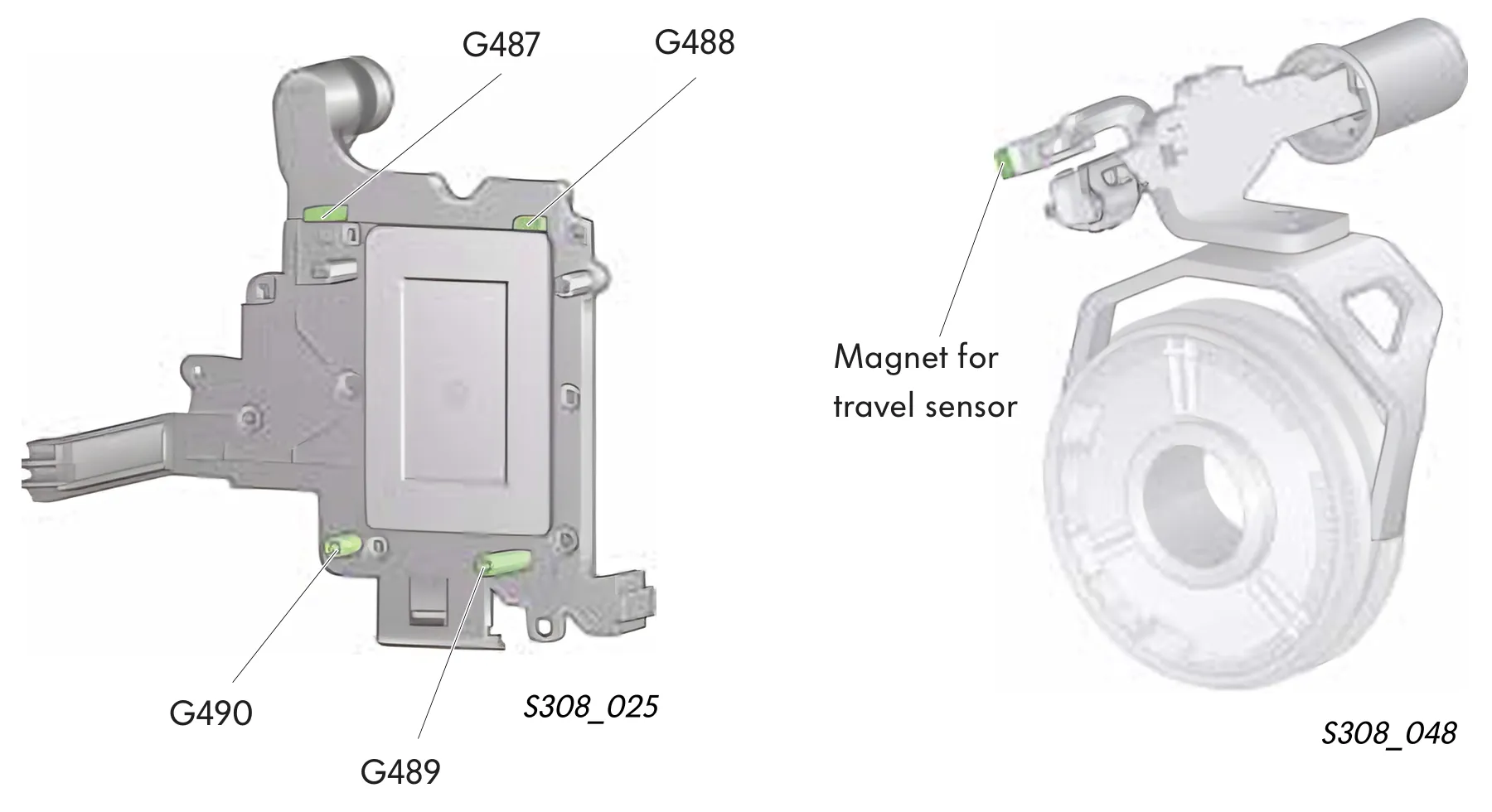
Travel sensors 1 to 4 G487, G488, G489, G490 for gear actuators
The travel sensors can be found in the mechatronics. They are of the Hall sender type. In conjunction with the magnets on the selector forks, they generate a signal which is used by the control unit to detect the position of the gear actuators.
Each travel sensor monitors the position of one gear actuator/selector fork, used to select between two gears
- G487 for 1st/3rd gears,
- G488 for 2nd/4th gears,
- G489 for 6th/reverse gears and
- G490 for 5th/neutral gears.
Signal application
The control unit imparts oil pressure on the gear actuator for selection of the gears, based on the exact position.
Effects of signal failure
If one travel sensor fails to send its signals, the affected gearbox section will be isolated. The gears of the affected gearbox section can no longer be engaged.
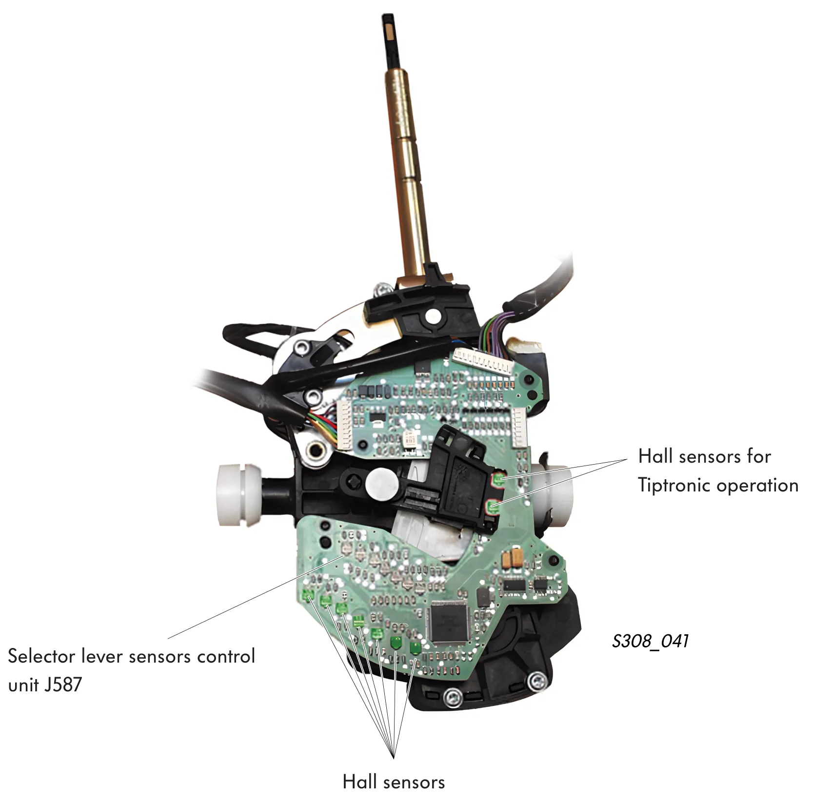
Selector lever sensors control unit J587
The selector lever sensors control unit is integrated in the selector lever. It works as a control unit and as a sensor at the same time. As a control unit it has the function of controlling the selector lever lock solenoids. The selector lever lighting is integrated within.
Also located within are the Hall senders to detect the position of the selector lever and the Hall senders to detect Tiptronic operation.
The signals from the selector lever position and the signals from Tiptronic operation are sent via the CAN bus to the mechatronics and to the dash panel insert control unit.