
SSP 308 Direct Shift Gearbox 02E
Oil lubrication circuit
The DSG has a common lubrication circuit for all gearbox functions. The volume of direct selection gear oil is 7.2 litres.
The oil must meet the following demands:
- Assure clutch regulation and hydraulic control
- Stabile viscosity across the whole temperature range
- Resistant to high mechanical stress
- Does not allow foaming
The oil has the task of:
- lubricating/cooling the double clutch, the gear wheels, shafts, bearings and parts of synchronisation and
- actuation of the double clutch and gear actuator plungers
The oil temperature is kept from rising above 135 °C by an oil cooler, which is regulated by coolant from the engine.
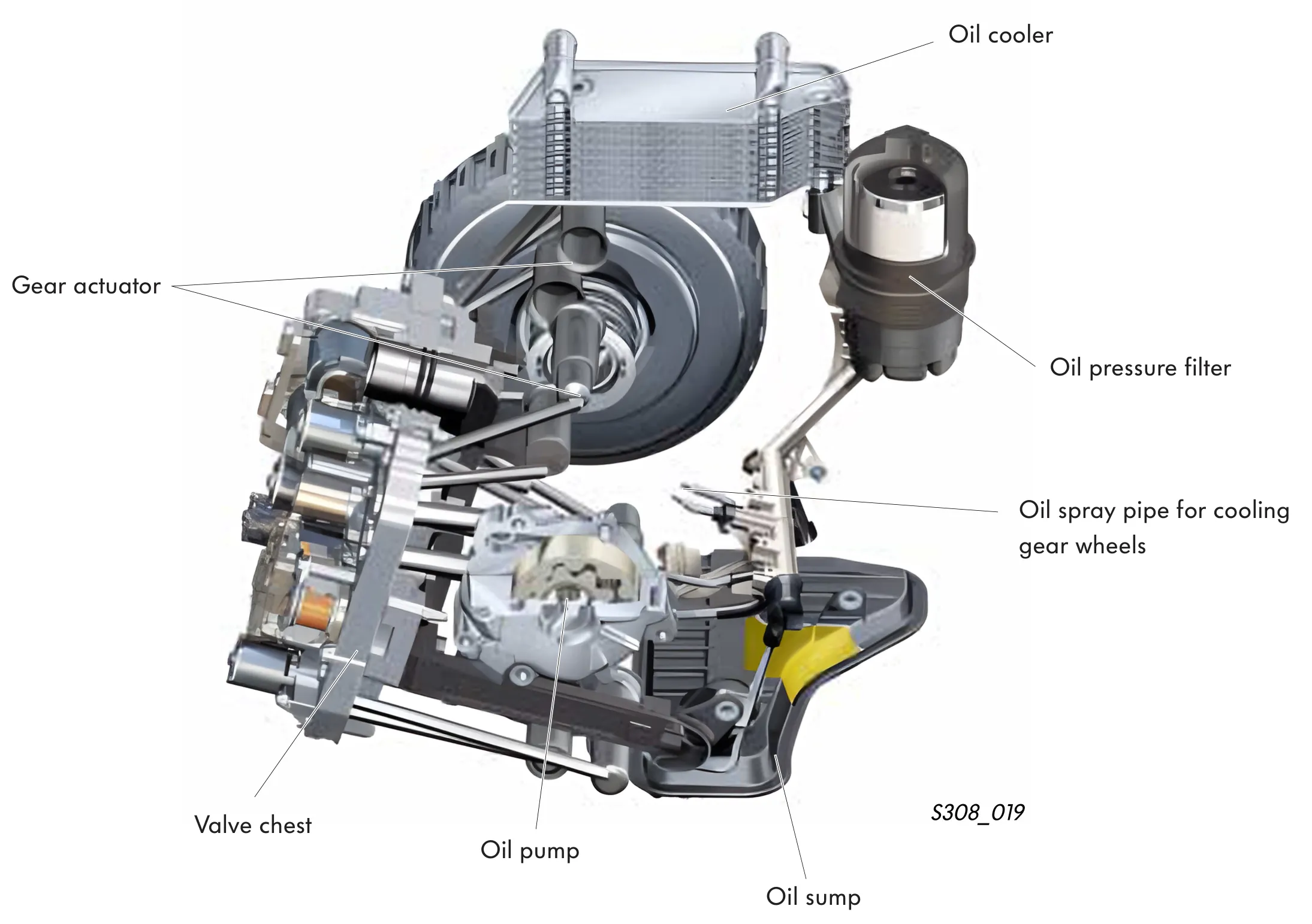
Oil pump
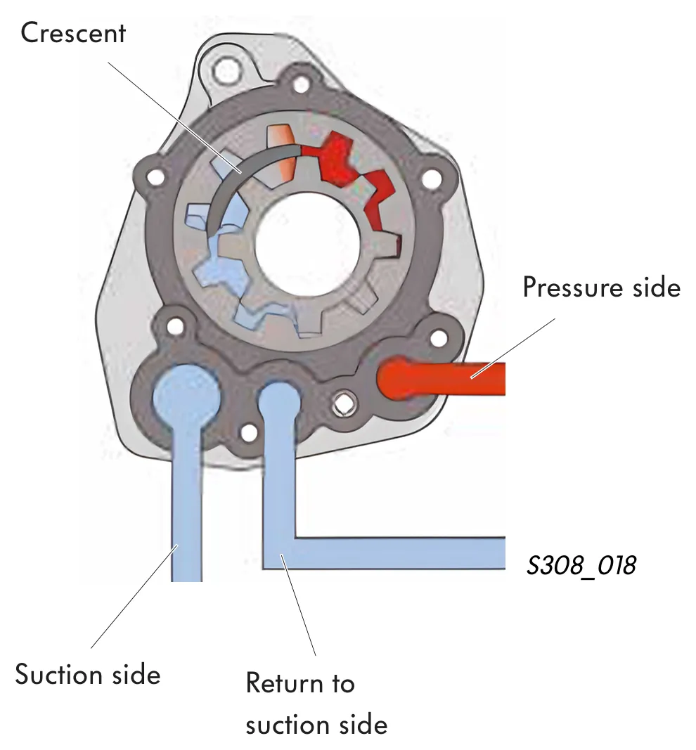
An internal gear crescent pump draws the DSG oil in and builds up the oil pressure necessary for actuation of the hydraulic components. It allows a maximum output of 100 litres per minute and a main pressure of 20 bar.
The oil pump supplies
- the multi-plate clutches
- the clutch cooling
- the gear selection hydraulics
- the gear wheel lubrication
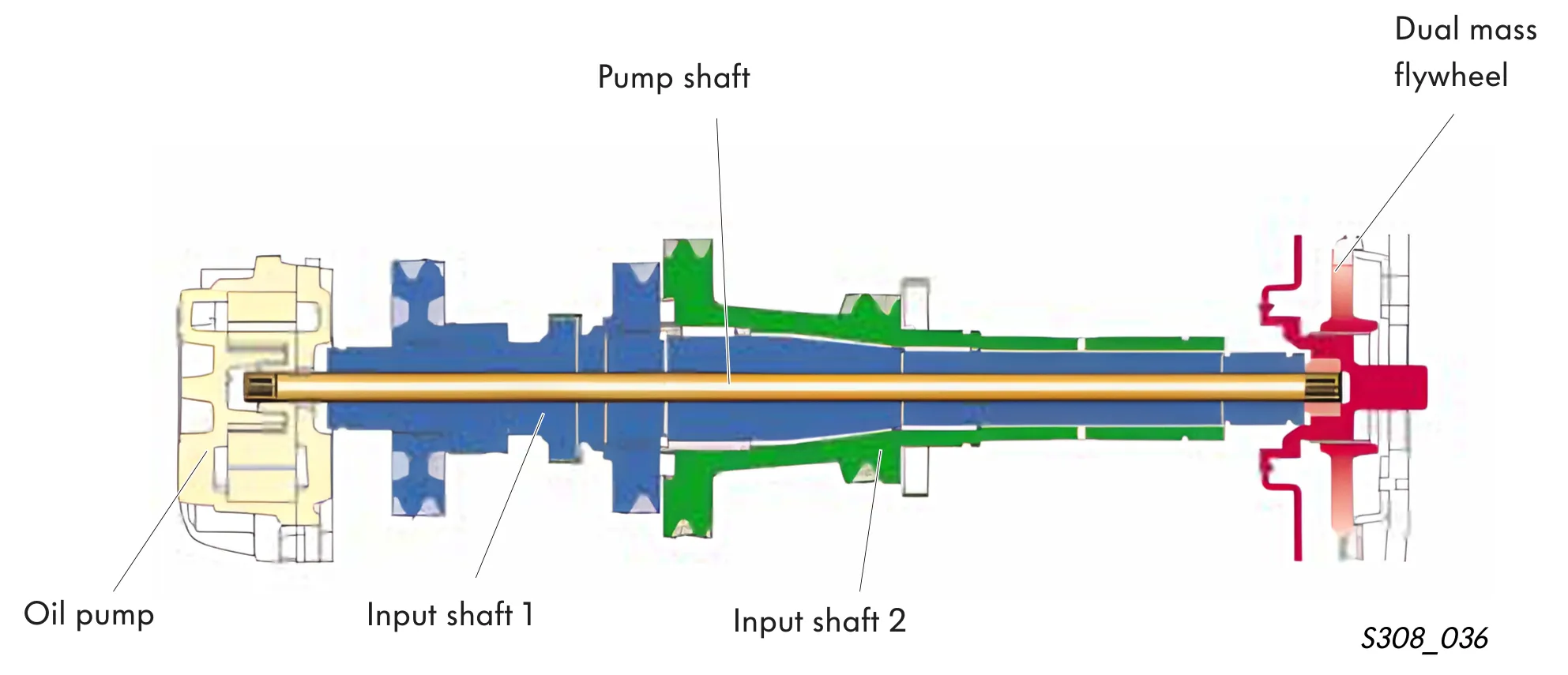
The oil pump is driven by a pump shaft, which rotates at engine speed. This pump shaft is located as a third shaft within the two meshed input shafts 1 and 2.
Oil lubrication circuit diagram
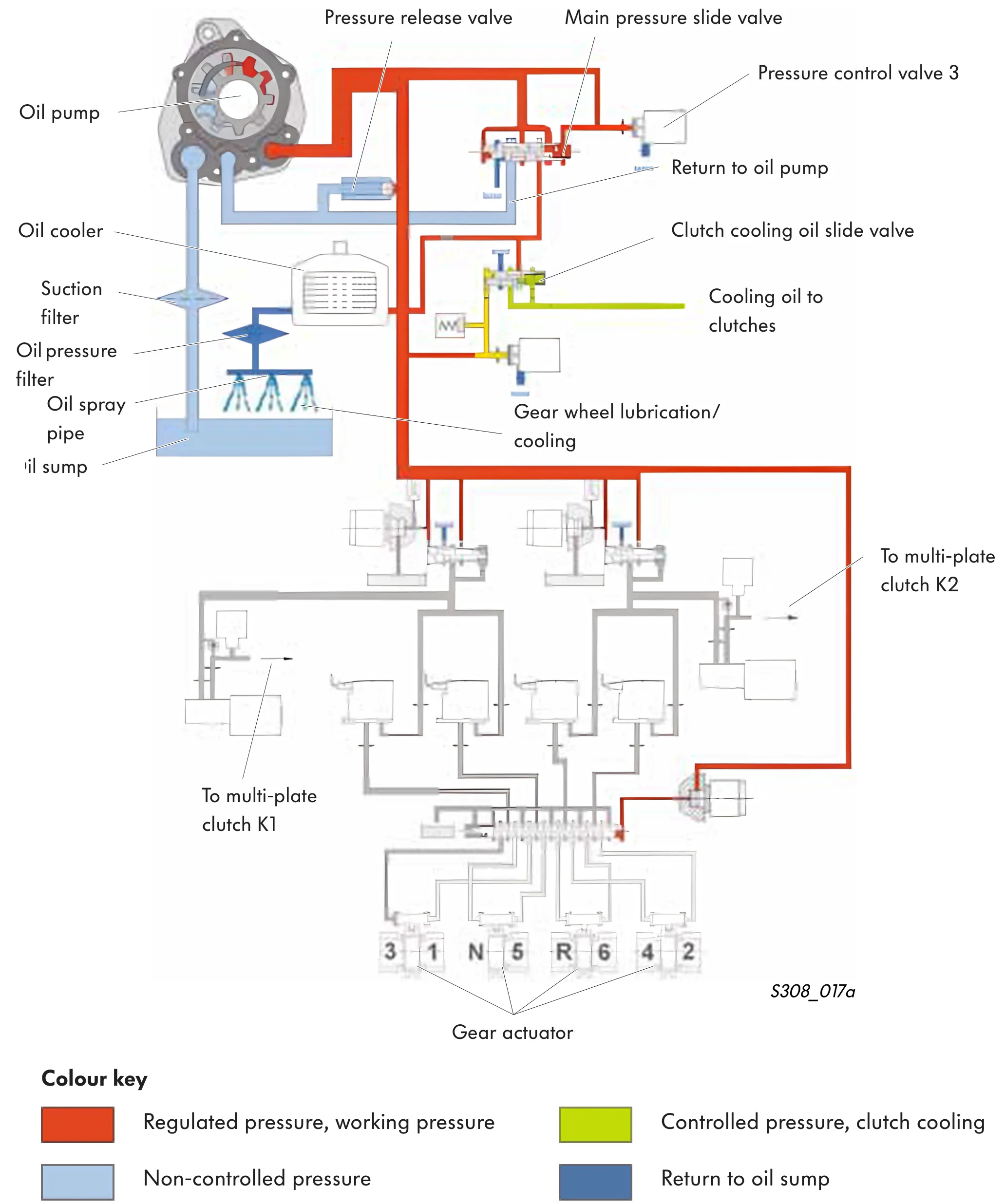
Explanation of oil lubrication circuit
The oil pump draws the oil out of the oil sump via the suction filter and supplies it under pressure to the main pressure slide valve.
The main pressure is regulated by pressure control valve 3 - the main pressure control valve. The main pressure valve controls the working pressure in the direct shift gearbox.
Beneath the main pressure slide valve is a channel that returns oil to the suction side of the pump.
The other oil channel branches off in two directions.
One channel leads to the oil cooler and then back to the oil sump via the pressure filter.
The other channel directs the flow of oil to the clutch cooling oil slide valve.
The working pressure, regulated by pressure control valve 3, is used by the gearbox to actuate the multi-plate clutches and to select the gears.
The oil cooler is incorporated in the cooling circuit of the engine.
The oil pressure filter can be found on the outside of the gear casing (gearbox).
The pressure release valve ensures that oil pressure does not rise above 32 bar.
Oil reaches the gear wheels directly by way of the oil spray pipe.
Hydraulic elements in oil lubrication circuit
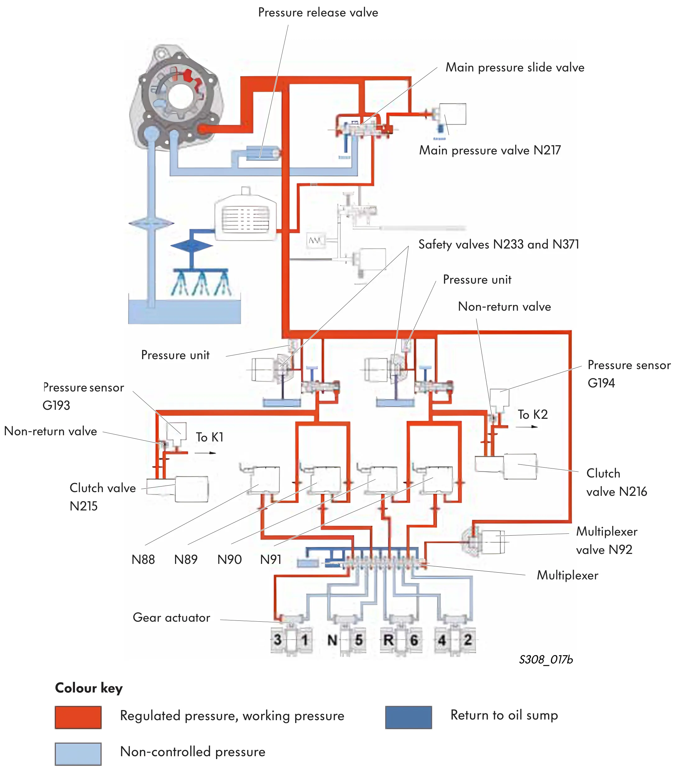
Electro-hydraulic control of oil lubrication circuit
Main pressure valve N217
This valve is actuated by the electronic control unit and it controls the main pressure slide valve.
In this way, the working pressure in the direct shift gearbox hydraulic system is regulated.
The flow of oil
- through oil cooler/pressure filter/spray pipe,
- back to oil pump
is controlled by the main pressure valve.
Main pressure is made available to both clutch valves N215 and N216 to open and close the clutches K1 and K2 and to the four gear actuator valves N88, N89, N90 and N91 for gear engagement.
Multiplexer valve N92
This valve actuates the multiplexer. The multiplexer (multiplier) allows control of the eight gear actuator cylinders using just four solenoid valves.
The multiplexer is pushed into its base position by means of a spring.
In the base position, 1st, 3rd, 6th and reverse gears can be selected.
If the multiplexer valve N92 is energised, oil pressure is free to flow to the multiplexer. This results in the multiplexer being pressed against spring pressure into the operating position.
In this way, 2nd, 4th, 5th and neutral gears can be selected.
Safety valves
One safety valve each for clutch K1 (N233) and clutch K2 (N371) allow rapid opening of each respective clutch. This becomes necessary if and when the actual clutch pressure rises above the specified pressure.
Pressure sensors G193 and G194
The pressure sensors G193 and G194 control the clutch pressure of clutches K1 and K2.
A pressure release valve prevents excessive rise in main pressure in the event of a defective main pressure slide valve.