
1.6 TDI CR engine (EA189) · Removing and installing engine · Removing and installing engine
Removing engine
1.1.1 Removing engine, Polo
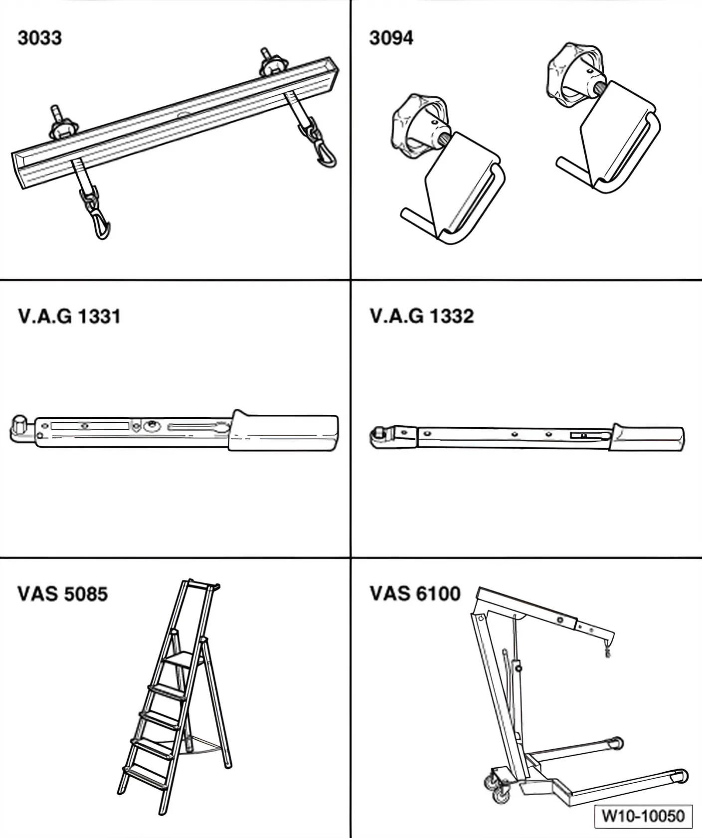
Special tools and workshop equipment required
- Lifting tackle - 3033-
- Hose clamps, up to 25 mm - 3094- (only for vehicles with manual gearbox)
- Torque wrench - V.A.G 1331-
- Torque wrench - V.A.G 1332-
- Stepladder - VAS 5085-
- Workshop hoist - VAS 6100-
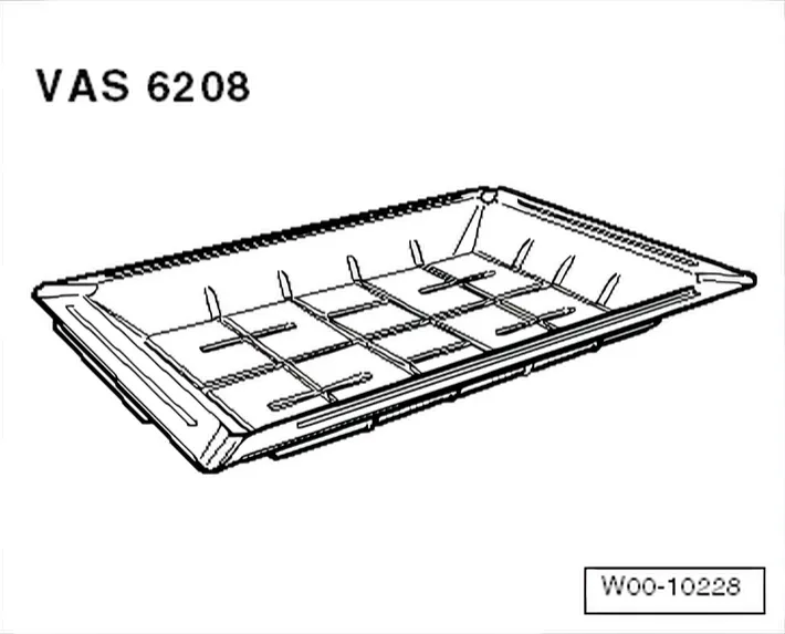
- Drip tray for workshop hoist - VAS 6208-
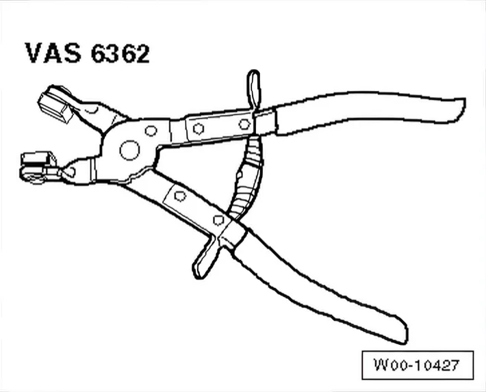
- Pliers for spring-type clips - VAS 6362-
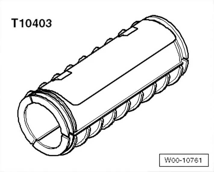
- Transportation lock - T10403-
- Engine bung set - VAS 6122- (not shown)
Removing
- Remove engine cover panel ⇒ 3 Engine cover panel.
- With ignition switched off, disconnect battery earth strap. ⇒ Electrical system; Rep. gr. 27; Battery; Disconnecting and connecting battery
Polo
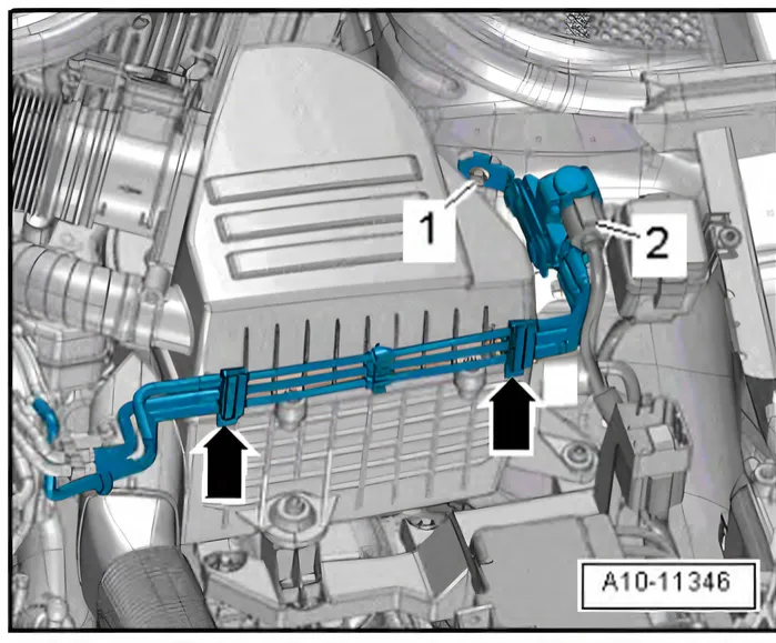
- Disconnect connector -2-.
- Unscrew bolt -1-.
- Expose vacuum hoses -arrows- and place charge pressure control solenoid valve - N75- on the engine.
Continuation for all vehicles
- Remove air filter housing with air mass meter and connecting pipe.
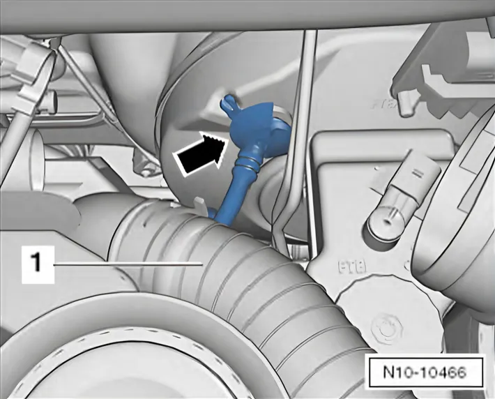
- Detach vacuum line -arrow- on brake servo.
- Remove noise insulation:
Polo ⇒ General body repairs, exterior; Rep. gr. 50; Noise insulation; Assembly overview - noise insulation
- Drain coolant ⇒ 1.3 Draining and adding coolant.
Vehicles with air conditioning system
- Extract refrigerant from air conditioning system ⇒ Heating, air conditioning system; Rep. gr. 00; Repair instructions; Draining the refrigerant circuit.
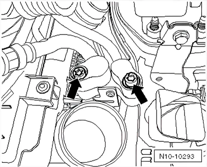
- Unbolt refrigerant lines -arrows- at condenser ⇒ Heating, air conditioning; Rep. gr. 87; Refrigerant circuit; Disconnecting and connecting refrigerant lines.
Continuation for all vehicles
- Remove lock carrier ⇒ General body repairs, exterior; Rep. gr. 50; Lock carrier; Removing and installing lock carrier.
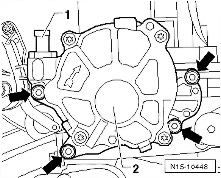
- Detach vacuum line -1- from vacuum pump -2-.
Polo
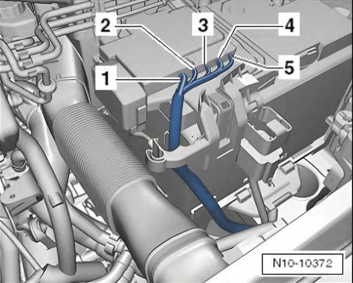
- Unbolt positive cable -1- at positive distributor on battery.
- Place cable on engine.
- Remove air filter housing with air mass meter and connecting pipe ⇒ 7.2.2 Removing and installing air filter housing, Polo.
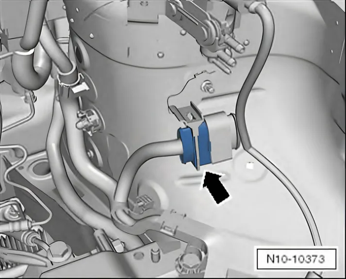
- Disconnect connectors -arrow-.
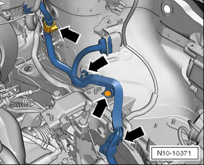
- Carefully loosen engine wiring harness at its fastening points -arrows-.
- Place engine wiring harness on engine.
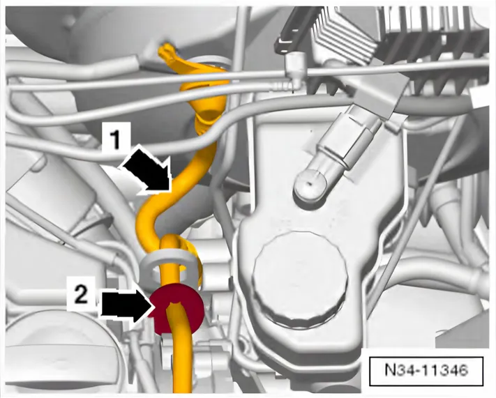
- In order to ensure that vacuum hose -arrow 1- from brake servo to engine is not damaged, you must remove it ⇒ Brake systems; Rep. gr. 47; Brake servo/brake master cylinder; Assembly overview - brake servo/brake master cylinder.
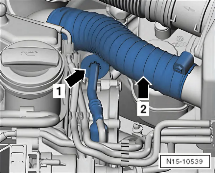
Pre-heater line -arrow 2- is not necessarily installed.
- Separate connectors at engine control unit ⇒ 9 Engine control unit.
- Disconnect connectors.
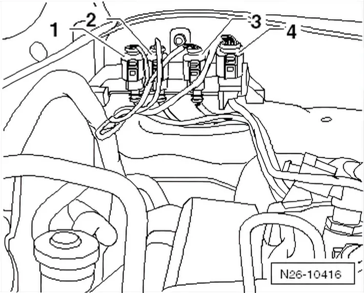
- -1- Exhaust gas temperature sender 1 - G 235-
- -2- Exhaust gas temperature sender 3 - G 495-
- -3- Exhaust gas temperature sender 4 - G 648-
- -4- lambda probe - G 39-
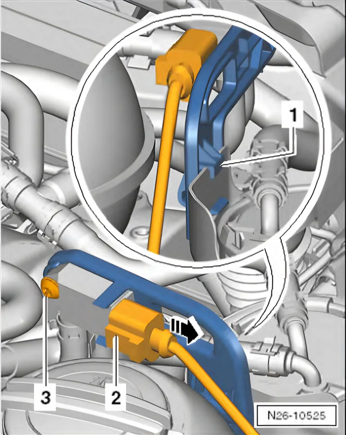
- Disconnect electrical connector -2- at pressure differential sender - G 505-.
- Unscrew bolt -3- from pressure differential sender - G 505- bracket.
- Lay pressure differential sender - G 505- aside to rear together with lines.
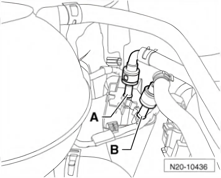
- Separate fuel supply line and return line at fuel transfer point.
The procedure for this is explained in ⇒ Rep. gr. 20; Detaching plug-in connector.
- Collect any escaping fuel.
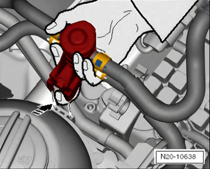
- Using a finger, release lug from fuel pre-heater valve.
- Pull fuel pre-heater valve upwards out of coolant expansion tank guide.
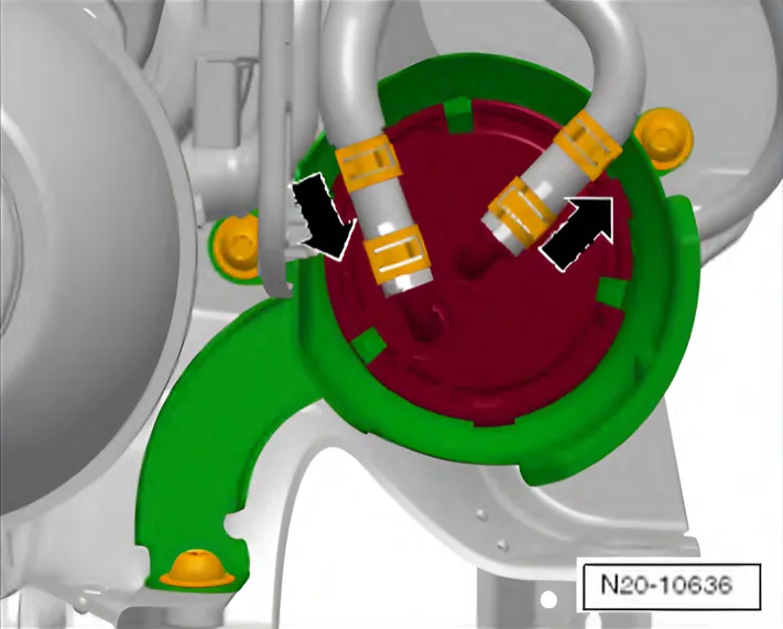
- Unclip fuel filter from lower part of fuel filter.
- Take fuel filter out upwards.
- Place fuel filter and fuel hoses together with fuel pre-heater valve on engine.
- Remove lower part of fuel filter ⇒ Rep. gr. 20; Fuel filter; Removing and installing fuel filter.
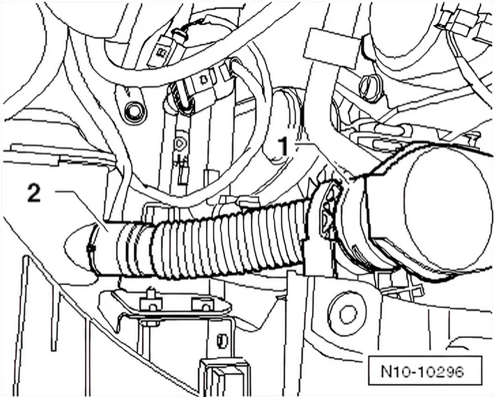
- Filler neck: Unclip windscreen washer system reservoir -1-.
- Filler neck: Unclip windscreen washer system reservoir -2-.
Vehicles with air conditioning system
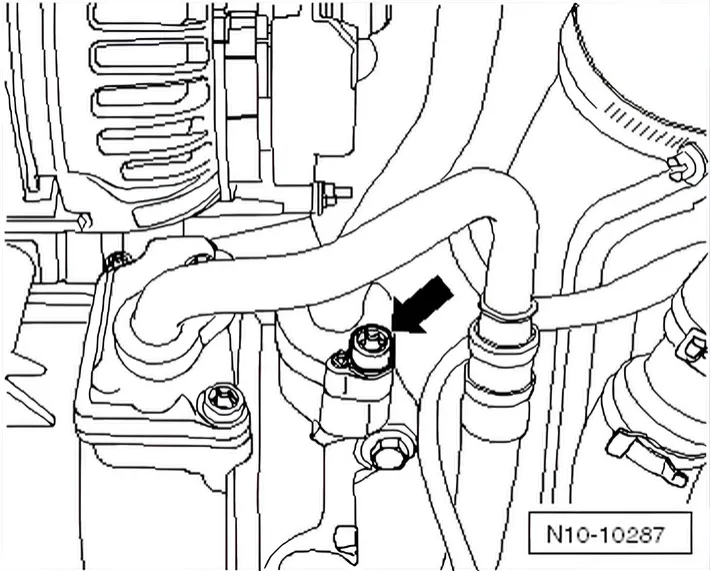
- During further procedure, unscrew securing bolt for refrigerant line -arrow- from air conditioner compressor ⇒ Heating, air conditioning; Rep. gr. 87; Air conditioner compressor; Removing and installing refrigerant lines from and to air conditioner compressor.
- Pull off refrigerant line at air conditioner compressor and lay it aside without kinking.
Continued for all vehicles
- Remove coolant expansion tank and lay down on engine.
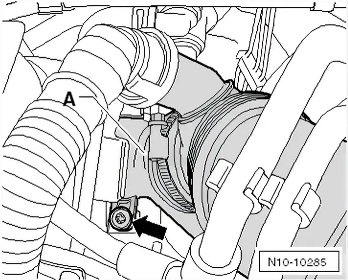
- Unscrew bolt -arrow- (attached), unscrew intake hose -A- clockwise out of its bracket and remove.
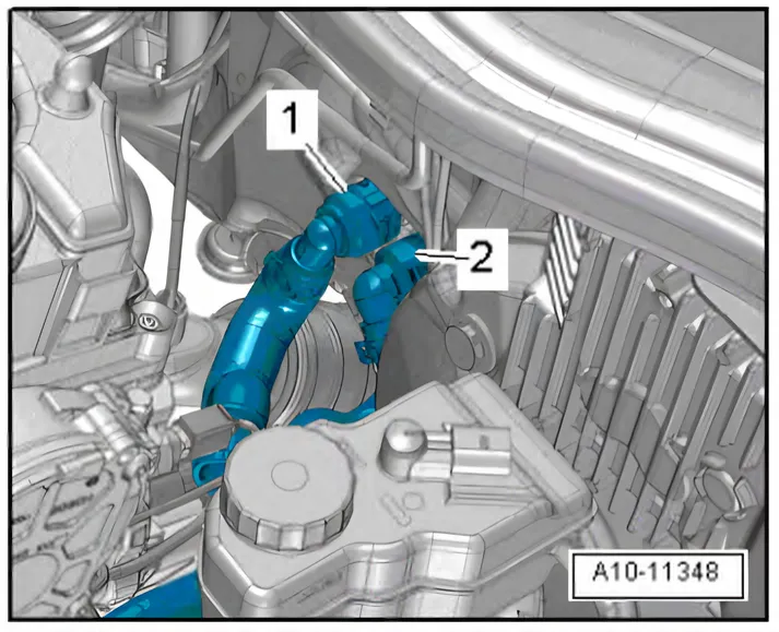
- Disconnect coolant hoses from heat exchanger for heater. Lift retaining clips -1, 2- to do this.
Vehicles with dual clutch gearbox:
- Remove selector mechanism from gearbox ⇒ Rep. gr. 34; Selector mechanism; Removing and installing selector mechanism.
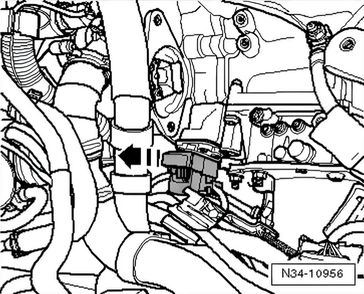
- Release catch on mechatronic connector by pulling -arrowand pull connector off.
Vehicles with manual gearbox:
- Remove selector mechanism from gearbox ⇒ Rep. gr. 34; Selector mechanism; Removing and installing selector mechanism.
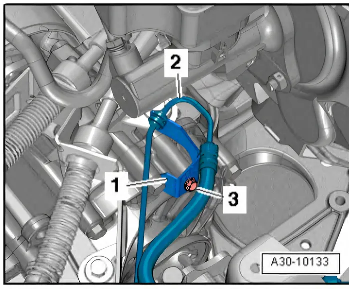
- Unscrew bolt -3-.
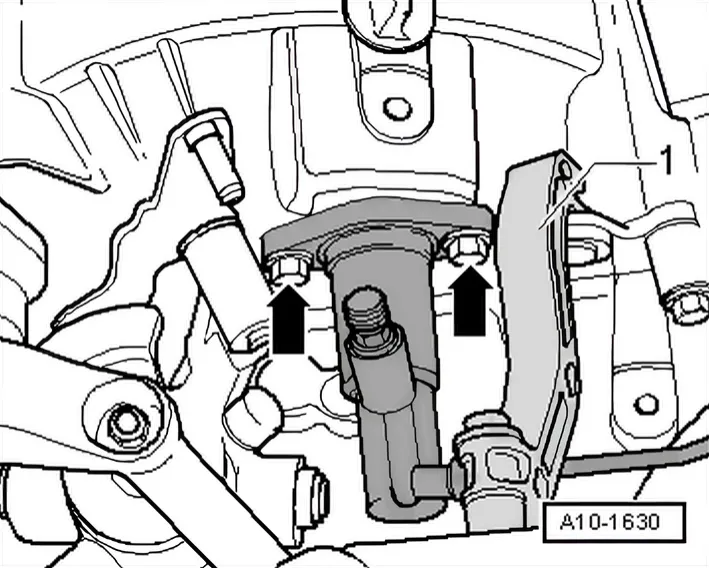
- Remove bolts -arrows- and lay clutch slave cylinder aside. Do not open hydraulic system.
- Guide clutch slave cylinder under strut -1-.
Continued for all vehicles
- Unbolt earth cable on gearbox.
- Disconnect all connectors between starter, gearbox and body.
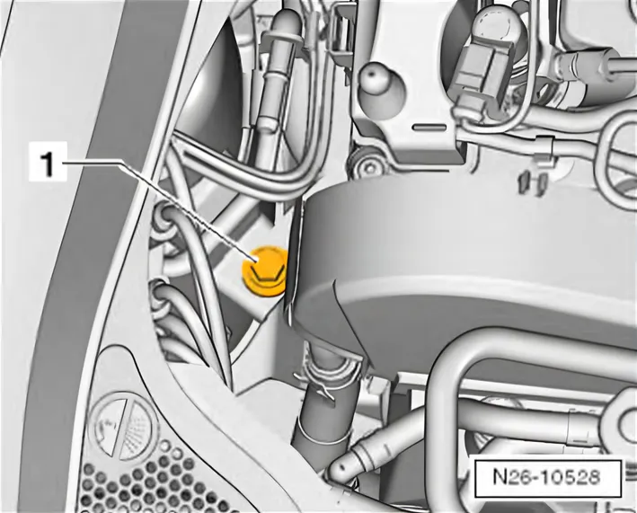
- Unscrew bolt -1-.
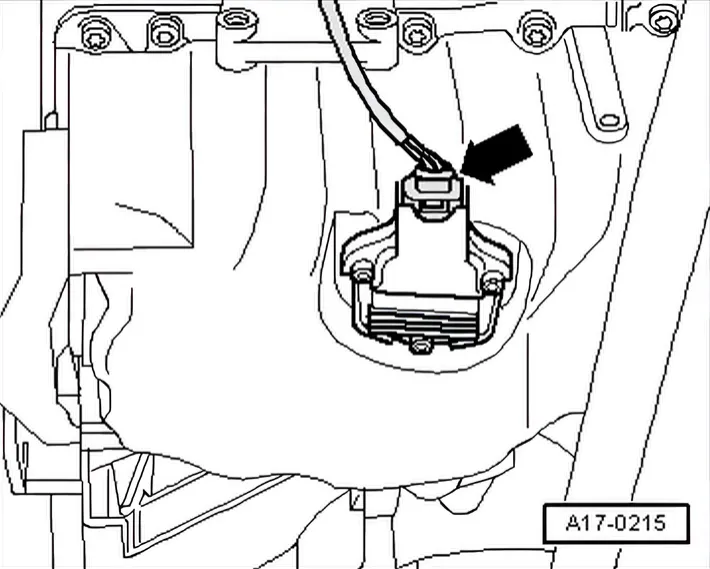
- Detach connector from oil level and oil temperature sender - G266-.
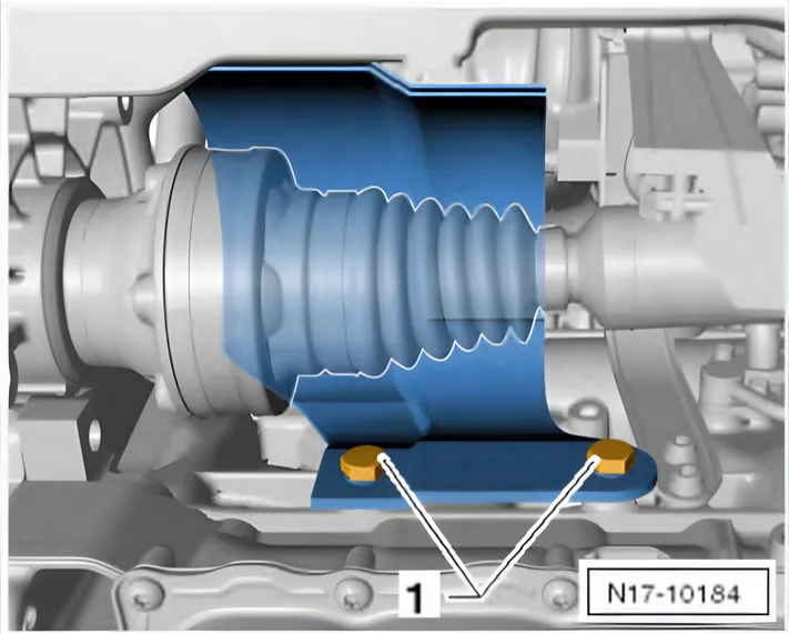
- Remove right drive shaft cover.
- Remove drive shafts from gearbox ⇒ Running gear, axles, steering; Rep. gr. 40; Drive shaft; Removing and installing drive shaft.
- Raise and tie drive shafts as high as possible.
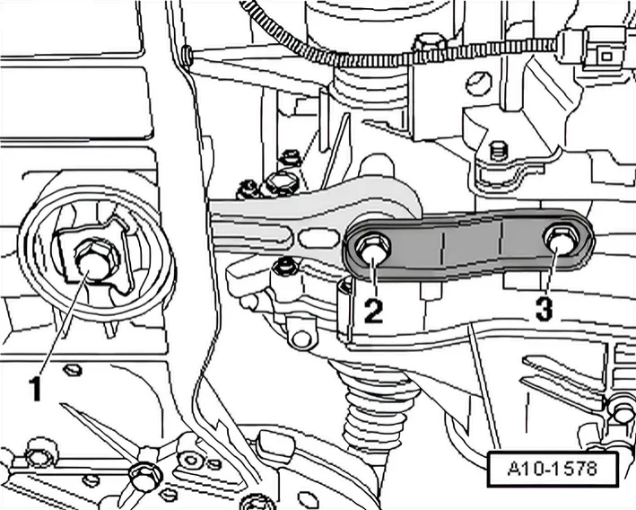
- Remove bolts -2…3-.
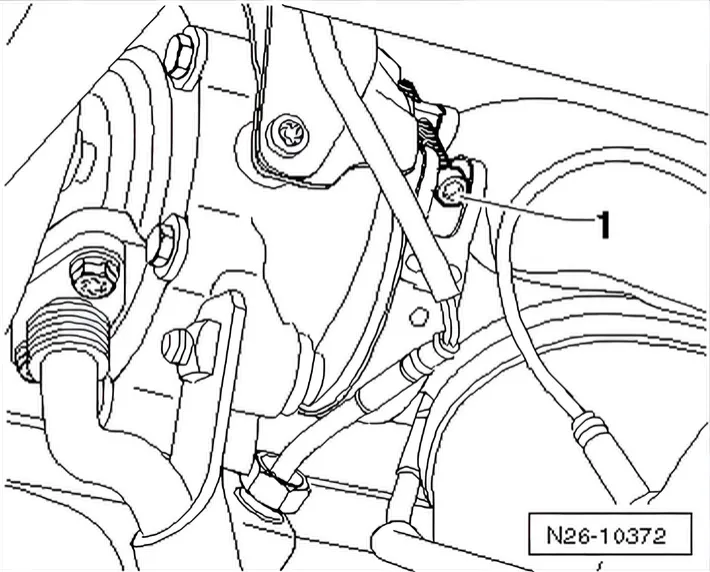
- Remove securing clamp -1- between particulate filter and turbocharger.
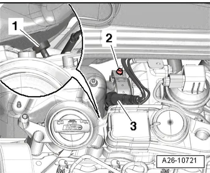
- If necessary, securing clamp -2- between particulate filter and turbocharger must also be removed from above.
Polo
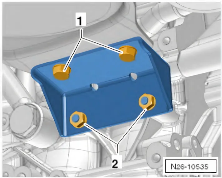
- Unscrew bolts -1- and nuts -2-.
- Remove particulate filter bracket.
Continued for all vehicles
- Push particulate filter aside and fix it in position on plenum chamber bulkhead using suitable means.
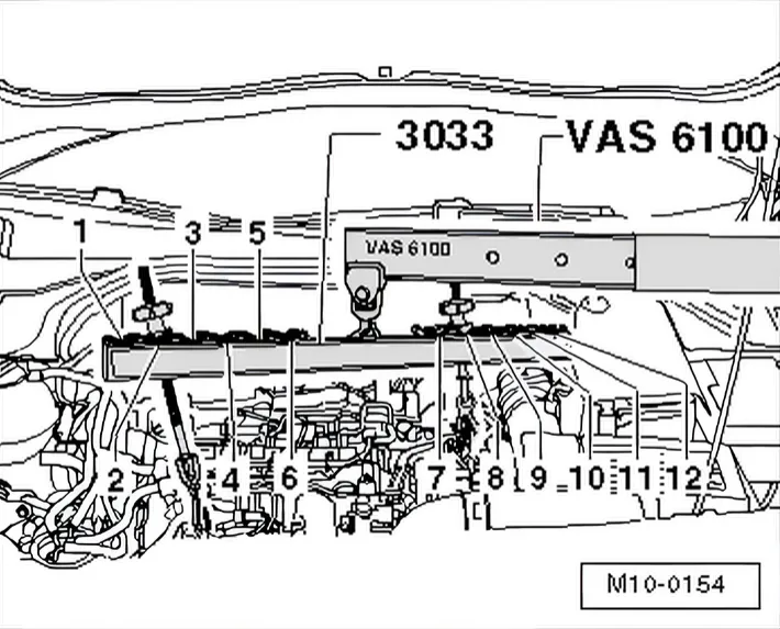
- Use lifting tackle - 3033- and workshop hoist - VAS 6100- to support »engine/gearbox assembly« in installation position.
Vibration damper end:
- Item 2.
Flywheel end:
- Item 8.
Polo
Remove complete engine assembly mounting ⇒ 2.1.3 Removing and installing assembly mountings.
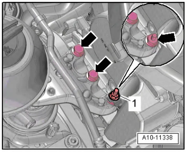
- Unscrew nut -1- and expose earth line
Remove assembly mounting at gearbox.
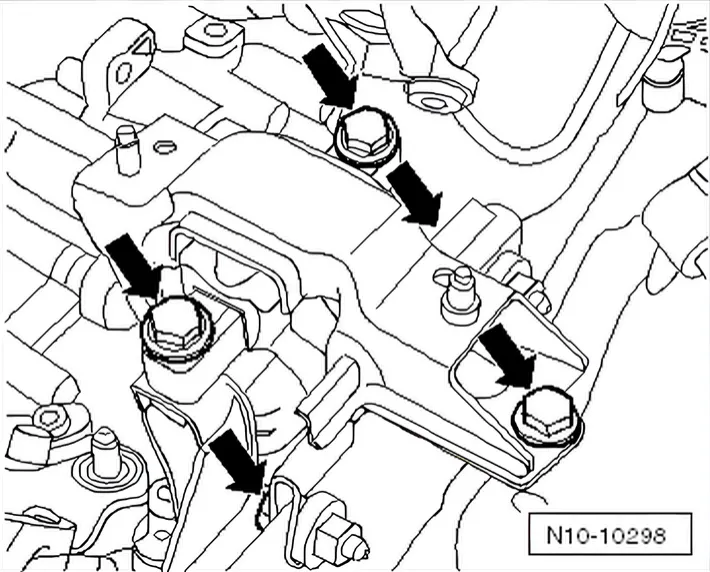
- To do this, unscrew bolts -arrows- for support arm of engine mounting.
Continued for all vehicles
- Slightly lift »engine/gearbox assembly« and remove forwards.
Secure engine on engine and gearbox support - VAS 6095- to carry out repairs ⇒ 1.3 Securing engine on engine and gearbox support.