
1.6 TDI CR engine (EA189) · Removing and installing engine · Assembly mountings
Assembly mountings – assembly overview and fastening
⇒ 2.1.2 Assembly overview – assembly mountings, Polo
2.1.2 Assembly overview – assembly mountings, Polo
- Removing and installing assembly mountings ⇒ 2.1.3 Removing and installing assembly mountings
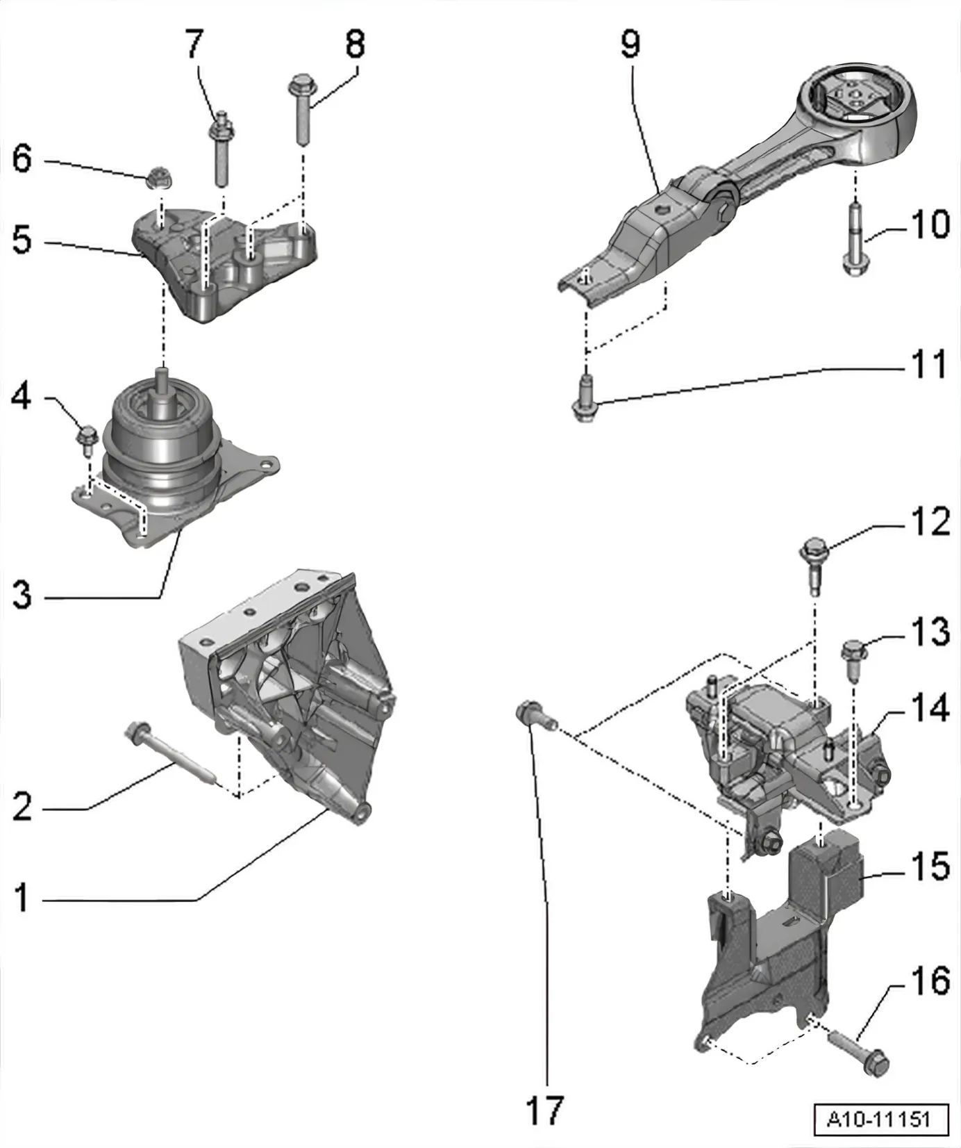
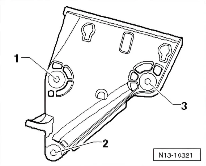
- 1 Engine support
- 2 Bolt
- Specified torque and tightening sequence ⇒ 2.1.2 Assembly overview – assembly mountings, Polo
- 3 Assembly mountings
- Removing and installing ⇒ 2.1.3 Removing and installing assembly mountings
- 4 Bolt
- Renew
- 20 Nm +90°
- 5 Support arm
- 6 Nut
- May only be unscrewed to renew engine mounting -item 3-
- Renew
- 40 Nm +90°
- 7 Threaded pin
- Renew
- 30 Nm +90°
- 8 Bolt
- Renew
- 30 Nm +90°
- 9 Pendulum support
- 10 Bolt
- Pendulum support to sub-frame
- Tightening torque ⇒ Rep. gr. 40; Subframe, anti-roll bar, suspension link
- 11 Bolt
- Pendulum support to gearbox
- Tightening torque ⇒ Rep. gr. 40; Subframe, anti-roll bar, suspension link
- 12 Bolt
- Gearbox mounting to body
- Specified torque ⇒ Rep. gr. 34; Assembly mountings; Assembly overview - assembly mountings
- 13 Bolt
- Gearbox mounting to body
- Specified torque ⇒ Rep. gr. 34; Assembly mountings; Assembly overview - assembly mountings
- 14 Gearbox mounting
- 15 Gearbox support
- 16 Bolt
- Gearbox support to gearbox
- Specified torque ⇒ Rep. gr. 34; Assembly mountings; Assembly overview - assembly mountings
- 17 Bolt
- Gearbox support to gearbox
- Specified torque ⇒ Rep. gr. 34; Assembly mountings; Assembly overview - assembly mountings
- 18 Bolt
- Gearbox mounting to body
- Specified torque ⇒ Rep. gr. 34; Assembly mountings; Assembly overview - assembly mountings
Engine bracket - specified torques and tightening sequence
- Tighten bolts in 3 stages in the sequence shown:
| Stage | Bolts | Specified torque/turning further angle |
|---|---|---|
| 1) | -1 … 3- | 7 Nm |
| 2) | -1 … 3- | 40 Nm |
| 3) | -1 … 3- | Turn 180° further |
2.1.3 Removing and installing assembly mountings
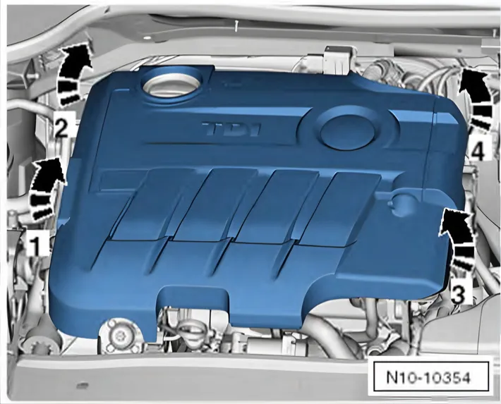
Removing
- Pull off engine cover panel -arrows-.
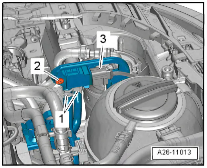
- Disconnect connector -3-.
- Unscrew bolt -2-, place pressure differential sender - G 505- to one side.
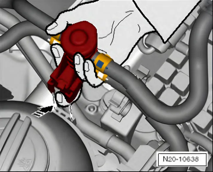
- Release fastener -arrow- and pull fuel pre-heater valve out of guide on coolant expansion tank.
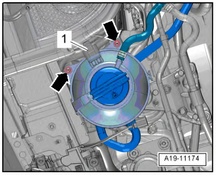
- Unscrew bolts -arrows-.
- Disconnect electrical connector -1- for coolant shortage indicator switch - F66- and push coolant expansion tank to side.
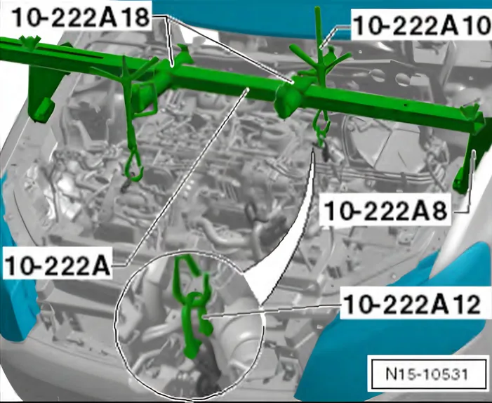
- Set up support bracket - 10 - 222 A- with relevant adapters and support engine in installation position ⇒ 2.2.4 Supporting engine in installation position, Polo.
- Attach hook of spindle - 10 - 222 A /10- to engine lifting eye.
- Pretension spindle slightly.
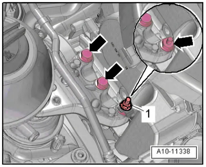
- Unscrew nut -1- and expose earth line
- Unscrew bolts -arrows-.
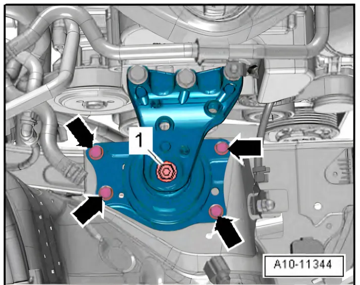
- Unscrew bolts -arrows- and remove engine mounting together with engine bracket.
Installing
Install in reverse order of removal, observing the following.
- Specified torques ⇒ 2.1.2 Assembly overview – assembly mountings, Polo.
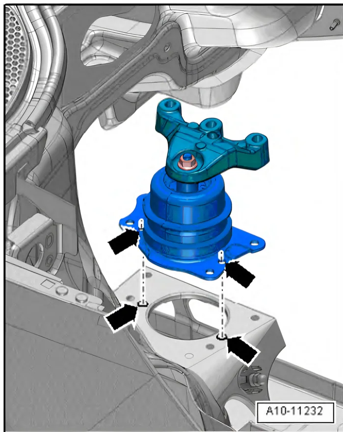
- Place assembly mounting on longitudinal member.
- The positioning holes -arrows- must be in line; check with appropriate drill if necessary.
- First screw in bolts -arrows- as far as stop by hand.
- Tighten bolts.
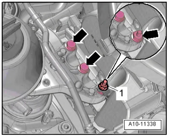
- First screw in bolts -arrows- for support arm of engine mounting as far as stop by hand.
- Make sure support arm is not twisted when bolts are tightened.
- Tighten bolts.
Tightening torques on this page
6 torques
2.1.2 Assembly overview – assembly mountings, PoloTo the drawing ↑
All items:Renew
| Item | Part | Torque | Notes |
|---|---|---|---|
| 4 | Bolt | 20 Nm +90° | |
| 6 | Nut | 40 Nm +90° | May only be unscrewed to renew engine mounting -item 3- |
| 7 | Threaded pin | 30 Nm +90° | |
| 8 | Bolt | 30 Nm +90° |
2.1.2 Assembly overview – assembly mountings, PoloTo the table ↑
| Part | Torque |
|---|---|
| 1) | 7 Nm |
| 2) | 40 Nm |