
1.6 TDI CR engine (EA189) · Removing and installing engine · Assembly mountings
Adjusting assembly mountings
- Remove engine cover panel ⇒ 3 Engine cover panel.
- Remove air filter housing.
- Remove intake hose between air mass meter - G70- and intake connecting pipe.
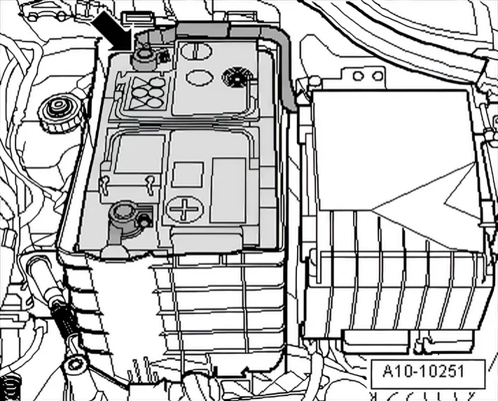
- Disconnect earth wire -arrow- from battery with ignition switched off ⇒ Electrical system; Rep. gr. 27; Battery; Disconnecting and connecting battery.
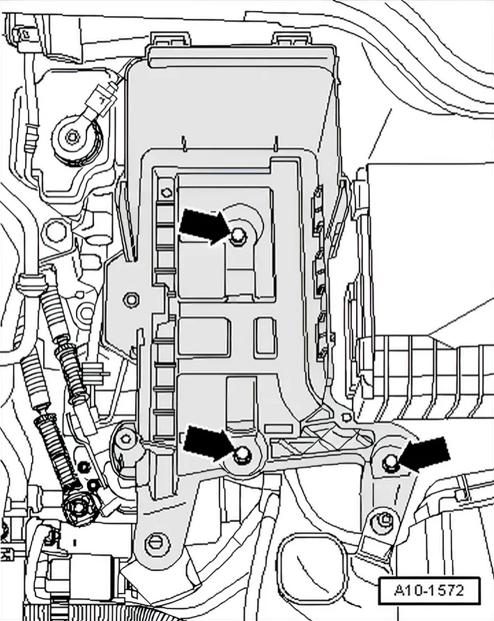
- Remove battery and battery tray -arrows-.
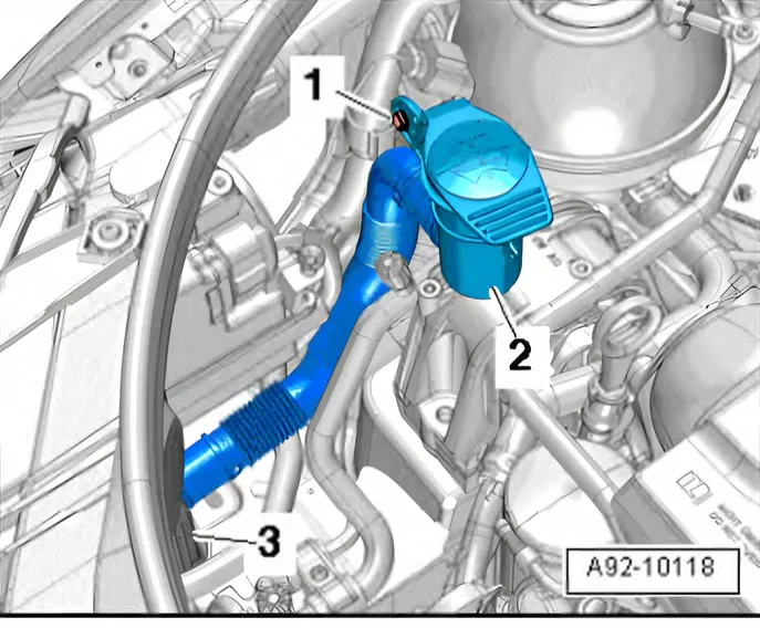
- Unscrew bolt -1-.
- Push washer fluid reservoir filler pipe with filler neck -2- to side.
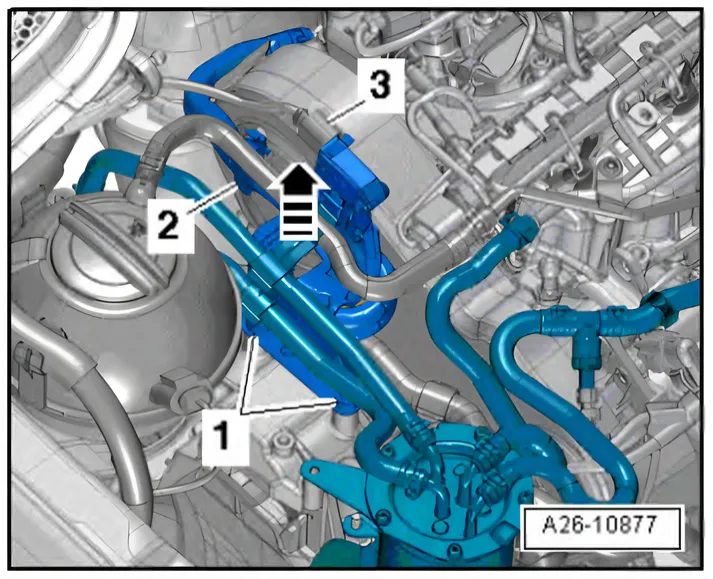
- Free air guide hose at retainer -2-.
- Pull retainer for fuel lines off upwards -arrow- and lay to side.
- Disconnect connector -3-.
- Unscrew bolts -1-, remove retainer and lay to side.
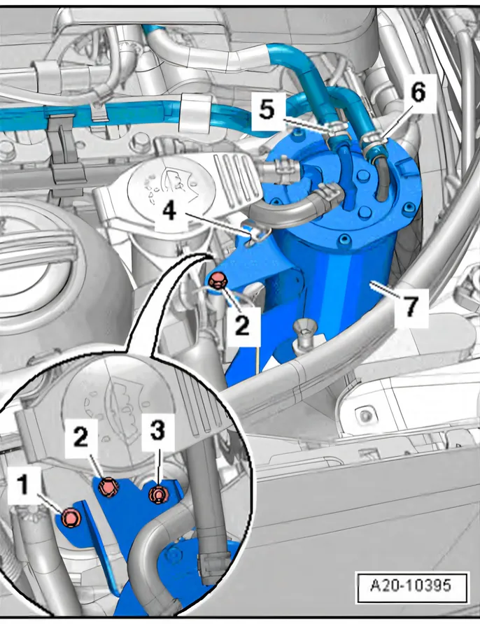
- Loosen bolt -1-.
- Unscrew bolt -2- and nut -3-.
- Take hose retainer -4- off fuel filter, place fuel filter -7- aside (fuel hoses -5- and -6- remain connected).
- Set up support bracket - 10 - 222 A- with relevant adapters as illustrated and support engine in installation position ⇒ 2.2.4 Supporting engine in installation position, Polo.
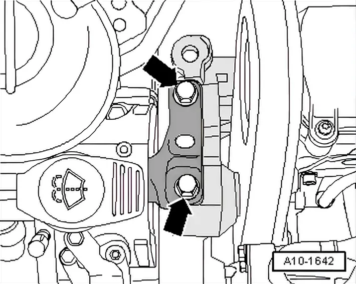
- Unscrew engine mounting bolts -arrows- in succession and renew (if not already carried out on installing engine).
- First screw bolts in loosely.
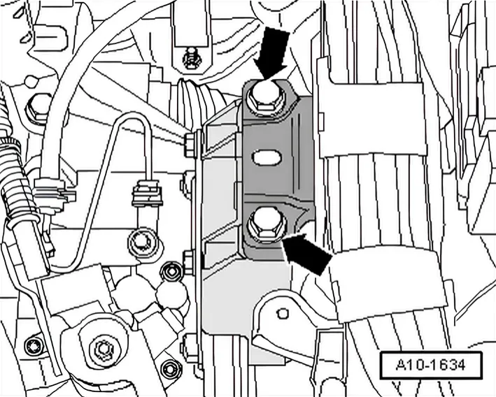
- Renew gearbox mounting bolts -arrows- in succession (if not already carried out) and screw in hand-tight.
- First screw bolts in loosely.
Engine mounting
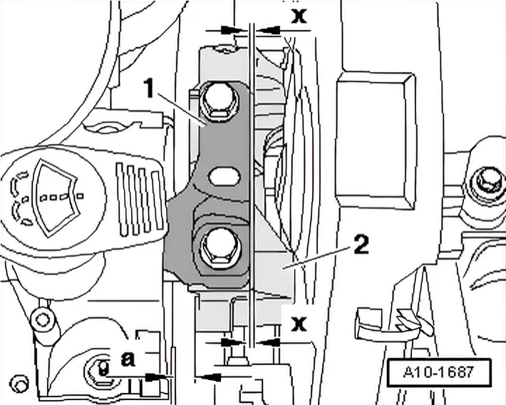
- Using an assembly lever between engine bracket and support arm -1-, adjust position of engine until the specifications listed below are obtained:
- There must be a distance of -a- = 13.5 mm between engine bracket -2- and right longitudinal member.
- The side of the engine bracket casting -2- must be aligned parallel to the support arm -1- (dimension -x- must be identical on both sides).
- Tighten bolts for engine mounting.
Gearbox mounting
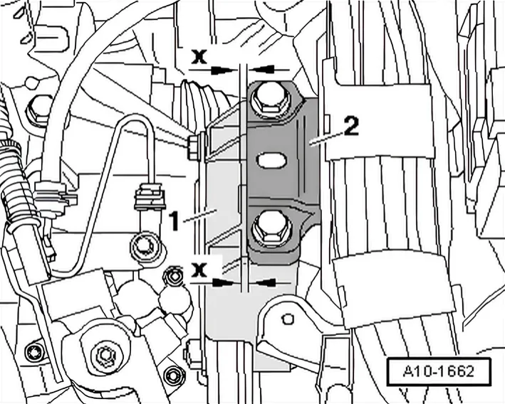
- On the gearbox side, ensure that the edges of the support arm -2- and gearbox support -1- are parallel.
- Dimension -x- must be identical on both sides of mounting.
- Tighten bolts for gearbox mounting.
- Specified torques ⇒ 2.1 Assembly overview - assembly mountings.
The remaining installation steps are carried out in the reverse sequence of removal. During this procedure, observe the following:
- Ensure that fuel lines are tight.
- Do not interchange supply line and return line (return line blue or with blue marking, supply line black).
- Observe notes after connecting battery ⇒ Electrical system; Rep. gr. 27; Battery; Disconnecting and connecting battery.