
7-speed DSG gearbox 0AM (DQ200) · Controls, Housing · DSG Transmission Mechatronic J743
DSG Transmission Mechatronic J743, Removing with Transmission Installed
- Bring the DSG Transmission Mechatronic - J743- into the »removal position« by hand. Refer to ⇒ 3.4 DSG Transmission Mechatronic J743, Moving into Removal Position by Hand.
Special tools and workshop equipment required
- Assembly Lever - Mechatronic - T10407-
- Used Oil Collection and Extraction Unit - SMN372500-
- Engine Bung Set - VAS6122-, or Cap - 0AM 325 120 A-
- Vehicle Diagnostic Tester
Brief Description
The must be enough available space in front of the transmission in order to remove the Mechatronic. Depending on the vehicle, it is necessary to remove components that do not have anything to do directly with the transmission. The air filter housing for example, and if equipped, the charge air hoses or coolant hoses.
If there are any brackets on the Mechatronic cover, these must also be removed.
The Mechatronic is brought into the removal position using the Vehicle Diagnostic Tester. All gear positions are »driven into neutral«.
In this position, insert the Assembly Lever - Mechatronic - T10407- between the engaging lever and transmission housing. Now it is possible to relieve the Mechatronic plunger and remove it by hand from the engaging lever sockets.
The Mechatronic can be removed and installed. Make sure the clutch plunger is in the correct position in the engaging lever socket during installation.
The following description must therefore be followed step by step.
Removing
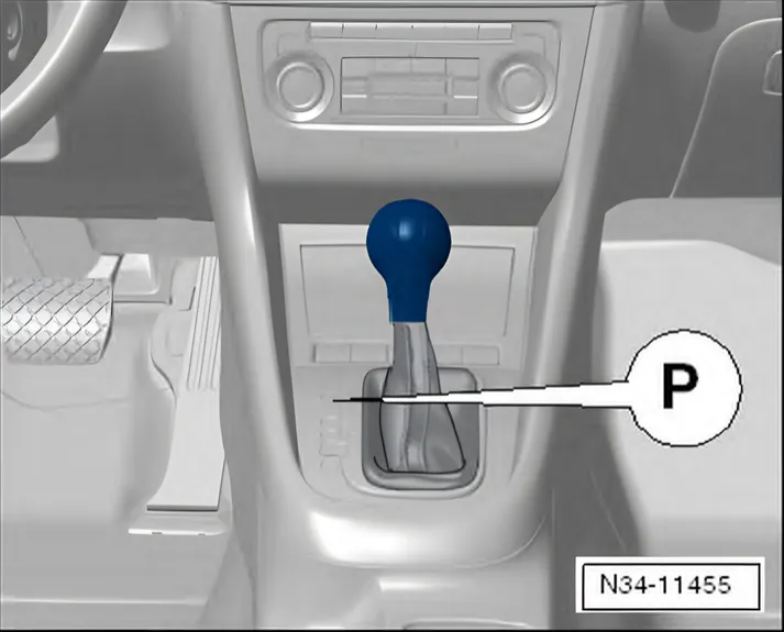
- Move the selector lever into »P«.
- Lift the vehicle, all four take-up points of lifting platform at the same height.
- Remove the noise insulation. Refer to ⇒ Body Exterior; Rep. Gr. 50; Noise Insulation.
- Connect the Vehicle Diagnostic Tester and then select “7- Speed DSG® transmission” Move into -Neutral- gear under Guided Functions.
- Switch the ignition off.
- Raise the vehicle.
- Remove the air filter housing:
- Gasoline engine. Refer to ⇒ Rep. Gr. 24; Air Filter; Overview - Air Filter Housing.
- TDI engine. Refer to ⇒ Rep. Gr. 23; Diesel Direct Injection System; Overview - Air Filter.
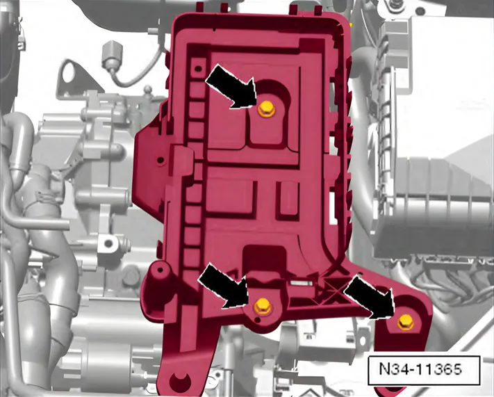
- Remove the battery and the battery tray. Refer to ⇒ Electrical Equipment; Rep. Gr. 27; Battery; Battery, Removing and Installing.
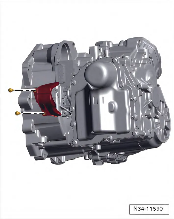
Some Vehicles have A Cover Over the Engaging Levers.
The cover prevents dirt from getting in.
Tightening specification: 8 Nm.
- Remove this cover if equipped.
- Remove the starter. Refer to ⇒ Electrical Equipment; Rep. Gr. 27; Starter; Starter, Removing and Installing.
- To discharge any static electricity, touch vehicle ground with hand (without wearing a glove). Refer to ⇒ 7.2 Transmission.
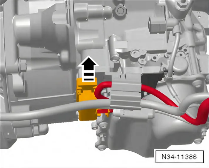
- Release the connector lock on the Mechatronic by pulling in the direction of the -arrow- and remove the connector.
- Place the Used Oil Collection and Extraction Unit - SMN372500- or Drip Tray under the transmission.
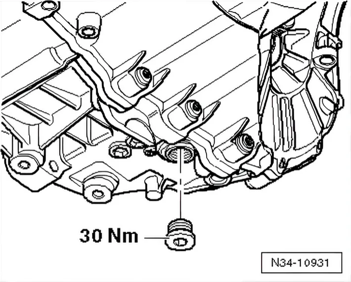
- Drain the transmission fluid then reattach the oil drain plug.
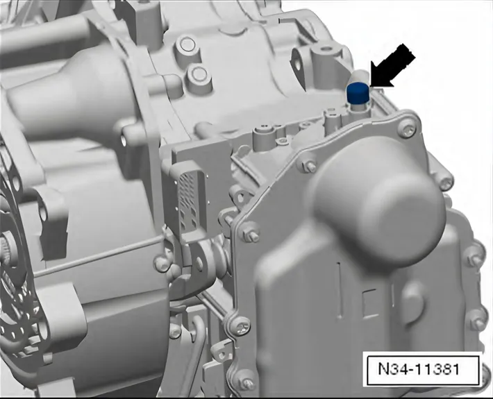
- Remove the cap -arrow- from the Mechatronic vent. Seal so that it is oil-tight using a clean plug taken from Engine Bung Set - VAS6122-. Use the Protective Cap - 0AM 325 120 A- if available.
Checking the hydraulic fluid level for the Mechatronic is not possible. The Mechatronic vent must be sealed oil-tight before performing any assembly work.
Fluid that has leaked out of the Mechatronic hydraulic area may not be refilled or checked. Replace the Mechatronic if fluid is leaking.
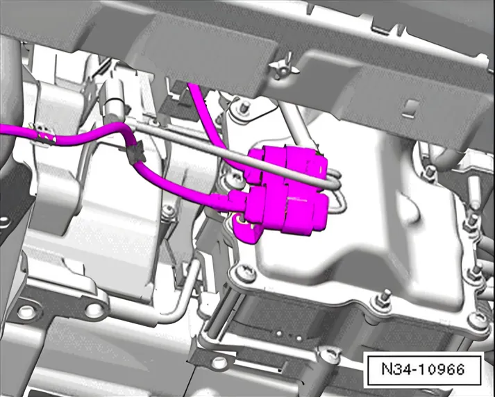
- Remove all of the front brackets from the transmission.
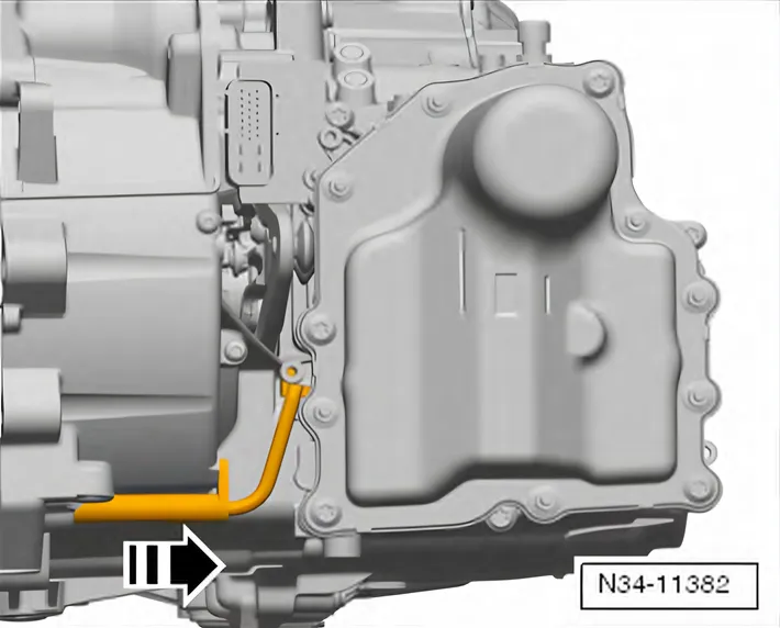
- Carefully remove the Transmission Input Speed Sensor 3 - G641- from the housing in the direction of the -arrow- using a screwdriver.
A »Difficult« Procedure Occurs in the Following:
Now both dual clutch engaging levers must be »pushed away« from the Mechatronic plungers. Otherwise the levers will jam the Mechatronic at the plungers and then the Mechatronic cannot be removed.
- Please also read this description once through all the way to the end. This will help to do the following steps »correctly«.
Both levers must now be carefully pulled out from the plungers.
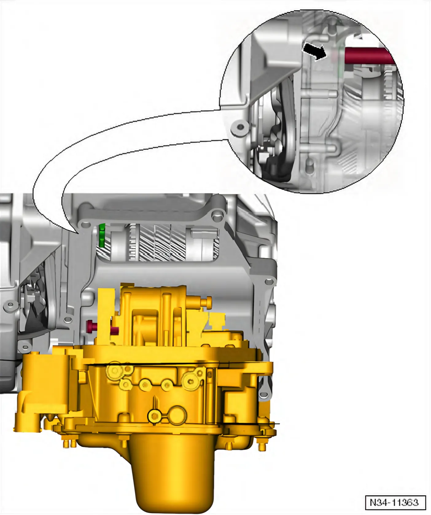
- Please look at the -maroon- engaging lever in this image.
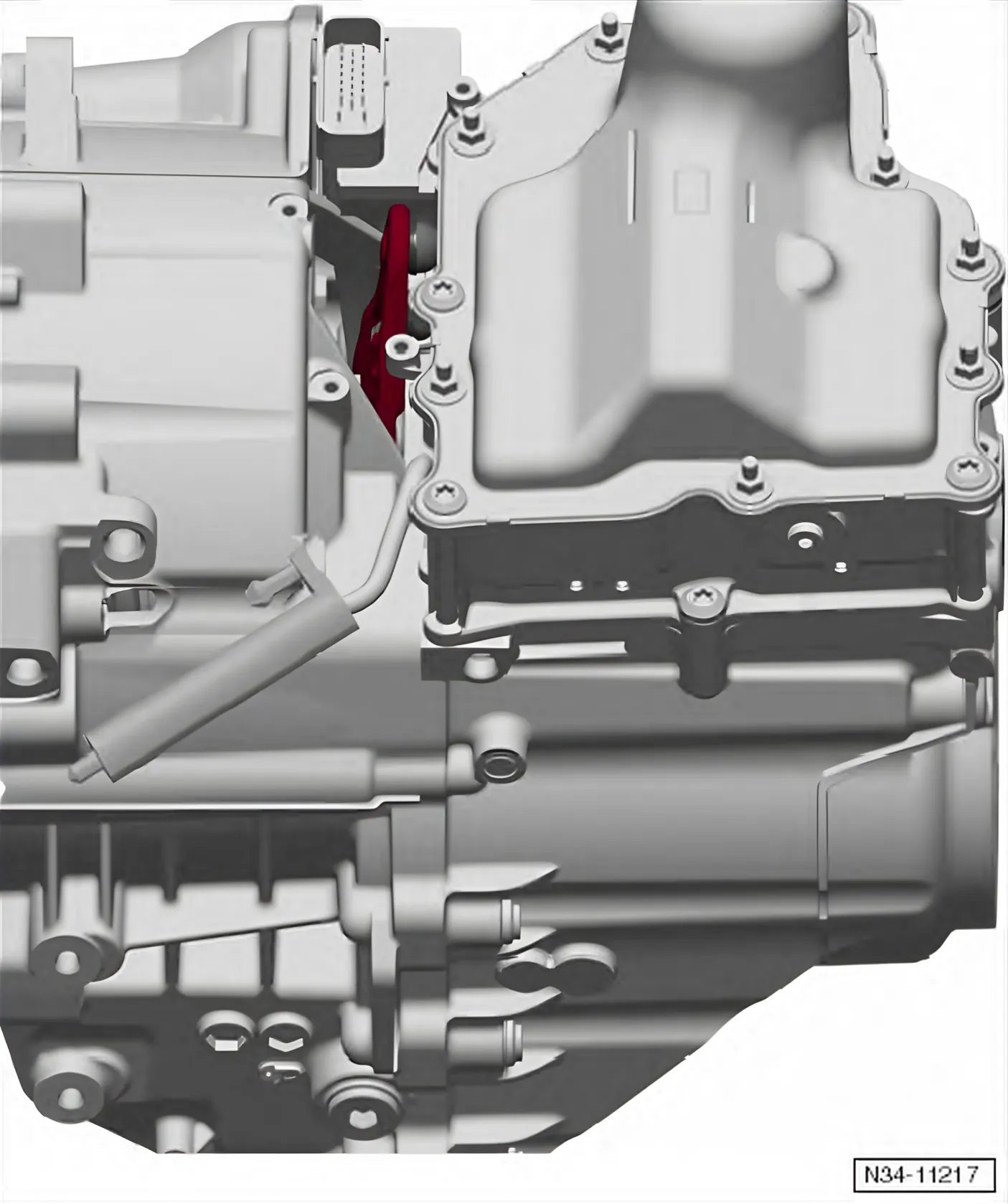
- Insert the Assembly Lever - Mechatronic - T10407- to the right of this.
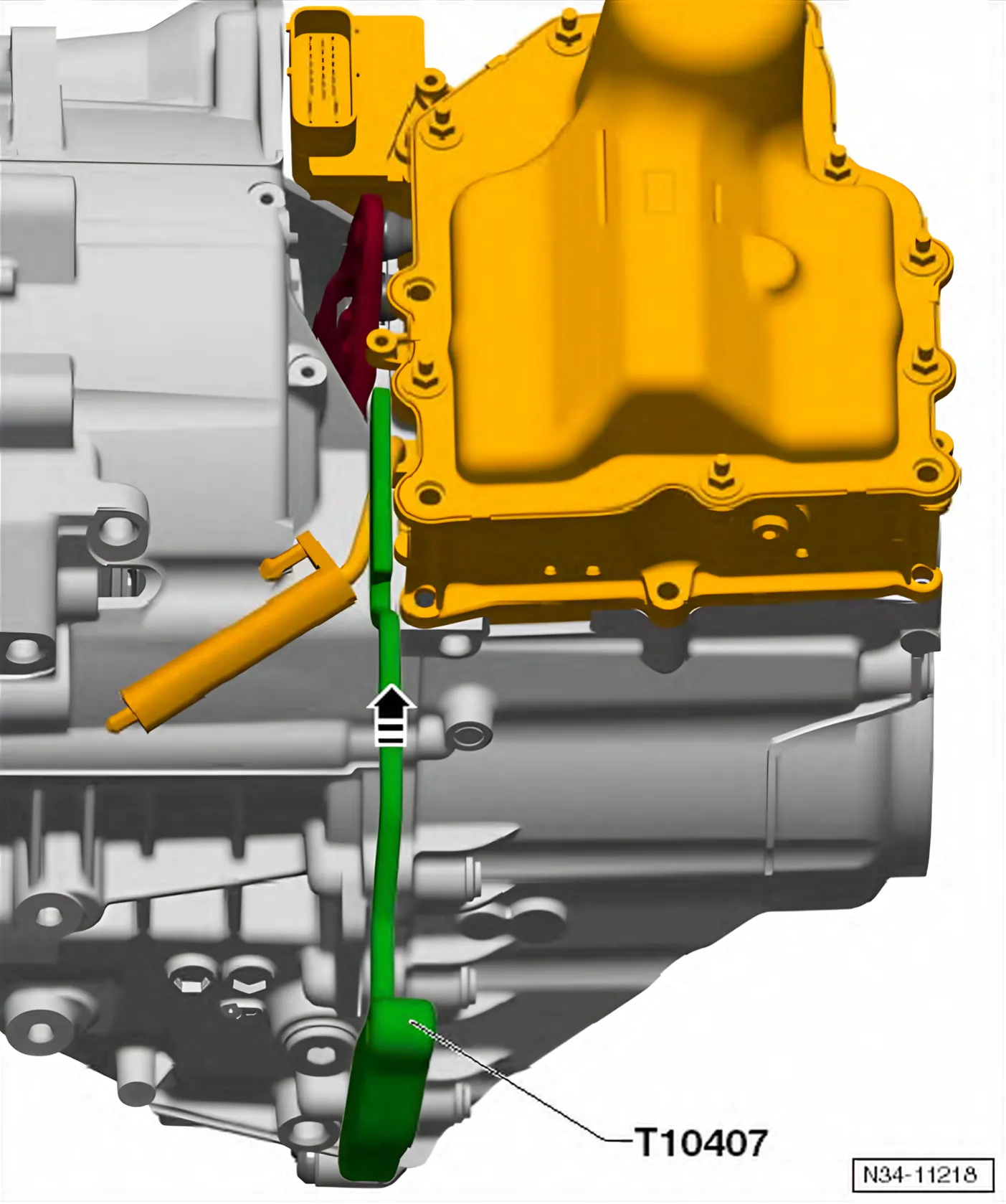
- Insert until the groove aligns with the housing rib -arrow-.
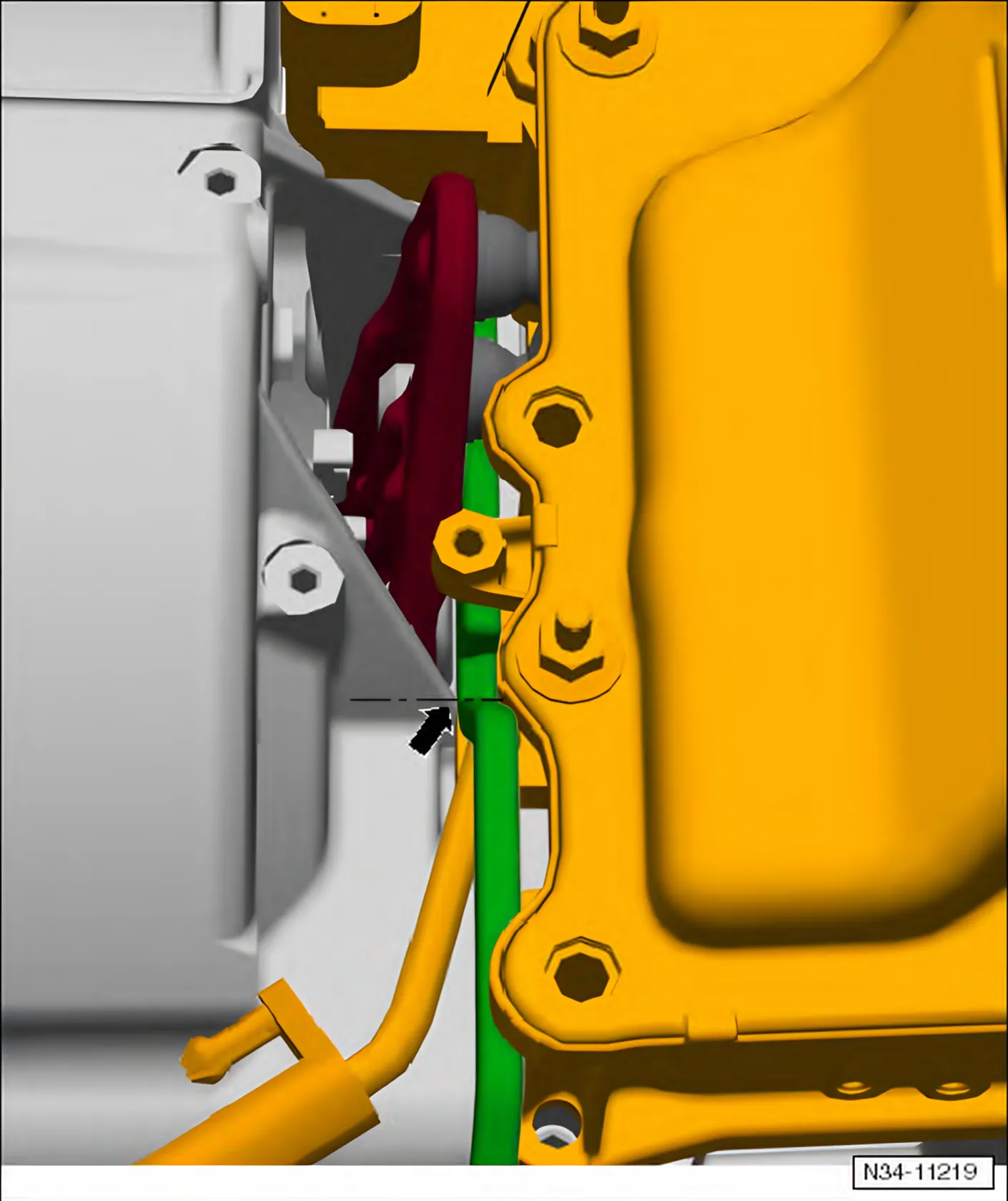
Do not go further.
- The »rear side« of the Assembly Lever - Mechatronic - T10407- should rest completely on the transmission housing.
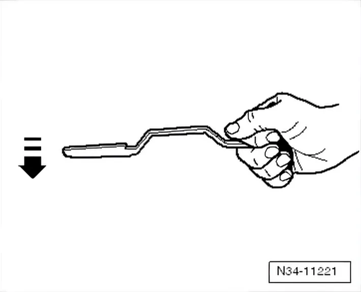
This prevents the handle from sliding out when turning it.
Turn the Assembly Lever - Mechatronic - T10407- counter-clockwise. Then press the engaging lever away from the plungers direction of the -arrow-.
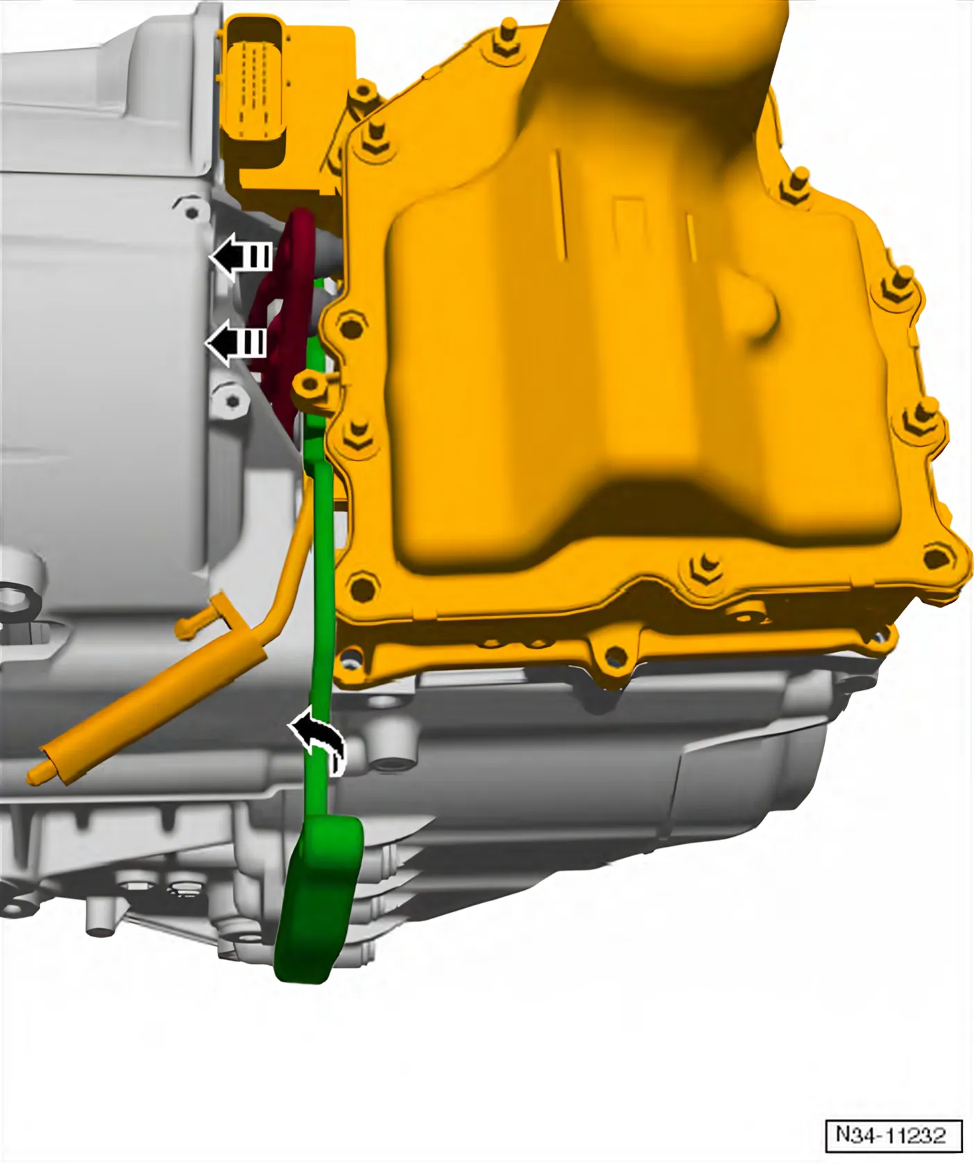
Do not remove the Assembly Lever - Mechatronic - T10407-. It must stay inserted between the engaging lever and the transmission housing for the entire procedure.
- If necessary, push the Assembly Lever - Mechatronic - T10407- against the transmission using a screwdriver.
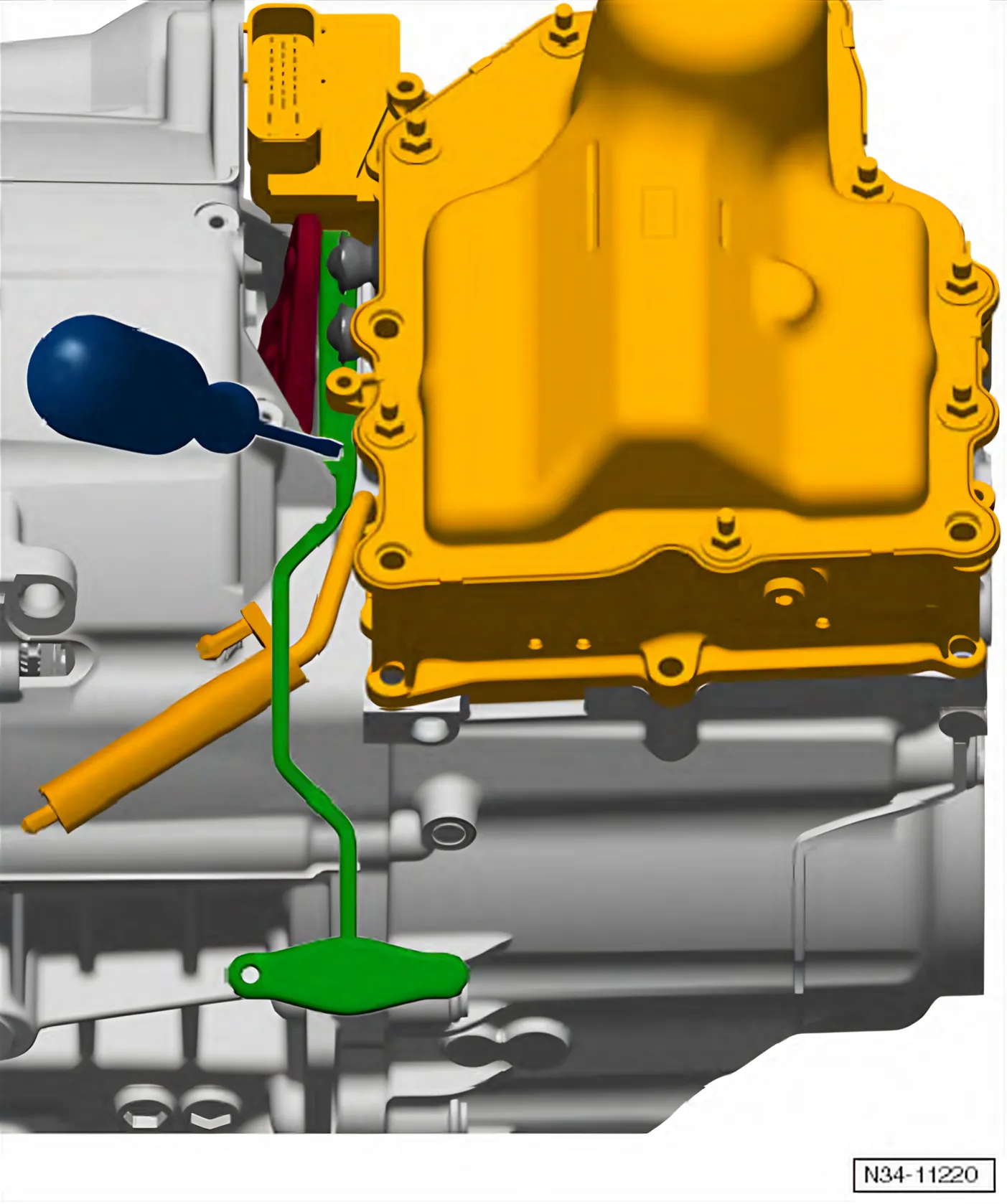
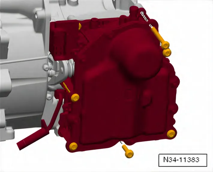
- Remove the DSG Transmission Mechatronic - J743- bolts »in a diagonal sequence«.
»There are 4 long and three short bolts.«
Do Not Remove More than 7 Bolts.
- Pay attention to exactly which bolts are removed. Do not remove any bolts from the cover.
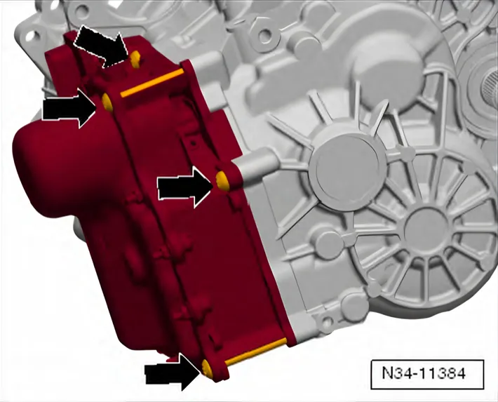
For clarity, the transmission is shown here again from the side.
The Mechatronic must be removed. The cover should not be removed.
Therefore Do Not Remove More Than 7 Bolts.
- To discharge any static electricity, touch vehicle ground with hand (without wearing a glove). Refer to ⇒ 7.2 Transmission.
- Remove the Mechatronic.
- Make sure that no fluid comes out of the vent.
If the Mechatronic »gets stuck« and Cannot Be Removed
It may not be possible to remove the Mechatronic. In this case, the gear selector is »caught« at the »upper left side« on the transmission housing.
In this situation, the Mechatronic must not be removed with strong force.
- Place the Mechatronic back on the transmission housing and secure the Mechatronic with a screw.
- Move the Mechatronic by hand into the »Removal position«. Refer to ⇒ 3.4 DSG Transmission Mechatronic J743, Moving into Removal Position by Hand.
Install the Mechatronic. Refer to ⇒ 3.5 DSG Transmission Mechatronic J743, Installing.
Tightening torques on this page
1 torque
In the steps
| Step | Torque |
|---|---|
| Tightening specification: 8 Nm. | 8 Nm |