
SSP 442 The 1.6ltr. TDI Engine with Common Rail Injection System
Rail and injectors
High-pressure accumulator (rail)
The rail is a high-pressure accumulator for the fuel that is delivered by the high-pressure pump. It supplies the injectors with the quantity of fuel required for all operating modes.
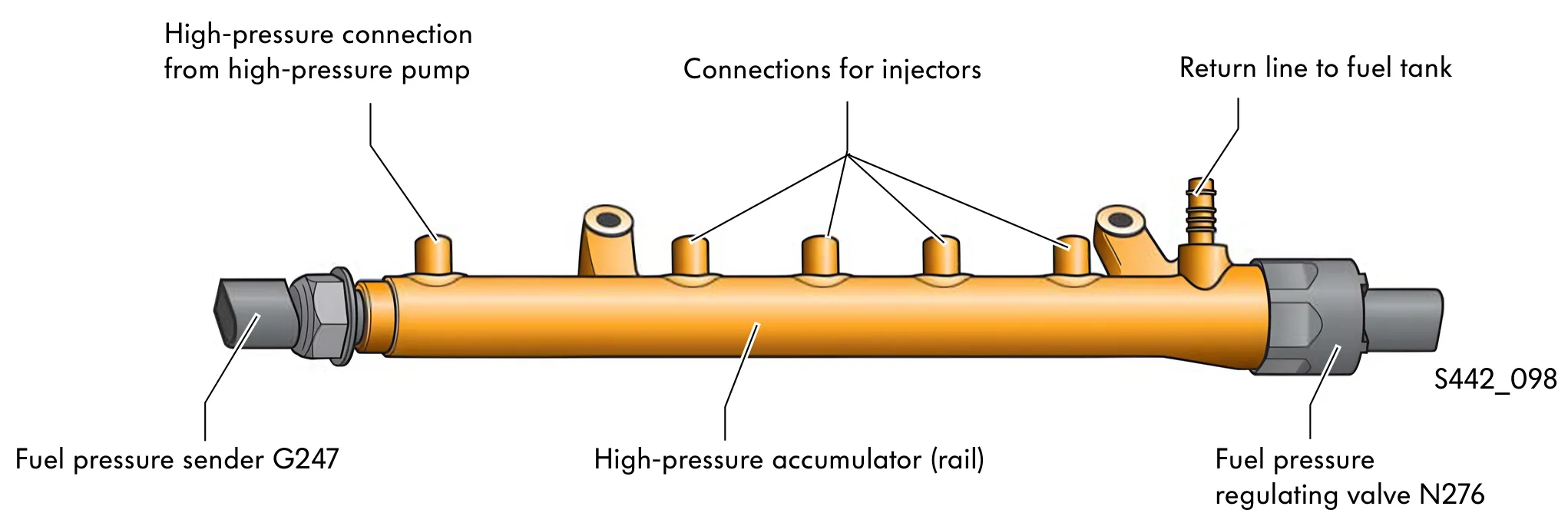
Fuel pressure sender G247
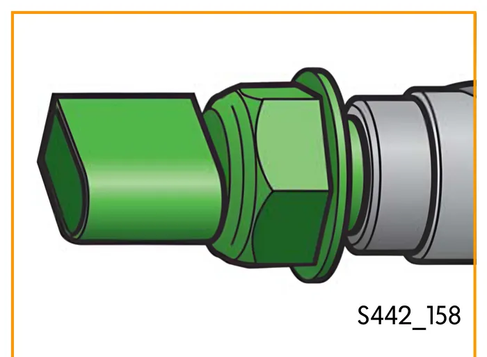
The fuel pressure sender G247 measures the fuel pressure in the rail. The pressure is converted into a voltage signal that is evaluated by the engine control unit.
Based on the maps stored in the engine control unit, the pressure signal is used to calculate the activation period of the injectors and the high-pressure regulation by the fuel metering valve.
The fuel pressure sender is bolted directly onto the high-pressure accumulator.
Effects upon failure
If the signal fails or there is an implausible signal from the sender, the engine control unit switches to emergency-running mode. The engine power is reduced and the maximum engine speed limited to 3000 rpm.
Fuel pressure regulating valve N276
The fuel pressure regulating valve is located on the high-pressure accumulator (rail). It regulates the fuel pressure in the high-pressure accumulator. The engine control unit uses a pulse-width modulated signal to operate the valve.
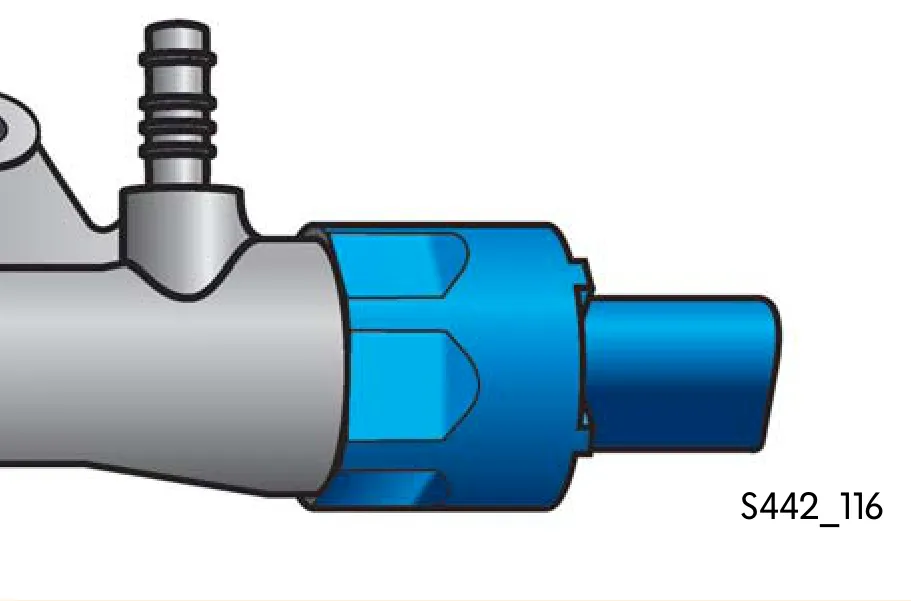
Design
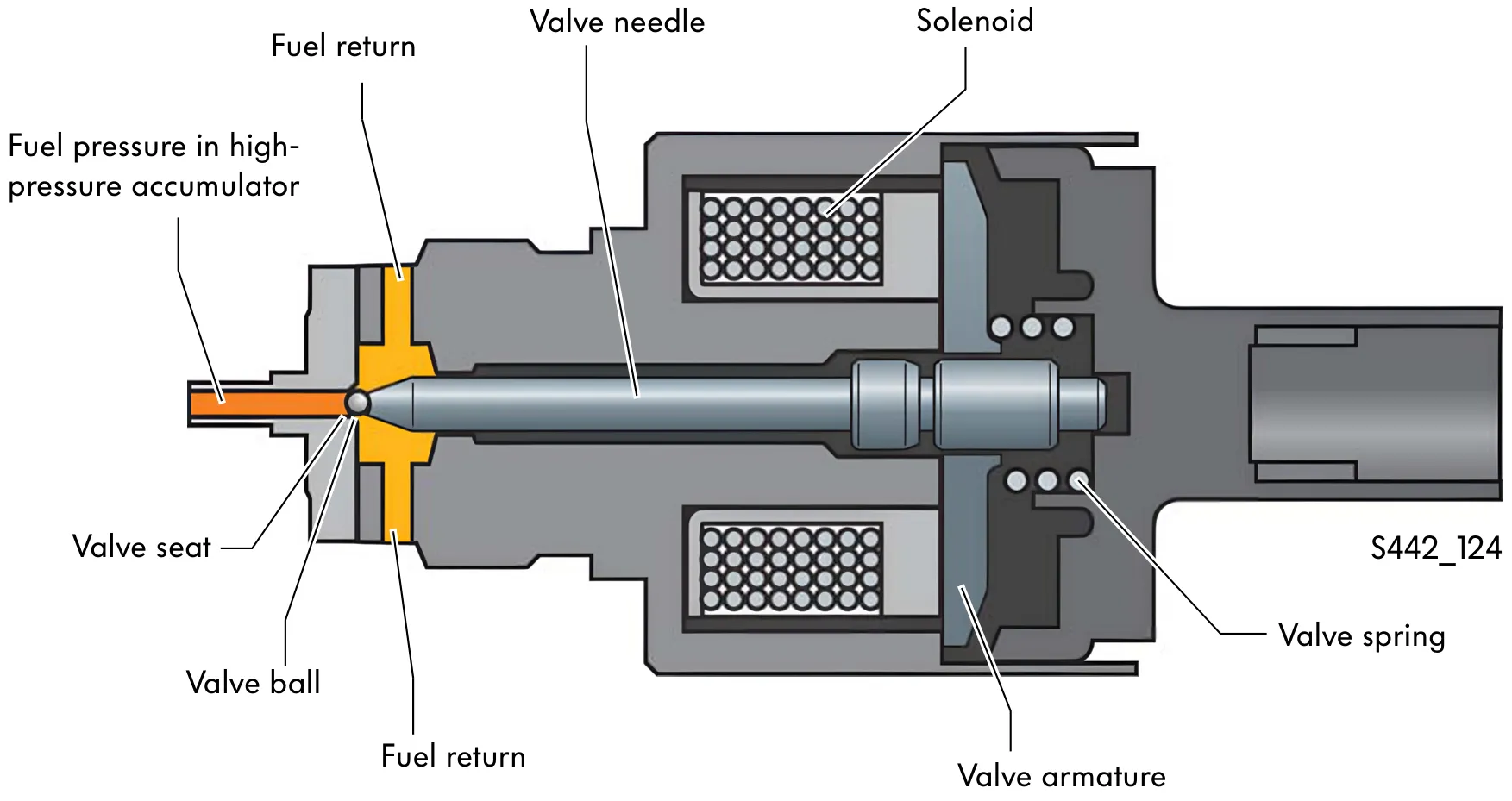
Function
Regulating valve not activated
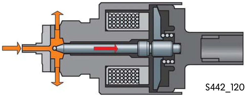
Upon “Engine OFF”, the valve ball is pressed into the valve seat only by the spring force. This maintains a low fuel pressure. If the fuel pressure in the high-pressure accumulator is greater than the spring force, the valve opens and fuel flows to the fuel tank via the fuel return.
Regulating valve activated
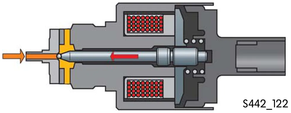
The engine control unit adjusts the operating pressure in the high-pressure accumulator by operating the solenoid with a pulse-width modulated signal. The valve armature is energised and presses the valve needle into its seat. The quantity flowing into the fuel return line is varied in relation to the duty cycle.
Effects upon failure
The engine will not run if the fuel pressure regulating valve fails. The fuel pressure required for injection cannot be built up.
Injectors
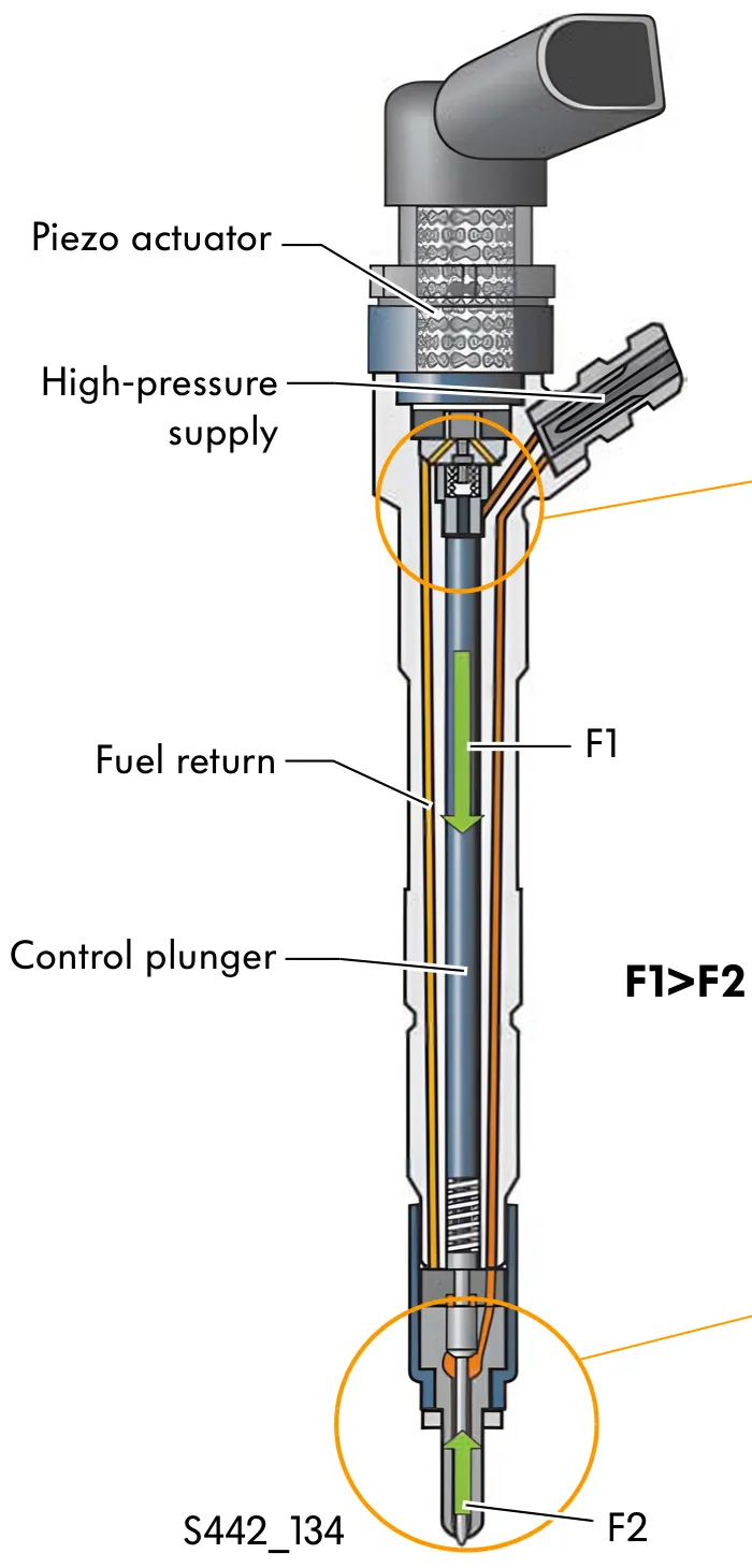
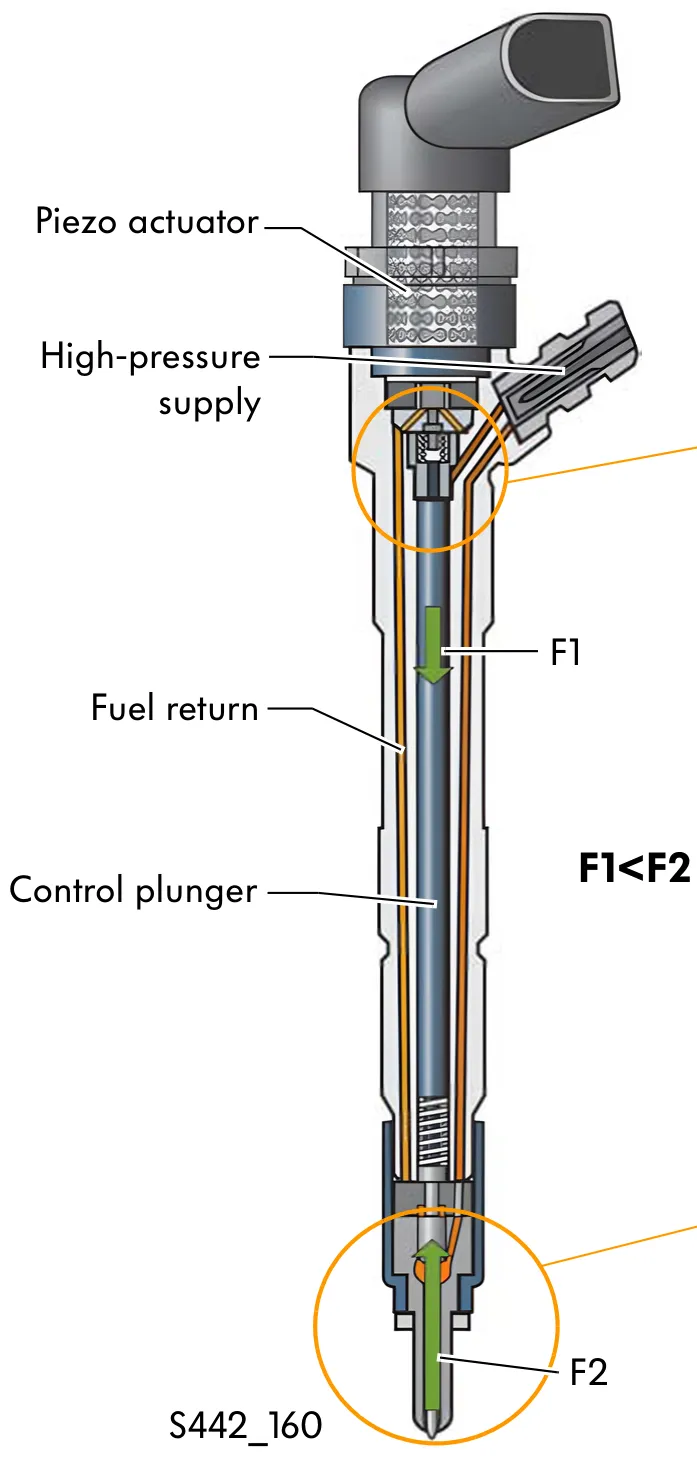
The (piezo) injectors, which are connected to the rail via a high-pressure line, inject the quantity of fuel required for all engine operating modes into the combustion chambers. The respective injection quantity is made up of a pilot injection quantity, a main injection quantity and a secondary injection quantity. The injectors are controlled by a piezo actuator. This results in very short switching times, map-controlled injection quantities and a “smoother” combustion process.
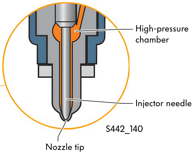
Injector (piezo actuator) not activated
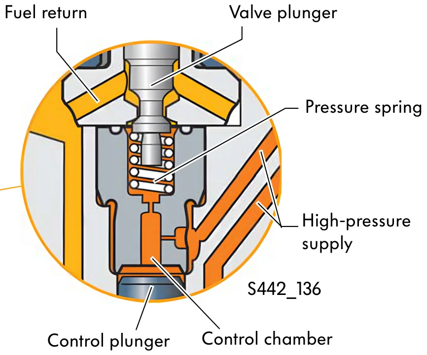
The fuel reaches the control chamber and the highpressure chamber of the injector via the high-pressure supply line. The force (F1) acting on the control plunger is greater than the force (F2) acting on the nozzle needle.
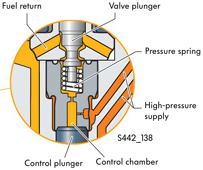
The nozzle is closed. The pressure spring closes the return with the valve plunger to prevent the fuel flowing out when the engine is not turning over.
Injector (piezo actuator) activated
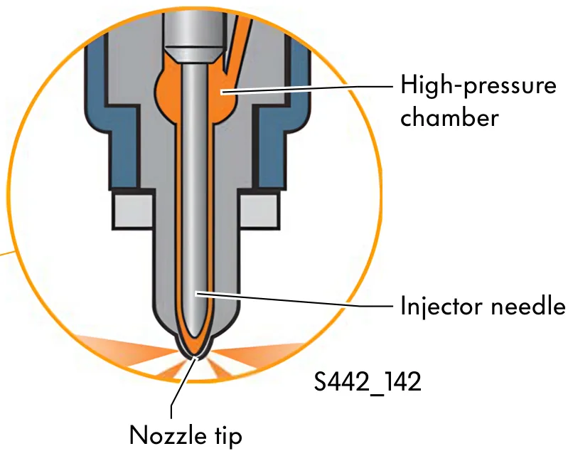
The piezo actuator in the injector is activated and expands. The valve plunger is pushed against the spring force and connects the control chamber to the fuel return. This reduces the pressure in the control chamber.
The hydraulic force (F2) at the nozzle needle is now greater than the force (F1) applied by the control plunger. The nozzle needle moves upwards and the fuel is injected into the combustion chamber.
Identification of injectors
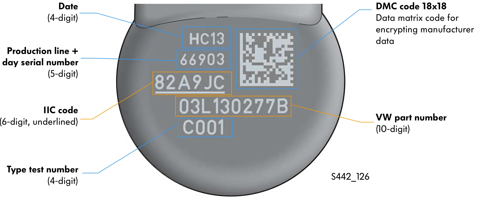
There is a data carrier on the top of the injectors. In addition to the VW parts number, date and type test number, the 6-digit IIC code (Injector Individual Correction) is stamped there.
The IIC code needs to be entered in the Guided Function “Read/adapt correction values for injectors” when the injectors are replaced.
Engine control unit
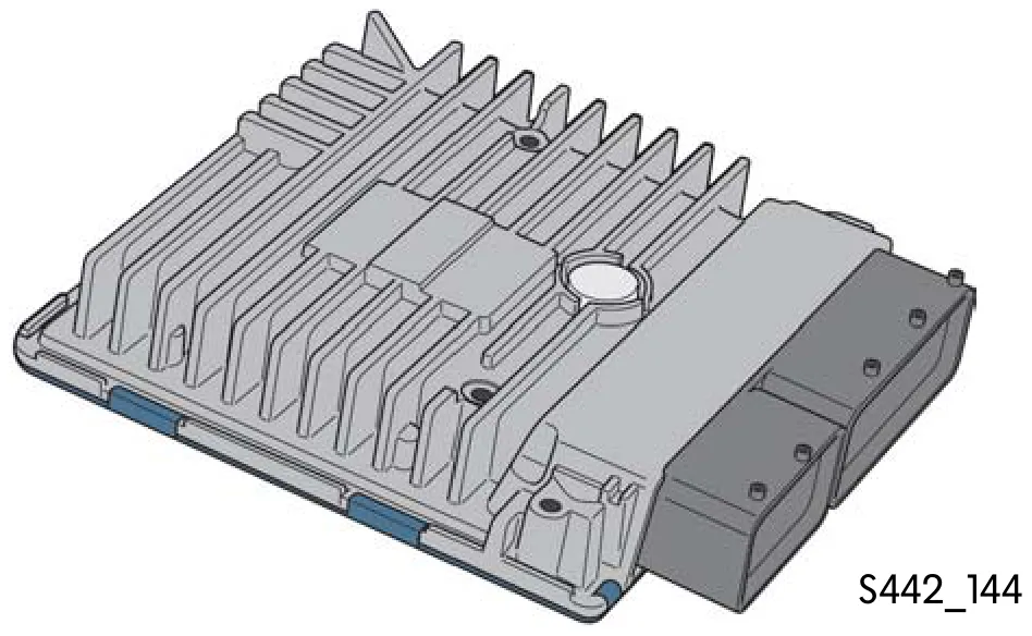
The engine control unit checks all processes that are required to regulate the engine system.
The engine control unit regulates the engine output data, like fuel injection quantity, fuel injection time etc. using the vehicle data it receives (engine speed, coolant temperature, accelerator pedal position etc.).
Combination valve
In the Polo 2010, the combination valve is mounted near the fuel filter. The combination valve has the task of preheating the fuel.
Function
Combination valve closed
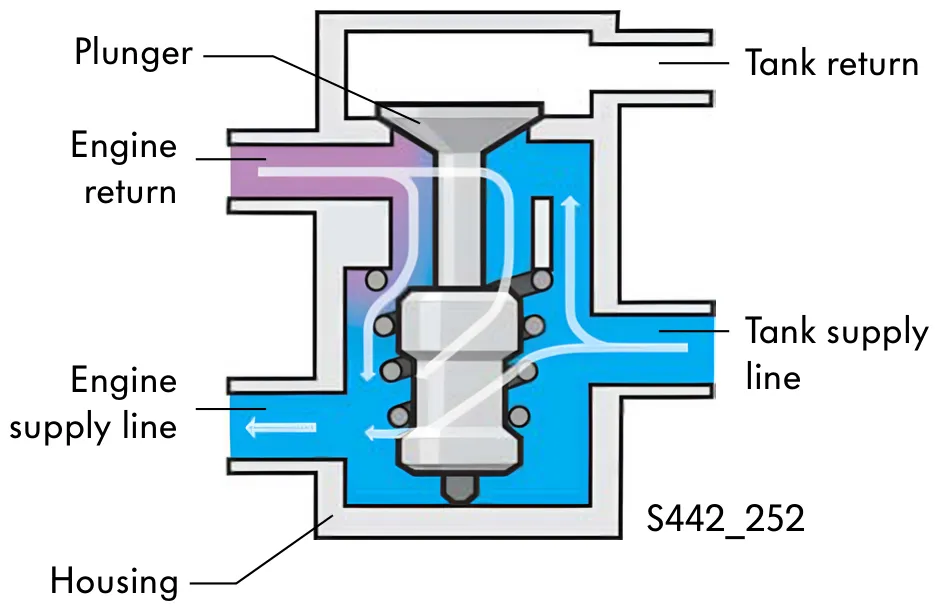
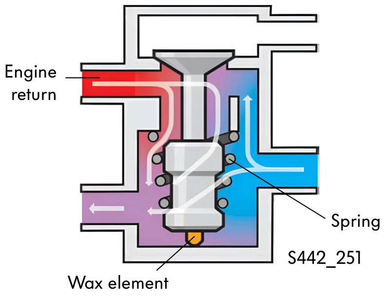
When cold starting, the return to the tank is closed by the plunger in the combination valve. Warm fuel from the engine return is mixed with cold fuel from the tank in the combination valve and is delivered to the engine again. Preheating the fuel in this way prevents the separation of paraffin and thus fuel filter blockages.
As the engine temperature rises, the fuel temperature in the engine return line also rises. As a result, the plunger heats up together with the wax thermostatic element in the combination valve. The wax thermostatic element expands and presses the plunger upwards against the spring force.
Combination valve open
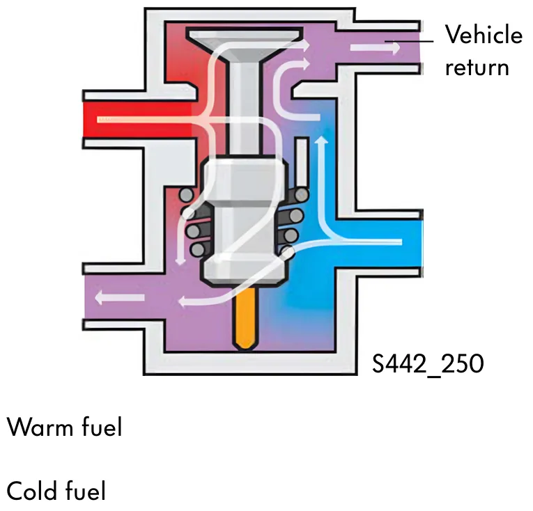
Once the operating temperature has been reached, the combination valve opens the return line to the tank. Cold fuel from the tank mixes with warm fuel from the engine return line and flows back into the fuel tank. This allows the fuel in the fuel tank to warm up at low temperatures.