SSP 094 Diagnosis of the automatic gearboxes 0AM and 02E
Measured value blocks of the gearbox 0AM
Selected measured value blocks of the gearbox electronics serve to carry out a correct fault diagnosis on the automatic gearboxes DSG.Therefore, if a fault is detected on the automatic gearbox, a printout of all the measured value blocks must be sent (at idle speed, if the vehicle is stationary or in P, N or D mode) The following information can be read in the measured value blocks (MVB):
- Identification of the software and hardware level of the automatic gearbox control unit
- current operating values (oil pressure values in the mechatronics, positions of the individual gear adjusters, clutch status, speeds of the individual shafts, selector lever position, etc.)
- the current values recorded during the operation (journey time in the individual driving modes, operating temperatures of the clutches, journey time in all operating temperatures and warnings, etc.
- specific environmental conditions when the last two faults occured
Description of the operating mode for actuating the automatic gearbox
- The mechatronics controls the individual gearbox parts by means of its actuators. It comprises two actuation elements, each operating the corresponding clutch K1 or K2 independently. Furthermore, it comprises four actuation elements for changing the gears (1+3, 2+4, 5+7, 6+R). The positions of all the actuation elements can be checked using the measured value blocks (MVB).
- It is important that the mechatronics is supplied with pressure oil in order to ensure its proper operation. Insufficient pressure can cause a jolt or a complete loss of function of the automatic gearbox. The current pressure can be checked in the MVB 30.3.
- The mechatronics alters the contact pressure exerted on the corresponding clutch depending on the transmitted torque – thus, the clutch is not permanently under continuous pressure, yet it changes while driving.
- The state of the clutch K1 can be determined by reading the MVB 95-97, whereas the state of the clutch K2 can be determined by reading the MVB 115-117. It is possible to determine the current position of the adjuster for K1 in the MVB 91 and for K2, in the MVB 111.
- The MVB 235-244 store the environmental conditions at the last fault entry, the MVB 245-254 store the environmental conditions at the entry of the second last fault.
Important measured value blocks
Measured value blocks
| Nbr. | Description | Value example |
|---|---|---|
| 4.1 | Position of the selector lever (E313) | P (R, N, D, S, T+, T-) |
| 5.1 | Gearbox input speed (sender G641 / G182, i. e. in front of the clutches) | 766/rpm |
| 5.2 | Engine speed (CAN value) | 766/rpm |
| 5.3 | Input shaft speed 1 (sender G632 – behind the clutch K1) | 0/rpm |
| 5.4 | Input shaft speed 2 (sender G612 – behind the clutch K2) | 0/rpm |
| 80.1 | Manufacturing date of the mechatronics | TFK-535 05. 07.11 |
| 30.1 | Max. permitted pressure in the mechatronics (S1 max.) | 60.00 bar |
| 30.2 | Min. permitted pressure (S4 min.) | 42.00 bar |
| 30.3 | Actual pressure value (V401) | 30.34 bar (example of an incorrect/low value) |
Current position of the actuation elements of the clutches (when the vehicle is stationary in P mode):
Measured value blocks: Current position of the actuation elements of the clutches – Example of the values in P
| Nbr. | Description | Value example |
|---|---|---|
| 91.1 | Desired position of the adjuster for K1 | 0.0 mm |
| 91.2 | Actual value of the adjuster for K1 | 2.1 mm |
| 111.1 | Desired position of the adjuster for K2 | 0.0 mm |
| 111.2 | Actual value of the adjuster for K2 | 2.3 mm |
While driving it is almost impossible to distinguish between the nominal or the actual value, only when the vehicle is stationary in the P or N mode is the actual position of the adjuster slightly higher than when in the desired position.
Clutch characteristic curve
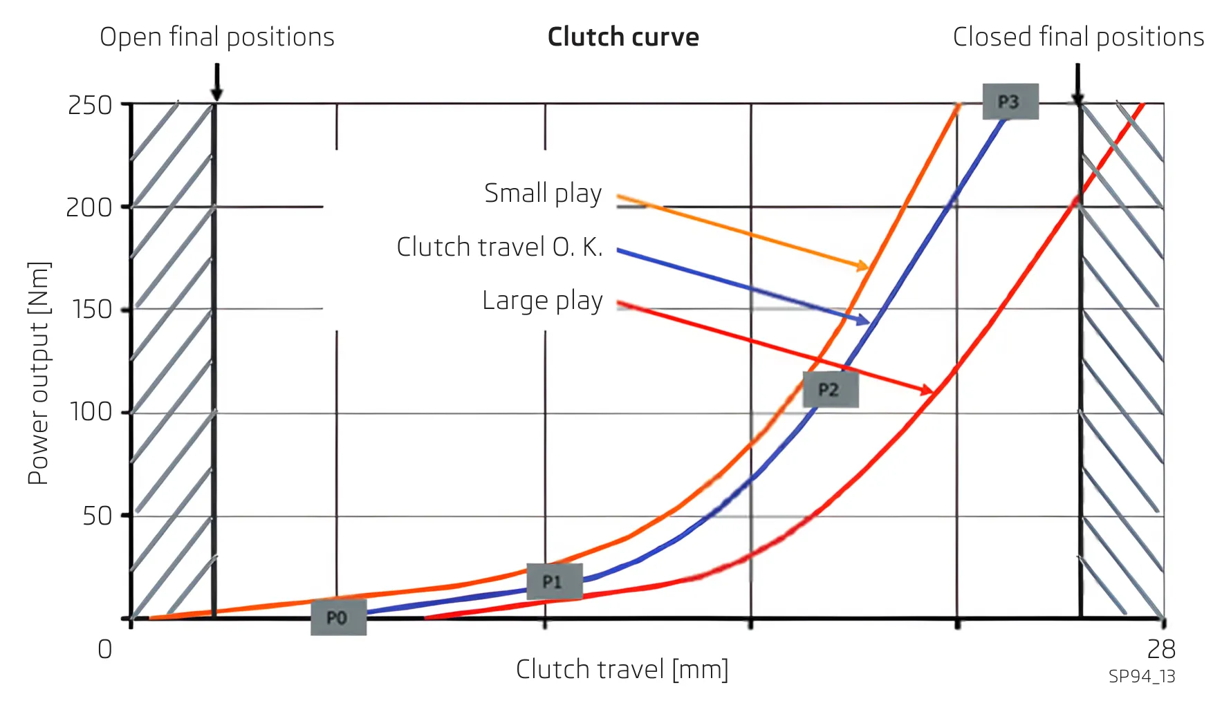
Blue curve: The characteristics of the clutch are O. K.
Red curve: The clutch closes already at 200 Nm, however it should transmit a torque of up to 250 Nm.
The customer complains about weak engine power, the vehicle can also jolt.
Yellow curve: The clutch is engaged, which can be determined from the measured value blocks 5. 3 and 5. 4.
State of the play and wear of K1 in the measured value blocks
Measured value blocks – State of play and wear of clutch K1
| Nbr. | Description | Example No. 1 | Example No. 2 | Example No. 3 |
|---|---|---|---|---|
| 95.1 | Changes to the position 0 | 9.0 mm | 3.0 mm | 12.0 mm |
| 95.2 | Torque for the position 0 | 0.0 Nm | 0.0 Nm | 0.0 Nm |
| 95.3 | Changes to the position 1 | 11.7 mm | 6.7 mm | 14.7 mm |
| 95.4 | Torque for the position 1 | 16.0 Nm | 16.0 Nm | 16.0 Nm |
| 96.1 | Changes to the position 2 | 18.2 mm | 14.2 mm | 22.0 mm |
| 96.2 | Torque for the position 2 | 153.4 Nm | 153.4 Nm | 153.4 Nm |
| 96.3 | Changes to the position 3 | 21.6 mm | 20.3 mm | 26.3 mm |
| 96.4 | Torque for the position 3 | 249.9 Nm | 249.9 Nm | 193.3 Nm |
| 97.1 | Clutch K1 – Final position in the open position | 2.4 mm | 2.4 mm | 2.4 mm |
| 97.2 | Clutch K1 – Final position in the closed position | 27.4 mm | 27.4 mm | 27.4 mm |
95.1 minus 97.1 must be greater than 2 mm,
Due to insufficient clutch play, shifting of the input shaft occurs. (This will be entered in the fault memory.) See example No. 2 and a low difference in value of the blocks 95.1 minus 97.1.
97.2 minus 96.3 must be greater than 1 mm,
At a lower value the maximum torque is not transmitted and a clutch slippage occurs. The vehicle may start to jolt when driving in higher gears or when accelerating. (This will be entered in the fault memory.) See example No. 3 and a low difference in value of the blocks 97.2 minus 96.3 (subsequently a low torque is transmitted and entered in block 96.4.).
State of the play and wear of K2 in the measured value blocks
Measured value blocks – State of play and wear of clutch K2
| Nbr. | Description | Example No. 1 | Example No. 2 | Example No. 3 |
|---|---|---|---|---|
| 115.1 | Changes to the position 0 | 8.3 mm | 3.1 mm | 12.0 mm |
| 115.2 | Torque for the position 0 | 0.0 Nm | 0.0 Nm | 0.0 Nm |
| 115.3 | Changes to the position 1 | 10.4 mm | 6.7 mm | 14.7 mm |
| 115.4 | Torque for the position 1 | 16.0 Nm | 16.0 Nm | 16.0 Nm |
| 116.1 | Changes to the position 2 | 17.4 mm | 14.2 mm | 22.0 mm |
| 116.2 | Torque for the position 2 | 153.4 Nm | 153.4 Nm | 153.4 Nm |
| 116.3 | Changes to the position 3 | 21.6 mm | 20.3 mm | 26.3 mm |
| 116.4 | Torque for the position 3 | 249.9 Nm | 249.9 Nm | 193.3 Nm |
| 117.1 | Clutch K2 – Final position in the open position | 2.4 mm | 2.4 mm | 2.4 mm |
| 117.2 | Clutch K2 – Final position in the closed position | 27.4 mm | 27.4 mm | 27.4 mm |
115.1 minus 117.1 must be greater than 2 mm,
Due to insufficient clutch play, shifting of the input shaft occurs. (This will be entered in the fault memory.) See example No. 2 and a low difference in value of the blocks 117.1 minus 115.1.
117.2 minus 116.3 must be greater than 1 mm,
At a lower value the maximum torque is not transmitted and a clutch slippage occurs. The vehicle may start to jolt when driving in higher gears or when accelerating. (This will be entered in the fault memory.) See example No. 3 and a low difference in value of the blocks 117.2 minus 116.3 (subsequently a low torque is transmitted and entered in block 116.4.).
Modification of the clutches
Measured value blocks: Modifications of the clutches K1 and K2
| Nbr. | Description | Value example |
|---|---|---|
| 180.1 | Clutch 1 – number of successful changes | 236 |
| 180.2 | Clutch 1 – last successful change made to the mileage travelled (in km) | 15 240 km |
| 200.1 | Clutch 2 – number of successful changes | 322 |
| 200.2 | Clutch 2 – last successful change made to the mileage travelled (in km) | 15 410 km |
The minimum value for a new vehicle amounts to 50 successful changes. Further changes are continuously carried out while driving. In special cases and in specific driving modes, it may happen that it is not possible to carry out this change over an extended period of time and thus the vehicle becomes uncomfortable when shifting. This can be traced back from the MVB for the last successful change. In such a case it is necessary to perform a basic setting and to carry out a test drive according to the instructions in the VAS.
Printout of the environmental conditions for the last two faults stored in the event memory
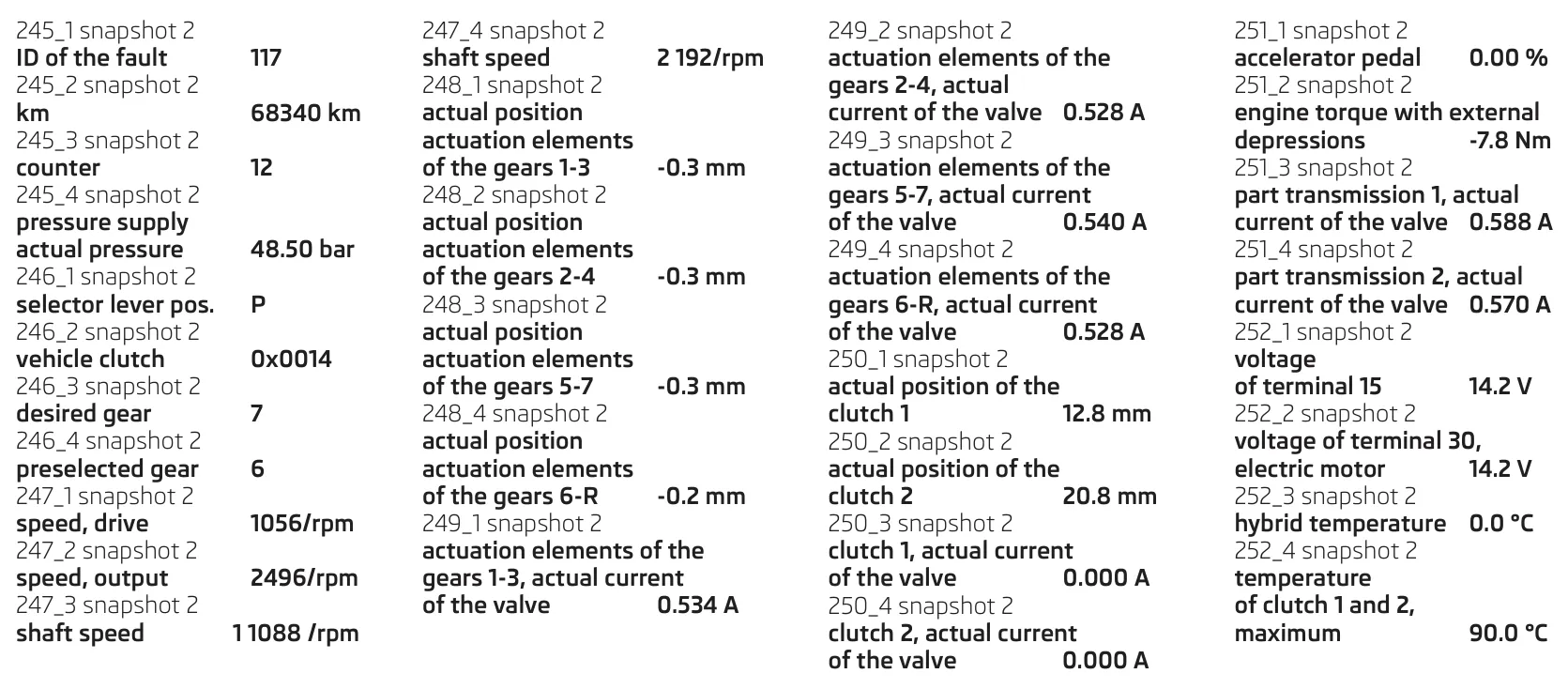
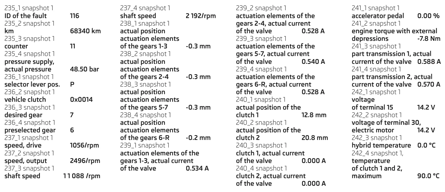
All collision values from the measured value blocks are stored in the event memory. In this way, a printout of the environmental conditions for the last as well as the second last recorded faults is stored. An example of a printout for the environmental conditions from the fault memory is provided below.
Printout of the environmental conditions when the last fault was recorded:
Printout of the environmental conditions when the second last fault was recorded: