
1.6 TDI CR engine (EA189) · Turbocharging/supercharging · Turbocharger
Renewing vacuum unit for turbocharger
Special tools and workshop equipment required
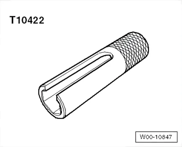
- Socket, 10 mm - T10422-
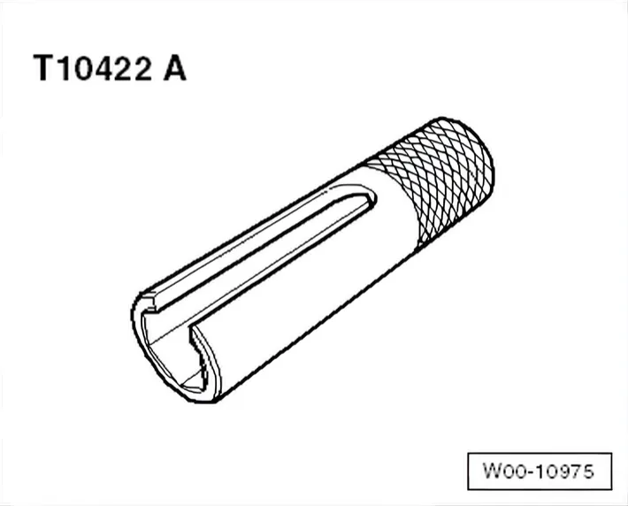
- Socket, 10 mm - T10422 A-
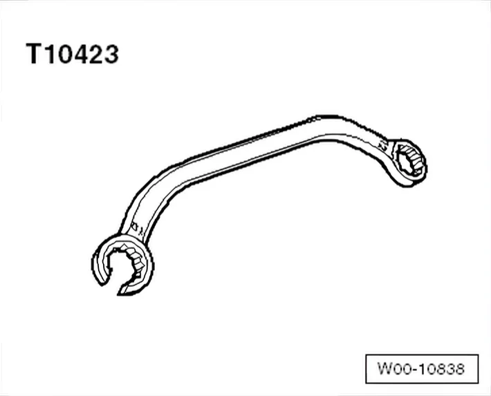
- Ring spanner 10x12 - T10423-
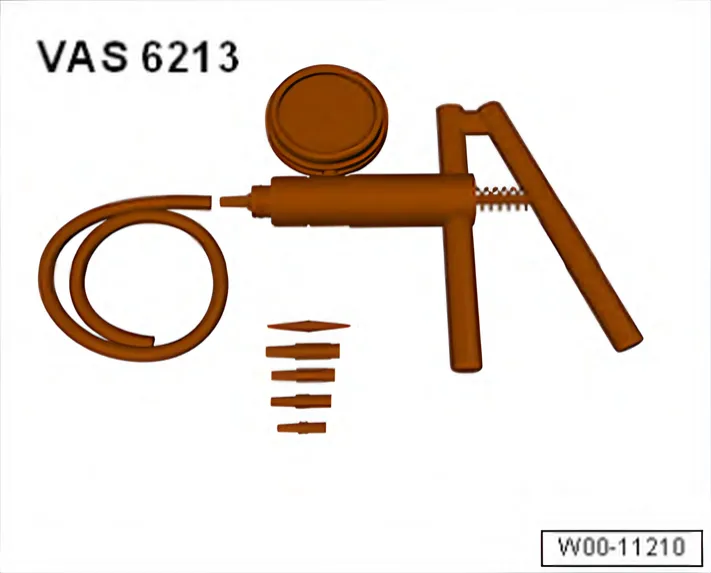
- Hand operated vacuum pump - VAS 6213-
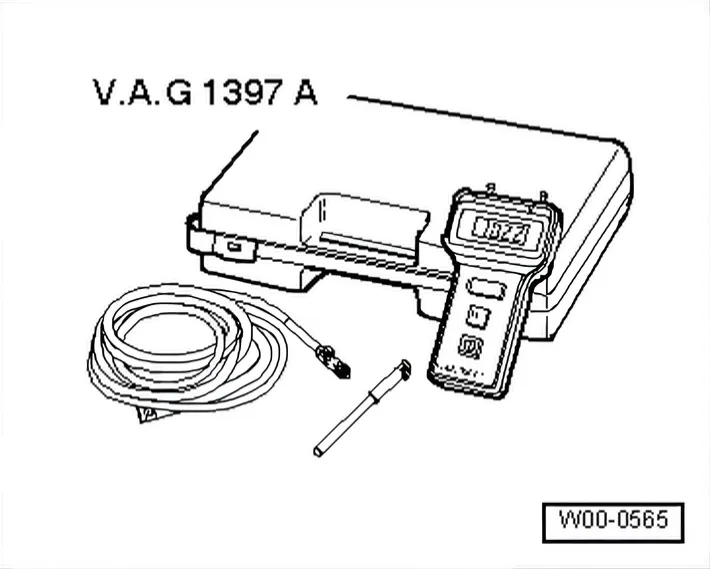
- Turbocharger tester - V.A.G 1397A-
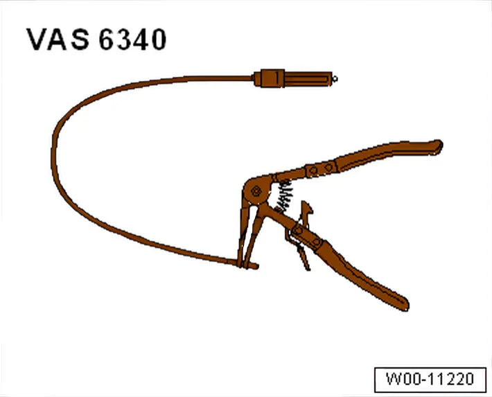
- Hose clamp pliers - VAS 6340-
- Vehicle diagnostic tester
- Red paint, e. g. touch-up pencil “Mars Red” - L 0A3 A01-
Removing
- Remove engine cover panel ⇒ 3.1 Removing and installing engine cover.
- Open heat insulation mat.
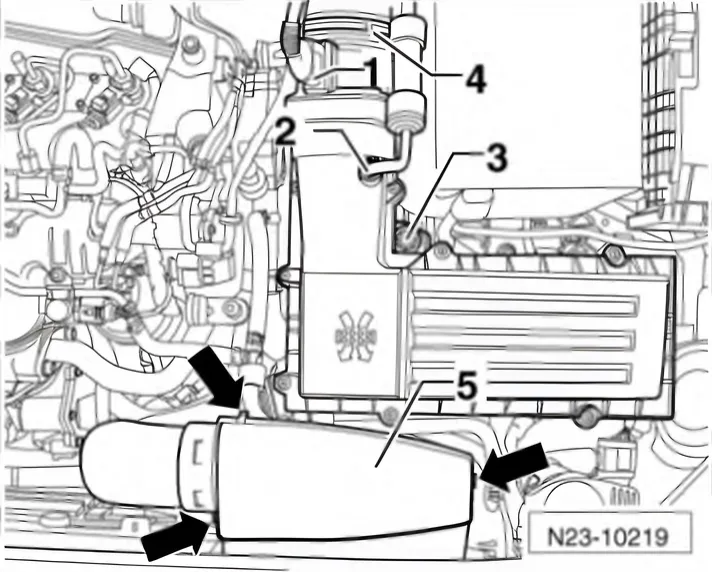
- Open clamp -4-.
- Pull connecting hose to turbocharger off air filter housing.
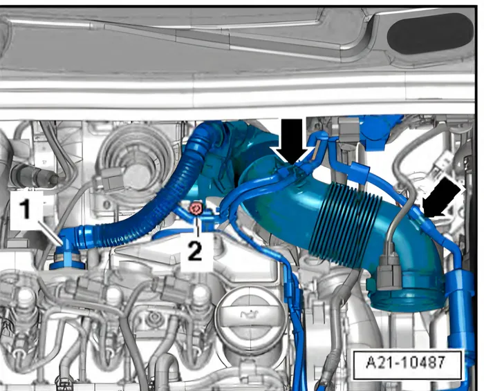
- Remove crankcase breather connecting pipe-1- from cylinder head cover by pressing release buttons.
- Move clear vacuum hoses -arrows-.
- Unscrew bolt -2- (captive bolt).
- Swing air pipe together with intake connection towards rear and pull them off the turbocharger.
- Seal opening in turbocharger with the sealing cap from the spare-parts kit.
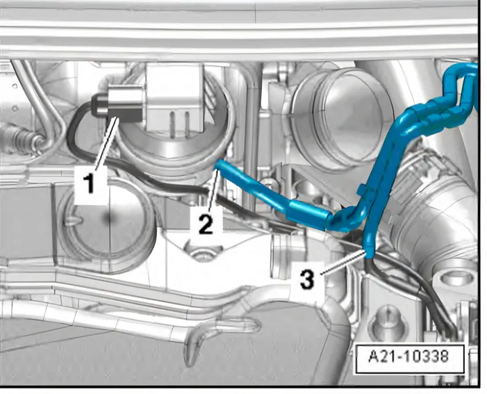
- Pull vacuum hose -2- off turbocharger vacuum unit.
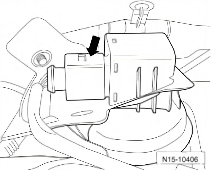
- Release and disconnect connector -1- from position sender for charge pressure positioner - G581-.
- Separate vacuum hose -3-.
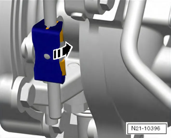
- Remove locking plate.
Vehicles with functioning vacuum adjustment:
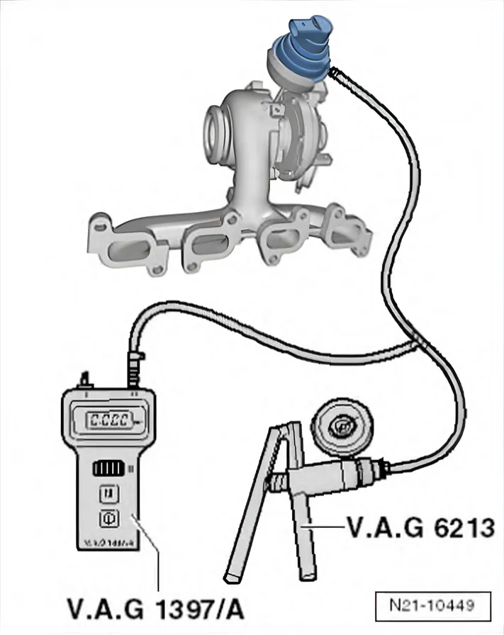
- Connect turbocharger tester - V.A.G 1397A- and hand vacuum pump - VAS 6213- to vacuum unit of turbocharger as shown in illustration.
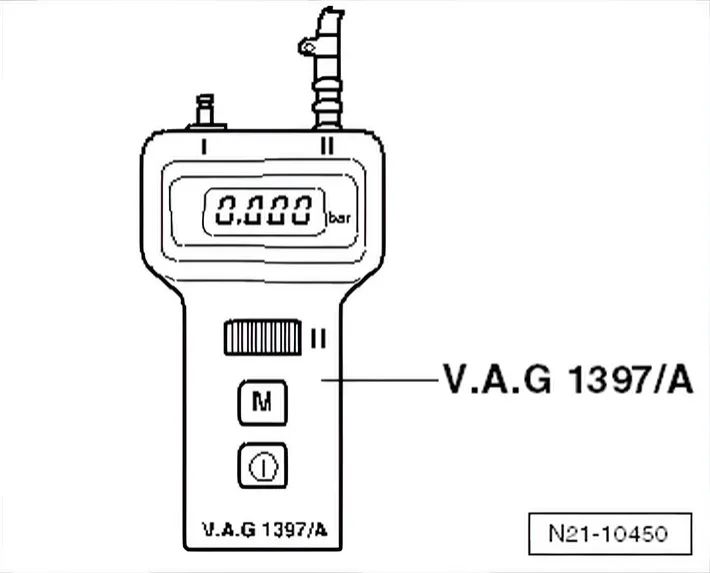
- Set turbocharger tester - V.A.G 1397A- to position »II«.
- Connect vacuum hose to connection »II« of turbocharger tester - V.A.G 1397A-.
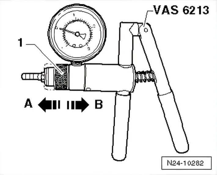
- Move slide ring -1- on hand vacuum pump - VAS 6213- to position -A- for »vacuum«.
Excessive pressure may damage the vacuum unit.
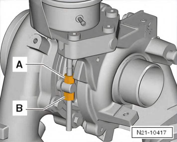
- Place socket AF 10 mm - T10422- or Place socket AF 10 mm
- T10422 A- on securing nut -B-.
- Operate hand vacuum pump - VAS 6213- several times to generate a vacuum of 0.170 bar.
- Read vacuum value displayed on turbocharger tester - V.A.G 1397A-.
- Keep the vacuum constant.
- Fit ring spanner 10x12 - T10423- on lock nut -A-.
- Use ring spanner 10x12 - T10423- to counterhold or loosen lock nut -A-.
- Loosen securing nut -B- from control rod using socket AF 10 mm - T10422- or socket AF 10 mm - T10422 A-.
- Allow partial vacuum to escape from the vacuum unit.
- Unscrew securing nut -B- from control rod using socket AF 10 mm - T10422- or socket AF 10 mm - T10422 A-.
Vehicles with defective vacuum adjustment:
- Place socket AF 10 mm - T10422- or Place socket AF 10 mm
- T10422 A- on securing nut -B-.
- Using suitable tools, push control rod downwards.
- Fit ring spanner 10x12 - T10423- on lock nut -A-.
- Use ring spanner 10x12 - T10423- to counterhold or loosen lock nut -A-.
- Loosen securing nut -B- from control rod using socket AF 10 mm - T10422- or socket AF 10 mm - T10422 A-.
- Unscrew securing nut -B- from control rod using socket AF 10 mm - T10422- or socket AF 10 mm - T10422 A-.
Continued for all vehicles:
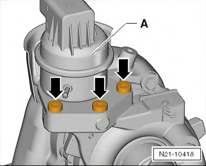
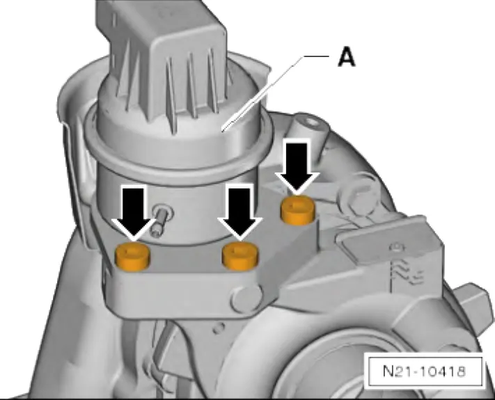
- Unscrew securing bolts -arrows- of vacuum unit.
- Remove vacuum unit with position sender for charge pressure positioner - G581- -A-.
Installing
- If necessary, remove lower securing nut of the control rod from the new vacuum unit.
- Screw locknut by hand onto the control rod as far as possible in the direction of the vacuum unit.
- Guide control rod through adjusting lever on turbocharger.
- Fit vacuum unit with position sender for charge pressure positioner - G581- -A-, and tighten securing bolts.
- Tighten securing bolts -arrows- to 8 Nm.
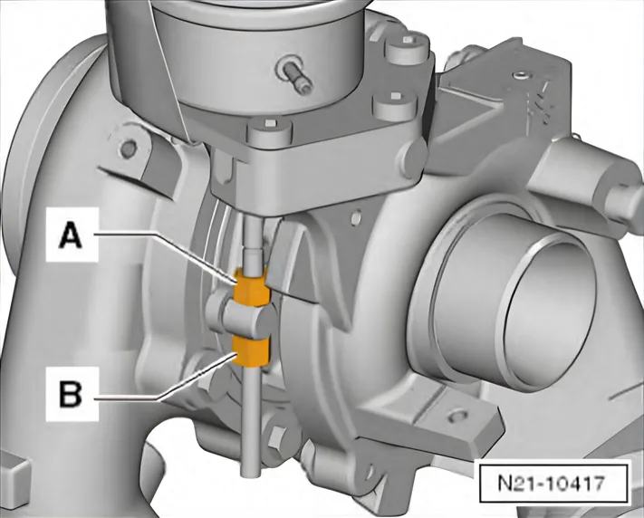
- Slowly unscrew lock nut -A- from control rod by hand. Adjusting lever is resting on the lower »stop«.
- Screw securing nut -B- onto control rod until it lies against adjusting lever.
- Counterhold on securing nut -B- using socket AF 10 mm - T10422- or socket AF 10 mm - T10422 A-.
- Using ring spanner 10x12 - T10423-, slightly tighten lock nut
- A-.
- Connect connector -arrow- to the position sender for the charge pressure positioner - G581- and close the heat protection mat.
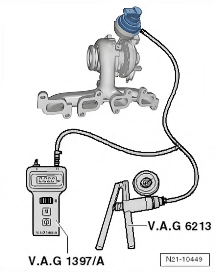
- Connect turbocharger tester - V.A.G 1397A- and hand vacuum pump - VAS 6213- to vacuum unit of turbocharger as shown in illustration.
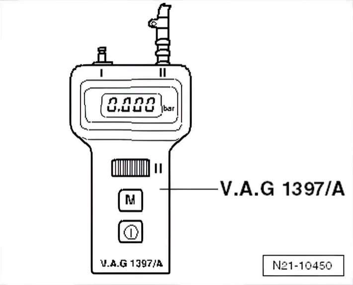
- Set turbocharger tester - V.A.G 1397A- to position »II«.
- Connect vacuum hose to connection »II« of turbocharger tester - V.A.G 1397A-.
- Move slide ring -1- on hand vacuum pump - VAS 6213- to position -A- for »vacuum«.
Excessive pressure may damage the vacuum unit.
During the following procedure for adjusting the control rod, keep the partial vacuum and thus the voltage constant.
Checking adjustment of vacuum unit:
- Connect vehicle diagnostic tester.
- Select Guided Functions.
- Select function Renew vacuum unit of turbocharger.
- Follow instructions on vehicle diagnostic tester.
- Adjust preload by turning nuts -A- and -B-.
Tightening control rod on turbocharger:
- Read vacuum value displayed on turbocharger tester - V.A.G 1397A-, and keep it constant.
- Observe value displayed on vehicle diagnostic tester : it must remain constant.
- Counterhold on lock nut -A- using ring spanner 10x12 - T10423-.
- Fit socket AF 10 mm - T10422- or socket AF 10 mm - T10422 A- on securing nut -B-.
- Tighten securing nut -B- using socket AF 10 mm - T10422- or socket AF 10 mm - T10422 A-.
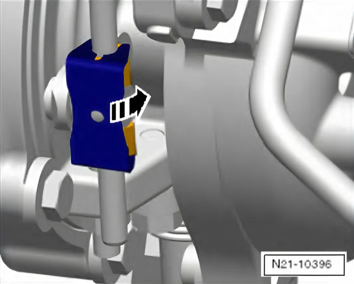
- Push locking plate onto control rod by hand.
- Mark body of vacuum unit with a dot of red colour where it can be clearly seen, using e. g. touch-up pencil “Mars Red” - L 0A3 A01-.
- Remove sealing cap from turbocharger.
- Re-install all engine components.
- ⇒ Rep. gr. 21; Turbocharger; Assembly overview – turbocharger; Assembly overview – turbocharger, Polo
- ⇒ Rep. gr. 23; Vacuum system; Connection diagram – vacuum system; Connection diagram – vacuum system, Polo
- ⇒ Rep. gr. 23; Air filter; Assembly overview – air filter housing; Assembly overview – air filter housing, Polo
- ⇒ Rep. gr. 10; Engine cover panel; Removing and installing engine cover panel
- Continue with the Guided Functions.
Tightening torques on this page
1 torque
In the steps
| Step | Torque |
|---|---|
| Tighten securing bolts -arrows- to 8 Nm. | 8 Nm |