
1.4 MPI engine (EA111) · Fuel supply system · Parts of fuel supply system
Checking fuel pump
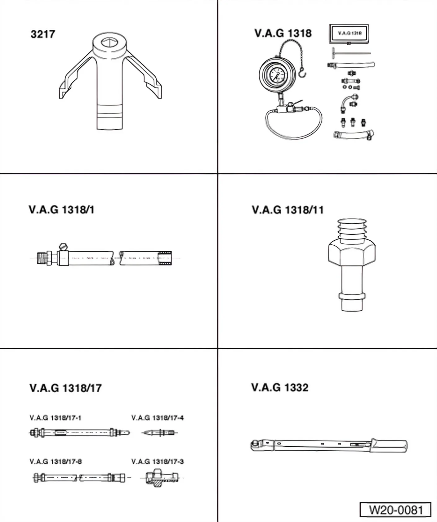
Special tools and workshop equipment required
- Union nut tool - 3217-
- Pressure gauge - V.A.G 1318-
- Adapters - V.A.G 1318/1-
- Adapters - V.A.G 1318/11-
- Adapter set - V.A.G 1318/17-
- Torque wrench (40 to 200
Nm) - V.A.G 1332-
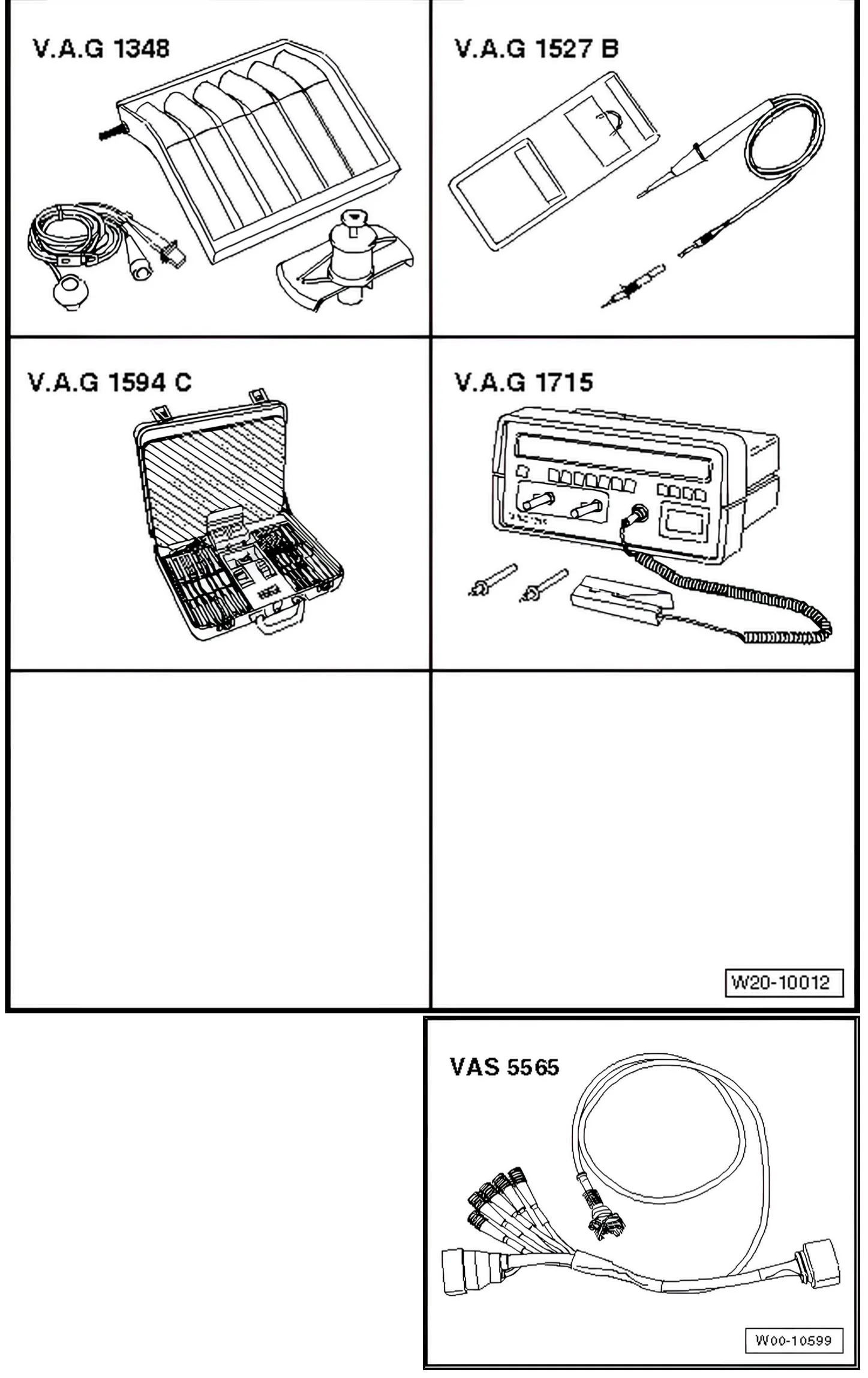
- Injection rate comparison meter - V.A.G 1348-
- Voltage tester - V.A.G 1527 B-
- Adapter set - V.A.G 1594C-
- Multimeter - V.A.G 1715-
- Measuring glass
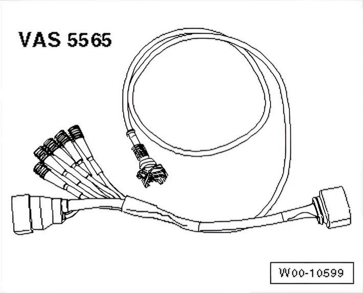
- Test instrument adapter/DSO (5-pin) - VAS 5565-
1.9.1 Checking function and voltage supply
Test conditions
- Fuel pump fuse must be OK. Fuse assignment ⇒ Current flow diagrams, Electrical fault finding and Fitting locations
- Battery voltage must be at least 11.5 V.
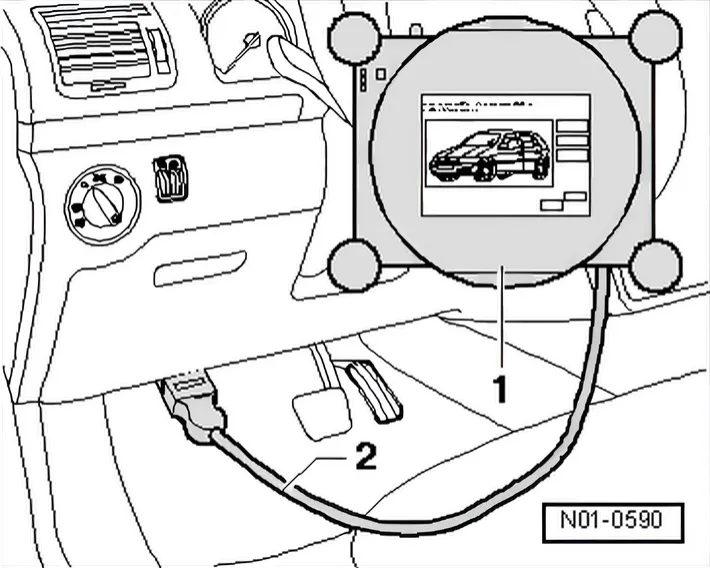
- Connect vehicle diagnostic, testing and information system - VAS 5051 A- as follows:
- Push diagnosis cable connector onto diagnosis connection in driver footwell.
- Switch ignition on.
- Press buttons on display one after the other for “Vehicle selfdiagnosis”, “01 - Engine electronics” and “Final control diagnosis”.
- Press right arrow button on display up to final control diagnosis for fuel pump electronics.
The fuel pump must now run slowly up to maximum speed.
Switch off ignition.
If fuel pump does not run:
- Fold rear bench seat forwards.
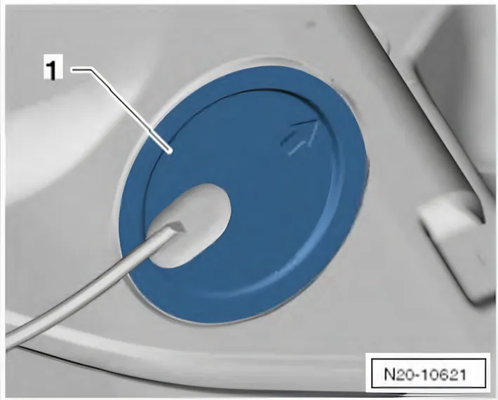
- Remove cover -1- from fuel delivery unit.
- First check that the connector is fitted securely by pulling the connector without pressing the catch.
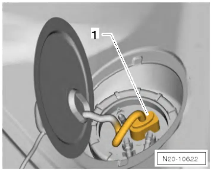
- Pull connector off fuel delivery unit flange.
- Check the contacts on the connector and on the fuel delivery unit for damage.
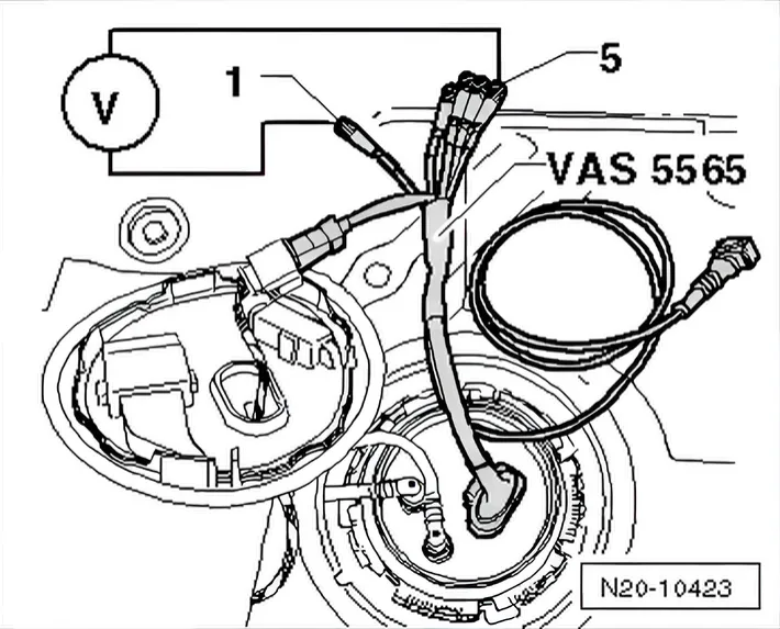
- Connect test instrument adapter/DSO (5-pin) - VAS 5565- to connector and fuel delivery unit.
- Connect voltage tester - V.A.G 1527B- to wires -1- and -5- of adapter.
Switch ignition on.
- LED must light up briefly.
If LED does not light up:
- Locate and eliminate open circuit referring to current flow diagram: ⇒ Current flow diagrams, Electrical fault finding and Fitting locations.
If LED lights up: the voltage supply is OK.
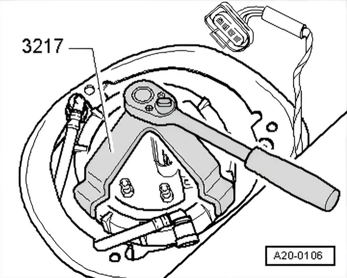
- Unscrew union nut with union nut tool - 3217-.
- Check that electrical wires between flange and fuel pump are connected.
If no open circuit can be found:
- Renew fuel delivery unit.
1.9.2 Checking fuel pressure
Test sequence
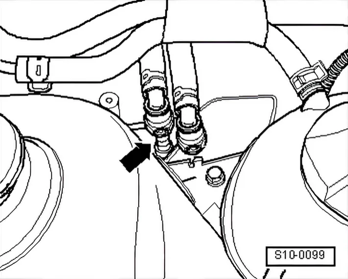
- Separate connection for fuel supply line -arrow- and catch escaping fuel with a cloth.
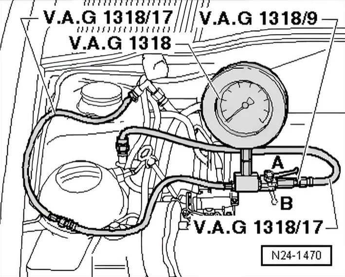
- Connect pressure tester - V.A.G 1318- using adapters - V.A.G 1318/9- and -1318/17- as shown.
- Open the pressure tester shut-off tap. The handle points in direction of flow.
- Start engine and run at idling speed.
- Measure fuel pressure.
Specification: 3.90 ... 4.20 bar
If specification is not obtained
- Switch off ignition.
- Checking holding pressure ⇒ 1.9.3 Checking holding pressure.
1.9.3 Checking holding pressure
Prerequisites for check
- Fuel pressure OK and pressure tester - V.A.G 1318- connected.
Test sequence
- Remove fuse holder cover.
- Remove fuse for fuel pump from fuse holder. Fuse assignment ⇒ Current flow diagrams, Electrical fault finding and Fitting locations
- Connect remote control for V.A.G 1348 - V.A.G 1348/3A- with adapter cable - V.A.G 1348/3-2- to fuse socket and battery positive (+).
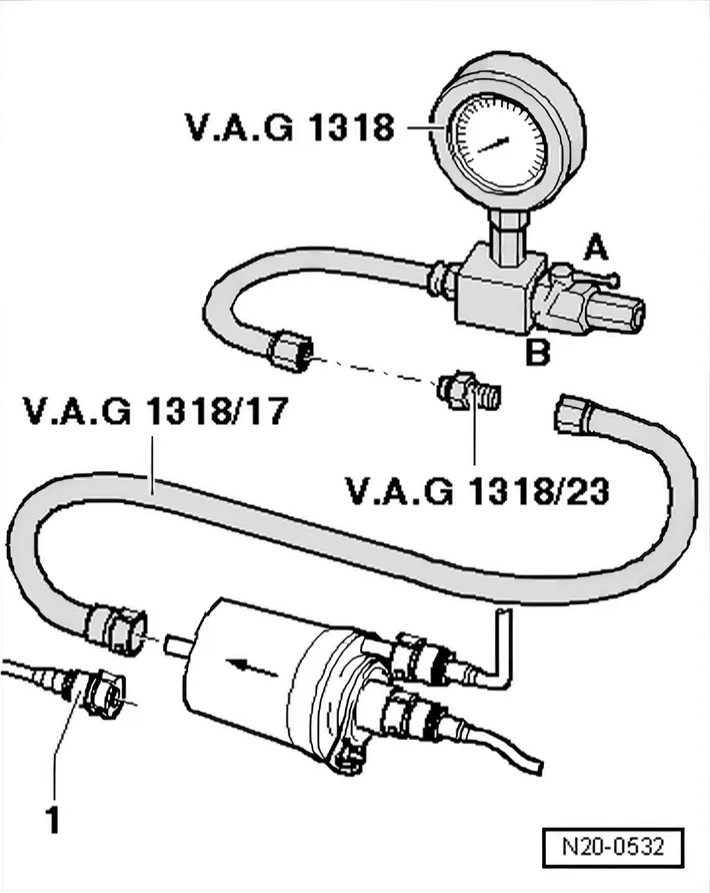
- Pull supply line -1- off output side of fuel filter.
- Connect pressure tester - V.A.G 1318- using connector - V.A.G 1318/23- and adapter set - V.A.G 1318/17- as shown.
- Close pressure gauge shut-off tap (lever at right angles to through-flow direction, position -B-).
- Operate remote control for V.A.G 1348 - V.A.G 1348/3A- for approximately 10 seconds to fill fuel filter and build up pressure in the system.
- Watch pressure drop on pressure gauge. Pressure must remain above 3 bar for 10 minutes.
If the pressure drops further:
- Check line connections for leaks.
If no fault in lines is detected:
- Renew fuel pressure regulator.
1.9.4 Checking fuel delivery rate
Test conditions
- Voltage supply OK.
- Remote control for V.A.G 1348 - V.A.G 1348/3A- is connected.
Test sequence
- Remove filler cap from fuel tank filler neck.
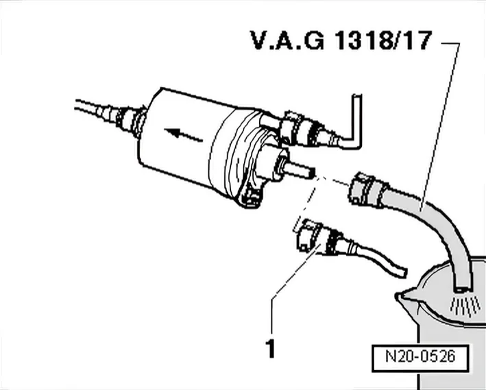
- Pull off return line -1- from fuel pressure regulator.
- Connect adapter set - V.A.G 1318/17- to fuel pressure regulator and hold end of adapter in measuring glass.
- Operate remote control -V.A.G 1348/3A- for approx. 5 seconds to fill fuel filter.
- Empty measuring glass.
- The delivery rate of the fuel pump depends on the voltage. Connect multimeter to both outer contacts (connector remains connected) of fuel pump using adapter cables from auxiliary measuring set - V.A.G 1594C-.
- Operate remote control for 30 seconds while measuring battery voltage.
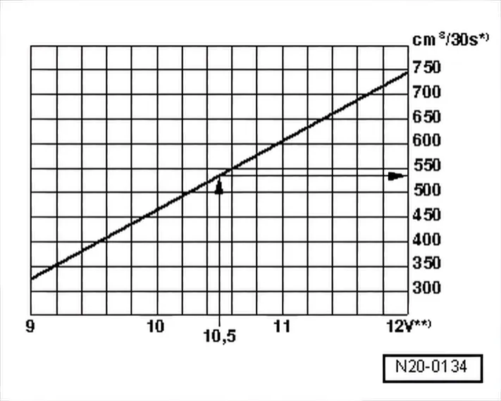
- Compare quantity of fuel delivered with specification.
8) Minimum delivery cm3/30 seconds
9) Voltage at fuel pump with engine not running and pump running (approx. 2 volts less than battery voltage).
Reading example:
During the test, a voltage of 10.5 volts is measured. At this pump voltage, the minimum delivery rate is 540 cm3/30 s.
If minimum delivery rate is not attained:
- Check supply line to filter for possible restrictions (kinks) or blockages.
If fuel line is OK
- Check fuel delivery rate before fuel filter.
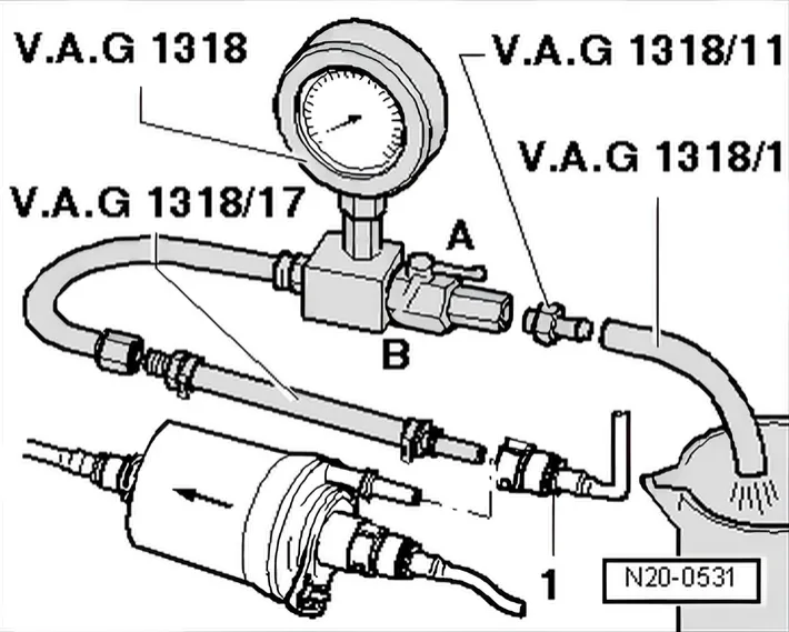
- Pull off supply line -1- from fuel filter inlet.
- Connect pressure tester - V.A.G 1318- using adapters - V.A.G 1318/17- as shown.
- Push adapter - V.A.G 1318/1- onto adapter - V.A.G 1318/11- of pressure tester and hold it in measuring glass.
- Open shut-off tap of pressure tester. The lever then points in direction of flow -A-.
- Operate remote control for V.A.G 1348 - V.A.G 1348/3A-. Then slowly close shut-off tap until a pressure of 3 bar is displayed on pressure gauge. From this point on do not move position of shut-off tap.
- Empty measuring glass.
- Operate remote control again for 30 seconds. Compare delivery rate with the value determined in the first measurement.
If the minimum delivery rate is now attained:
- Renew fuel filter.
If the minimum delivery rate is again not attained
- Remove fuel delivery unit and check filter strainer for soiling.
Only if still no fault has been detected:
- Renew fuel delivery unit.
1.9.5 Checking current consumption
- Check current draw of fuel pump as follows:
- Reconnect all disconnected fuel lines.
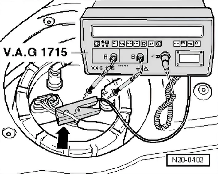
- Connect multimeter - V.A.G 1715- to wire -arrow- to contact 1 of connector using pick-up clamp.
- Start engine and run at idling speed.
- Measure current draw of fuel pump. Specification: max. 8 amps.
The starting current for the fuel pump can be briefly above specifications when starting the engine.
If the current draw is exceeded:
- Fuel pump defective, renew fuel pump unit.