
1.4 MPI engine (EA111) · Fuel supply system · Parts of fuel supply system
Bleeding fuel system
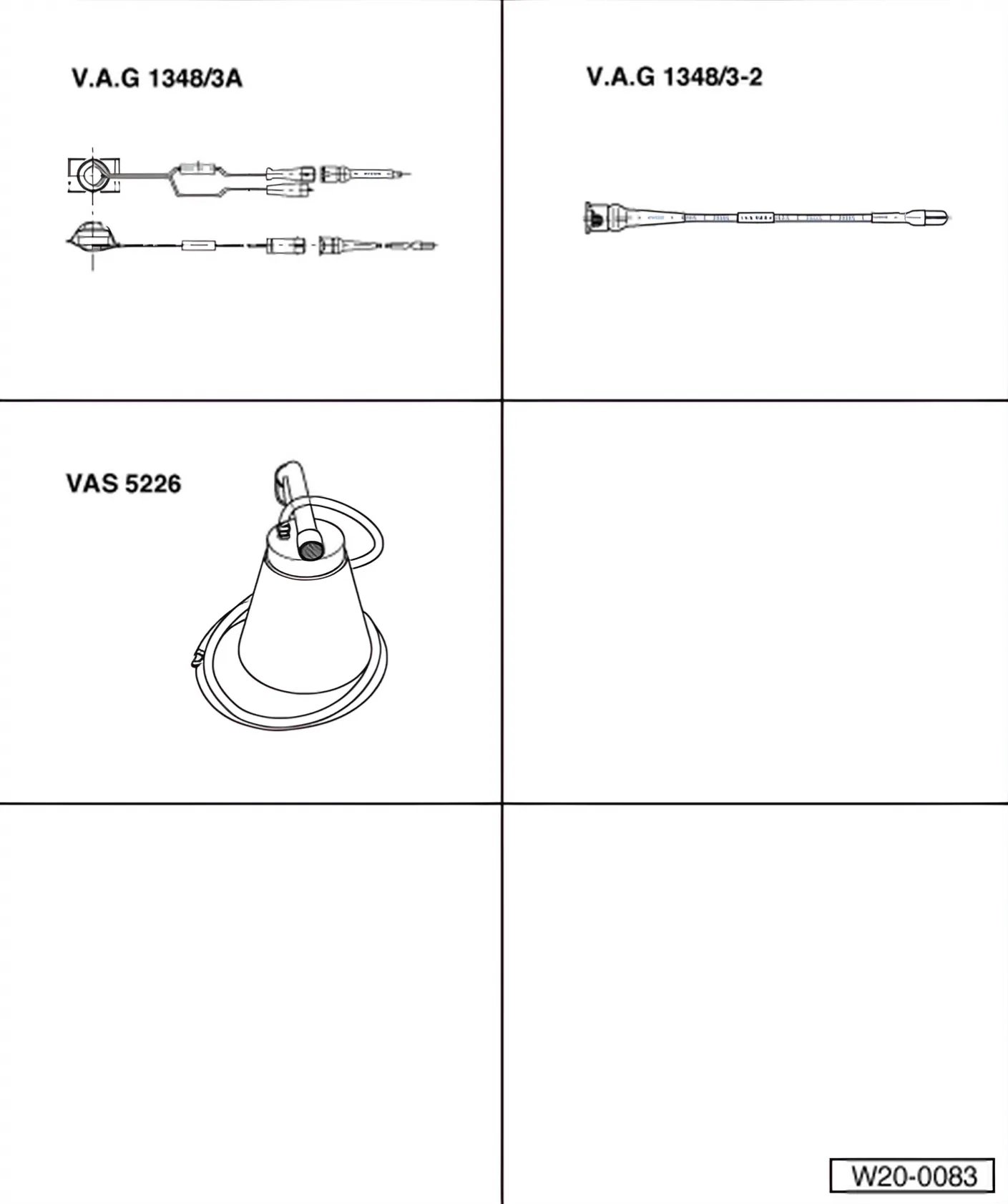
Special tools and workshop equipment required
- Remote control for V.A.G 1348 - V.A.G 1348/3A-
- Adapter line - V.A.G 1348/3-2-
- Diesel extractor - VAS 5226-
- Adapters - V.A.G 1318/20-
- Adapters - V.A.G 1318/20-1-
Conditions
- Fuses must be OK.
- Battery voltage must be at least 11.5 V.
- Fuel pump relay must be OK.
Sequence of operations
- Remove fuse holder cover.
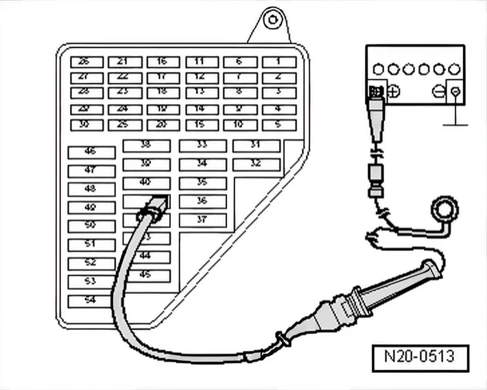
- Pull the fuse for the fuel pump out of the fuse holder. Fuse assignment ⇒ Current flow diagrams, Electrical fault finding and Fitting locations
- Connect remote control for V.A.G 1348 - V.A.G 1348/3A- with adapter cable - V.A.G 1348/3-2- to right contact of fuel pump and battery positive (+).
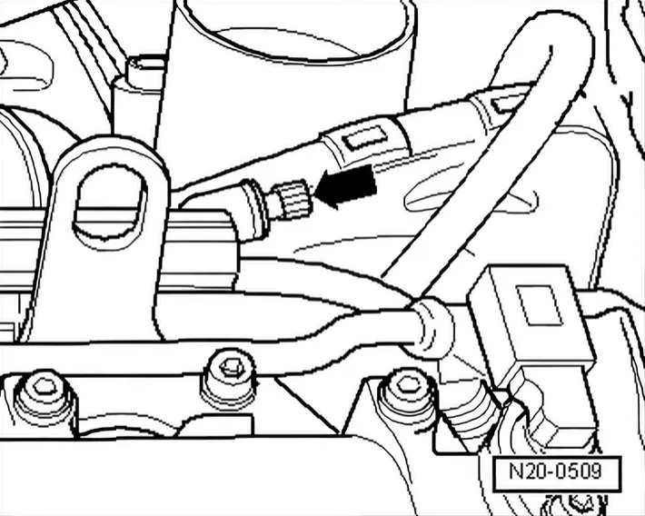
- Remove cover -arrow- from breather valve.
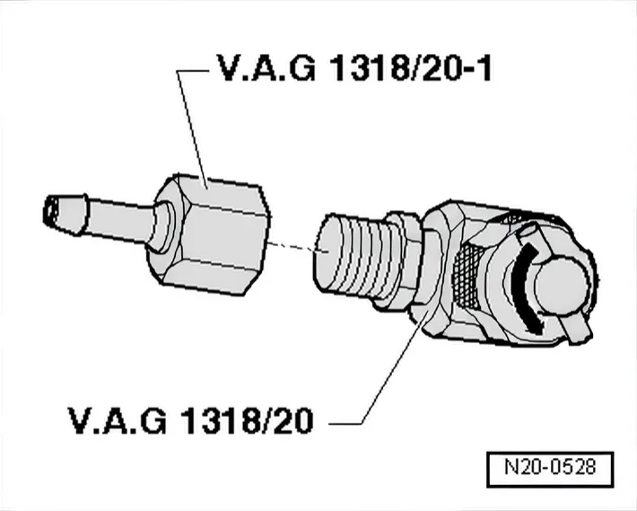
- Screw adapter -V.A.G 1318/20-1- onto adapter - V.A.G 1318/20-.
- Turn valve (on T-piece) anti-clockwise until it is entirely open.
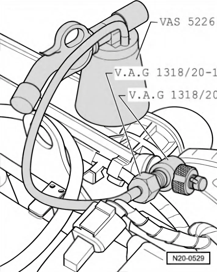
- Screw adapter -V.A.G 1318/20- onto the bleed valve (handtight).
- Connect hose from diesel extractor -VAS 5226- as illustrated.
- Turn valve on T-piece clockwise into bleed valve to stop.
- Check adapter and hose connections for leaks.
- Operate remote control for V.A.G 1348 - V.A.G 1348/3A- until fuel flows free of air bubbles from breather valve.
- Turn valve (on T-piece) anti-clockwise until it is entirely open again.
- Clamp off hose from diesel extractor -VAS 5226- (e.g. using hose clamps up to Ø 25 mm - 3094- ) and pull it off adapter - V.A.G 1318/20-1-.
- Unscrew adapter -V.A.G 1318/20- from bleeder valve.