
1.4 MPI engine (EA111) · Cylinder head, valve gear · Cylinder head
Removing and installing cylinder head
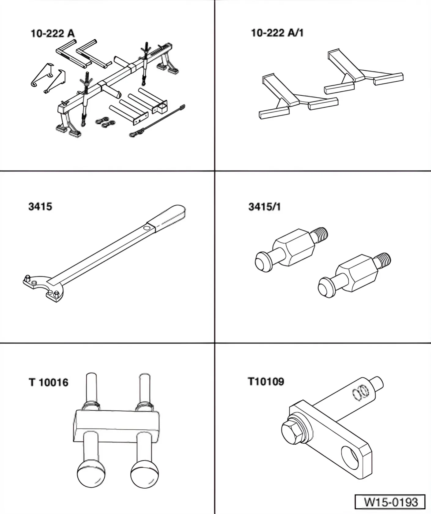
Special tools and workshop equipment required
- Support - 10 - 222 A-
- Rack - 10 - 222 A /1-
- Counter-hold tool - 3415-
- Pin - 3415/1-
- Camshaft lock - T10016-
- Bracket - T10109-
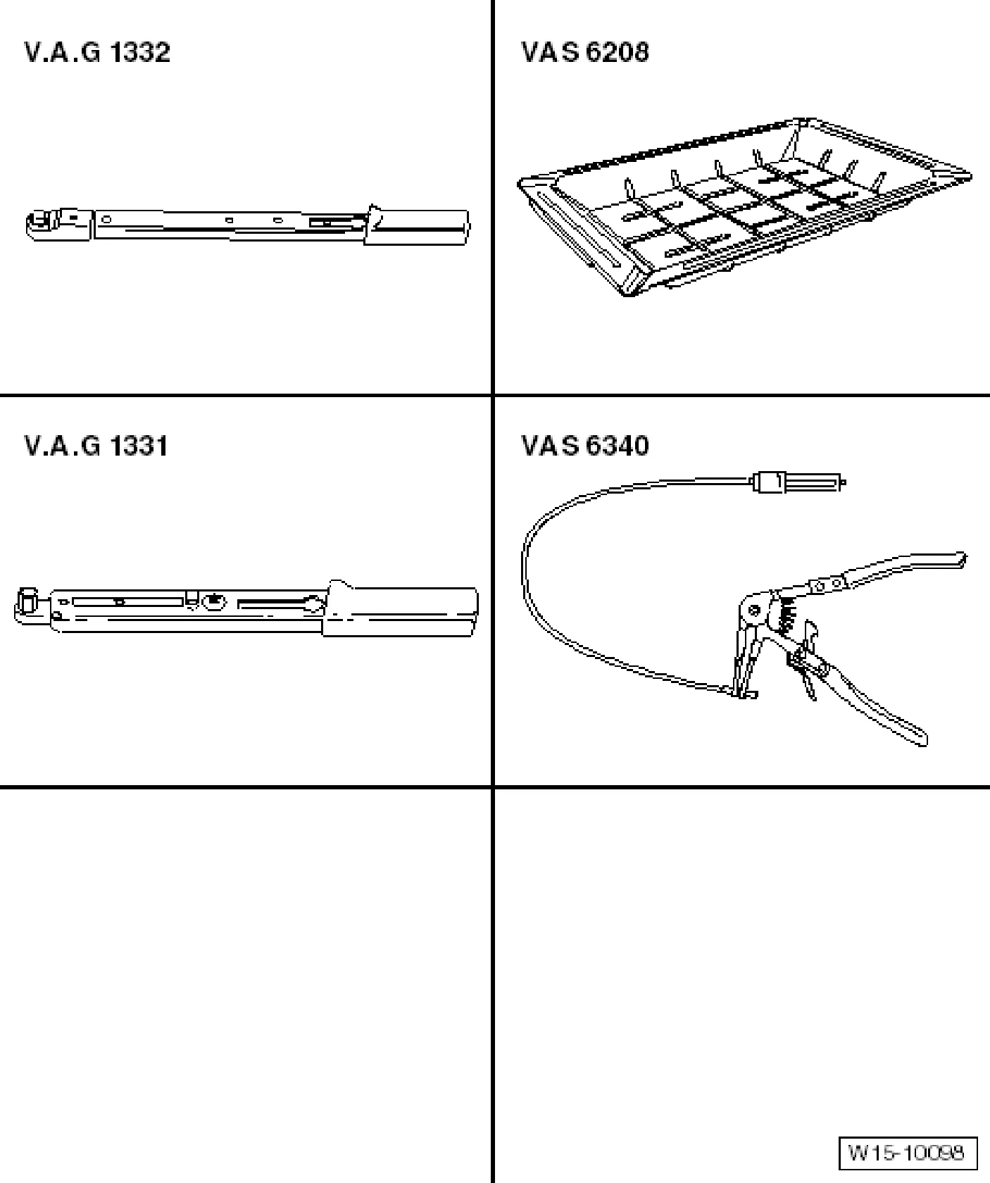
- Torque wrench (40 to 200 Nm) - V.A.G 1332-
- Drip tray for workshop hoist - VAS 6208-
- Torque wrench (5 … 50 Nm) - V.A.G 1331-
- Hose clamp pliers - VAS 6340-
- Sealant - D 154 103 A1-
1.6.1 Removing
Conditions
- The engine must be no more than warm to touch.
- The pistons cannot be positioned at TDC.
- First check whether a coded radio is fitted. If so, obtain antitheft code.
- With the ignition switched off, disconnect battery earth strap.
- Remove camshaft housing cover, if fitted.
- First remove main drive toothed belt ⇒ 1.3 Removing, installing and tensioning toothed belt.
- Remove camshaft housing ⇒ 1.5 Removing and installing camshaft housing.
- Remove roller rocker fingers together with support elements and lay aside on a clean surface.
- Ensure that roller rocker fingers and support elements are not interchanged.
- Open and close expansion tank cap to release pressure in cooling system.
- Drain coolant ⇒ 1.6 Draining and adding coolant.
- Loosen hose clips and pull coolant hoses off coolant thermostat housing.
- Remove oil dipstick guide tube.
- Pull fuel supply line off fuel rail.
- Seal lines so that fuel system is not contaminated by dirt.
- Observe rules for cleanliness ⇒ 1.3 Rules for cleanliness.
- Detach or disconnect the following components:
- Hose from activated charcoal filter to intake manifold
- Vacuum hose from brake servo to intake manifold
- 2-pin connector from knock sensor (back of cylinder block) as well as 4-pin connector from intake manifold pressure sender with intake air temperature sender
- Connector from engine speed sensor, located below oil dipstick guide tube bracket
- Connector from coolant temperature sender, oil pressure switch and -N18- exhaust gas recirculation valve
- Connector of throttle valve control module
- Connectors for injectors
- Connector from heated vacuum valve on oil separator
- Hose from crankcase breather
- Pull off or disconnect all other electrical connections as necessary from engine and lay to side.
- Remove fuel rail complete with all injectors ⇒ 1.10 Checking injectors.
- Remove thermostat housing from cylinder head.
- Detach front exhaust pipe from exhaust manifold.
- Remove securing bolt for toothed belt rear guard (near righthand lifting eye).
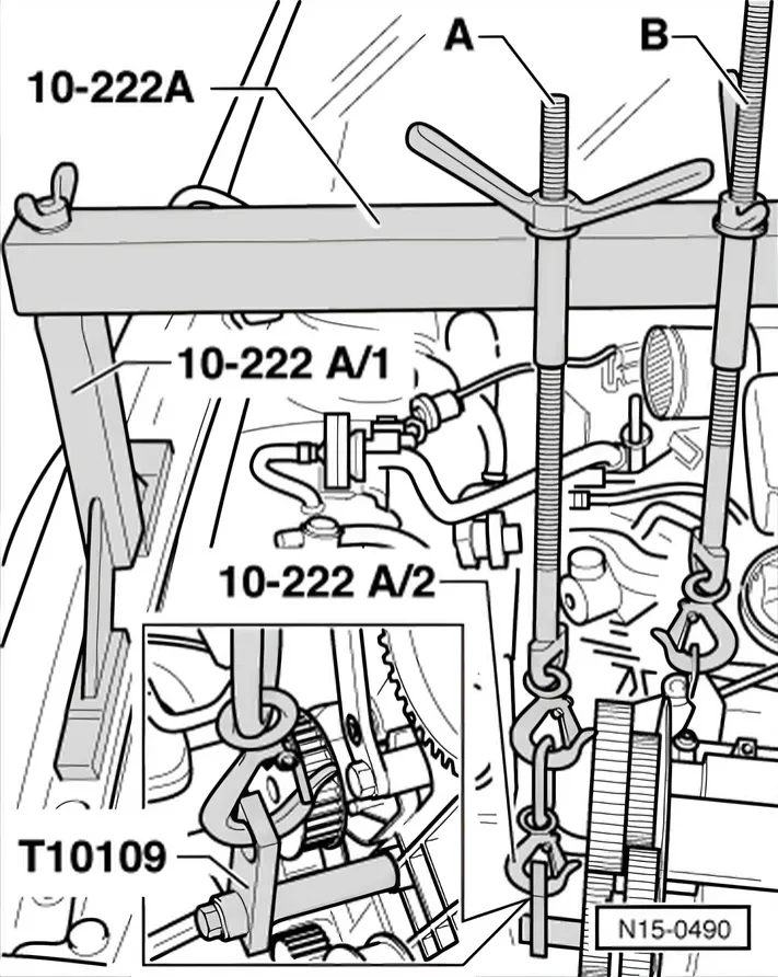
- Now the engine must be lifted again slightly with spindle -B-.
- Screw bracket -T10109-, as illustrated, into cylinder block threaded hole in vicinity of coolant pump. Torque setting: 20 Nm
- Lift engine slightly using second spindle -A- until spindle -B- is relieved.
- Remove spindle -B-.
- Pull clamp securing coolant pipe to coolant pump off thermostat housing.
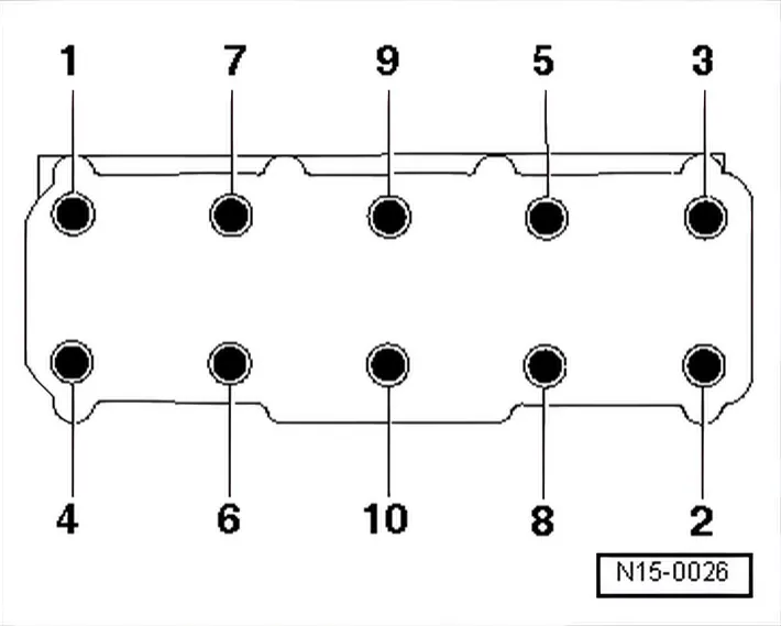
- Loosen cylinder head bolts in sequence given and then remove completely.
- Carefully remove cylinder head.
1.6.2 Installing
- Place clean cloths in cylinders so that no dirt or emery cloth particles can get in between cylinder wall and piston.
- Now carefully clean sealing surfaces of cylinder head and cylinder block. When doing this, ensure that surfaces are not scored or scratched (if sand paper is used, grade must not be less than 100).
- Carefully remove metal particles, emery residue and cloths.
- Set no. 1 cylinder piston to top dead centre and then turn crankshaft back slightly.
- Fit new cylinder head gasket. Inscription (Part No.) must be readable.
- Fit cylinder head. When doing this, observe centring pins in cylinder block.
- Insert new cylinder head bolts and tighten hand-tight.
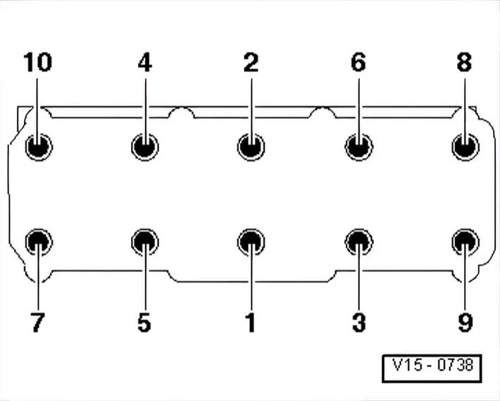
- Tighten cylinder head in sequence as follows:
- Tighten all bolts to 30 Nm.
- Then tighten all bolts 1/4 turn (90°) further using a rigid wrench.
- Then tighten all bolts again 1/4 turn (90°) further.
- Install supporting elements in cylinder head and fit respective roller rocker finger onto respective valve stem end or supporting element.
- Install camshaft housing ⇒ 1.5 Removing and installing camshaft housing.
Specified torque for securing bolts of camshaft housing cover: 10 Nm
Further assembly is basically a reverse of the dismantling sequence.
Filling with new coolant ⇒ 1.6 Draining and adding coolant.