
1.4 MPI engine (EA111) · Fuel supply system · Activated charcoal filter system
Activated charcoal filter system
Assembly overview - parts of activated charcoal filter system ⇒ 3.1 Assembly overview - parts of activated charcoal filter system
Checking fuel tank breather ⇒ 3.2 Checking fuel tank breather
Observe safety precautions ⇒ 1.2 Safety regulations for working on fuel supply.
Observe rules for cleanliness ⇒ 1.3 Rules for cleanliness.
3.1 Assembly overview - parts of activated charcoal filter system
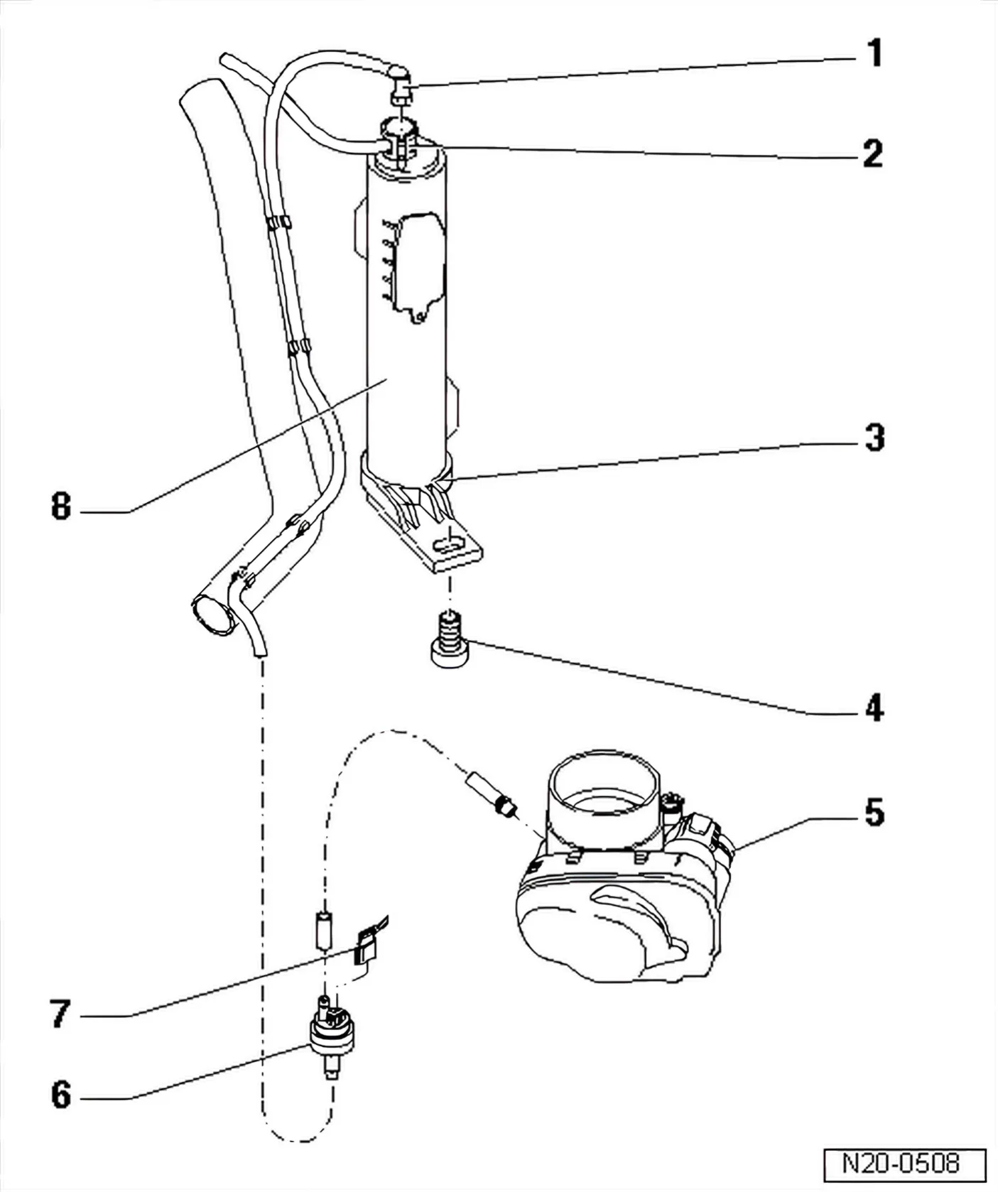
- 1 Breather hose
- Ensure firm seating.
- 2 Pressure retention valve with connecting hose
- Ensure firm seating.
- From gravity valve on fuel tank
- 3 Breather connection
- Visible from below
- 4 10 Nm
- 5 Throttle valve module - J338-
- With intake connection.
- 6 Activated charcoal filter solenoid valve 1 - N80-
- Valve closed with ignition switched off
- When engine is warm, valve will be activated (pulsed) by engine control unit
- 7 Connector
- 8 Activated charcoal filter
- Location: in rear right wheel housing.
3.2 Checking fuel tank breather
Special tools and workshop equipment required
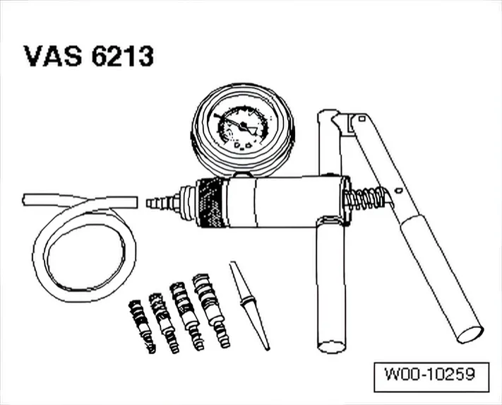
- Hand vacuum pump VAS 6213
Prerequisites for check
- Ignition must be switched off.
Test sequence
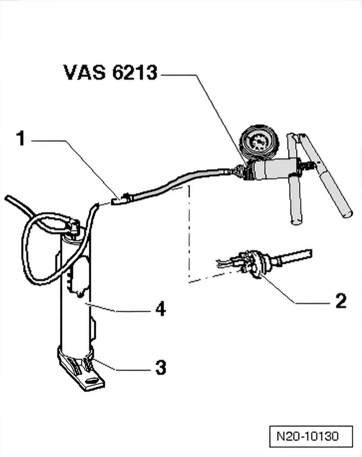
- First pull breather hose -1- from activated charcoal filter on activated charcoal filter system solenoid valve 1 - N80- -2-.
- Connect hand vacuum pump VAS 6213 to hose -1- as shown.
- Operate hand vacuum pump V.A.G 6213 several times. There must be no development of vacuum.
If vacuum builds up:
- Check breather opening -3- on lower activated charcoal filter -4- for soiling, clean if necessary.
If vacuum does not build up:
- Temporarily seal breather opening -3- and operate vacuum pump again several times. Vacuum must build up.
If vacuum does not build up:
- Renew activated charcoal filter.