
1.4 MPI engine (EA111) · Cylinder head, valve gear · Cylinder head
Removing, installing and tensioning toothed belt
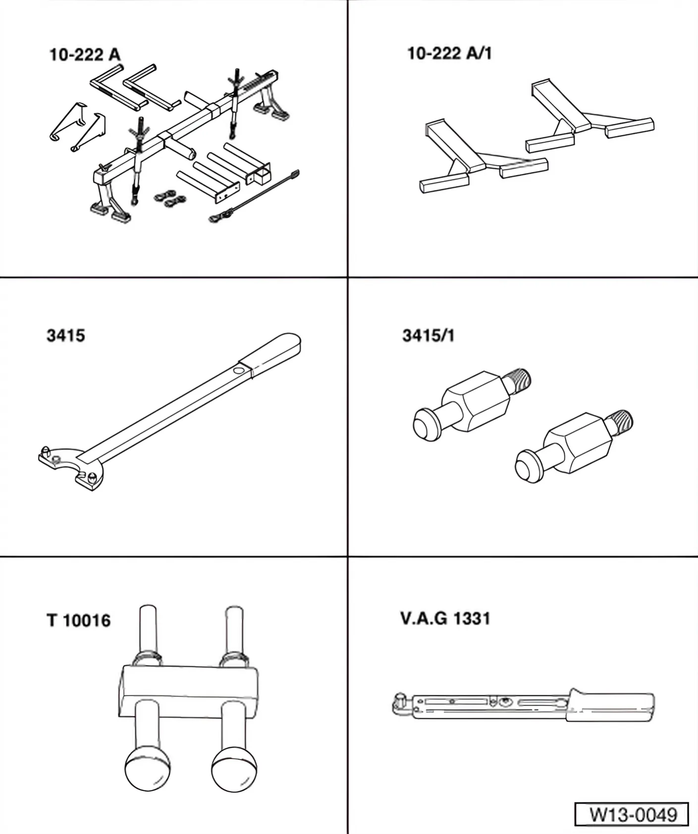
Special tools and workshop equipment required
- Support - 10 - 222 A-
- Rack - 10 - 222 A /1-
- Counter-hold tool - 3415-
- Pin - 3415/1-
- Camshaft lock - T10016-
- Torque wrench (5 … 50 Nm) - V.A.G 1331-
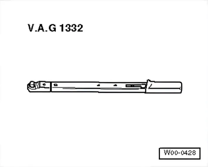
- Torque wrench (40 to 200 Nm) - V.A.G 1332-
1.3.1 Removing
- Remove upper toothed belt guard.
- Remove engine splash protection.
- Remove front right wheel housing liner: ⇒ General body repairs, exterior; Rep. gr. 66; Removing and installing wheel housing liner.
- Mark the direction of rotation of the poly V-belt and remove belt ⇒ 1.4 Removing and installing poly-V belt.
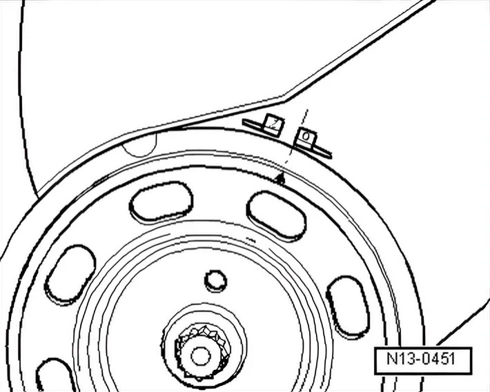
- Position crankshaft at TDC No. 1 cylinder. The notch on pulley must align with edge of -O- mark.
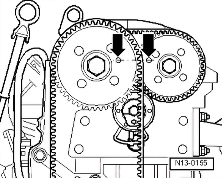
- The locking pin holes in the camshaft pulleys must align with the fitting holes in the camshaft housing -arrows-.
Fix both camshaft pulleys with camshaft lock -T10016- as follows:
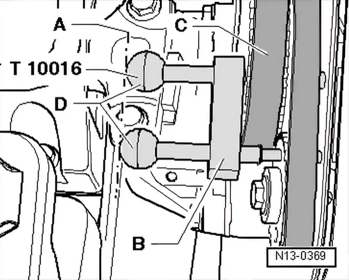
- Guide both locking pins through camshaft pulley locking pin holes to stop in camshaft housing fitting holes.
- Slide retainer -B- to stop against inlet camshaft pulley -C-.
The engine must be lowered slightly as follows to enable the crankshaft pulley to be removed:
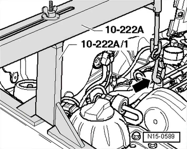
- Fit support bracket - 10 - 222 A- with frame - 10 - 222 A /1- as shown.
- Unscrew coolant expansion tank and lay to side.
- Remove upper securing bolt from lower toothed belt guard beneath engine bracket.
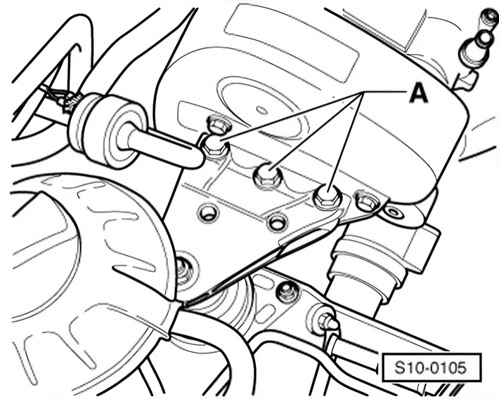
- Take up weight of engine and remove securing bolts -A-.
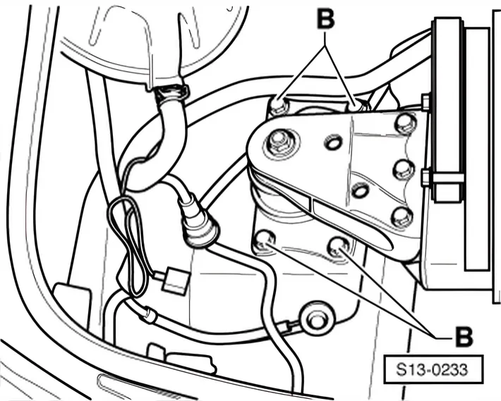
- Remove securing bolts -B- and remove assembly mounting.
- Remove engine bracket on cylinder head.
- Lower engine until the pulley securing bolt is accessible.
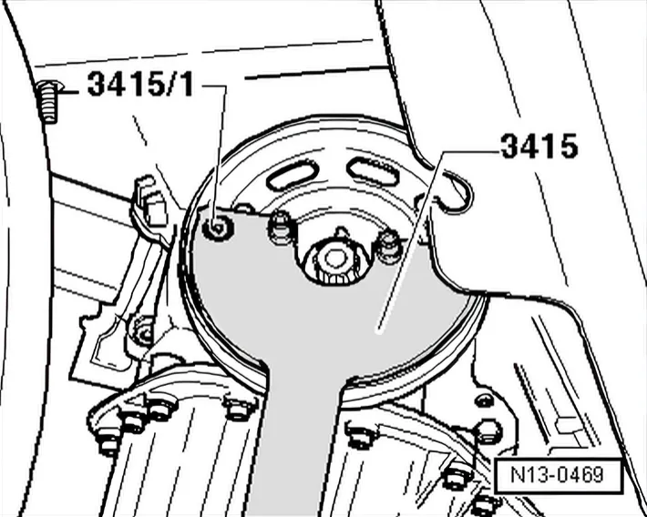
- Remove pulley securing bolt and toothed belt pulley. Hold belt pulley with counterhold - 3415- and pin 3415/1.
- Remove pulley. Refit securing bolt with two washers and tighten to secure toothed belt pulley.
- Remove poly V-belt tensioning element on vehicles with an air conditioning system.
- Remove lower toothed belt guard.
- Mark direction of rotation of both toothed belts.
Remove main drive toothed belt:
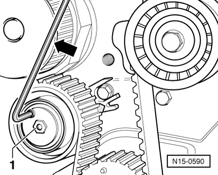
- Release main drive tensioning roller -1- and slacken toothed belt by turning tensioning roller anti-clockwise -arrow-.
- Loosen clamping bolt on tensioning roller.
- Remove toothed belt.
Removing coupling drive toothed belt:
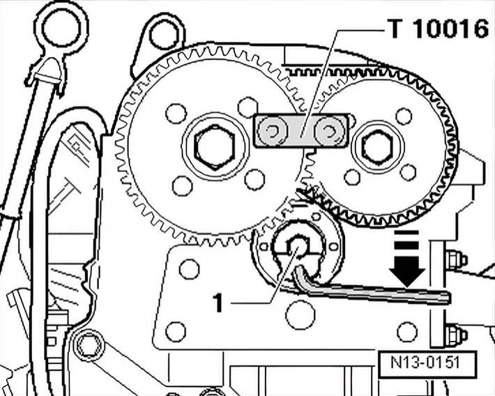
- Release tensioning roller from coupling drive -1- and release toothed belt by turning tensioning roller clockwise.
- Remove coupling drive tensioning roller.
- Remove toothed belt.
1.3.2 Installing
Conditions
- The pistons cannot be positioned at TDC.
- The crankshaft toothed belt pulley is secured to the crankshaft with the securing bolt and two washers.
- Camshaft pulleys locked into camshaft housing fitting holes with camshaft lock - T10016- and secured against turning.
Sequence of operations
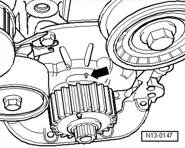
- Set crankshaft to TDC No. 1 cylinder. The tooth with end ground down must align with the mark on the oil pump -arrow-.
- Fit toothed belt for coupling the camshafts in a clockwise direction starting at top on inlet camshaft pulley and then onto exhaust camshaft pulley. The slack section of the toothed belt must be at the bottom. Note direction of rotation with used belts.
Install coupling drive tensioning roller as follows
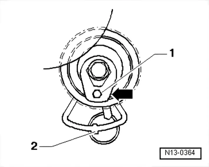
- Turn coupling drive tensioning roller clockwise towards marking window -arrow- using a hexagon key -1- (tensioning roller in relaxed position).
- Press lower part of toothed belt for coupling the camshafts upwards with tensioning roller and fit tensioning roller securing bolt.
- Tighten securing bolt hand tight. The lug in the base plate must engage in the hole in the cylinder head -2-.
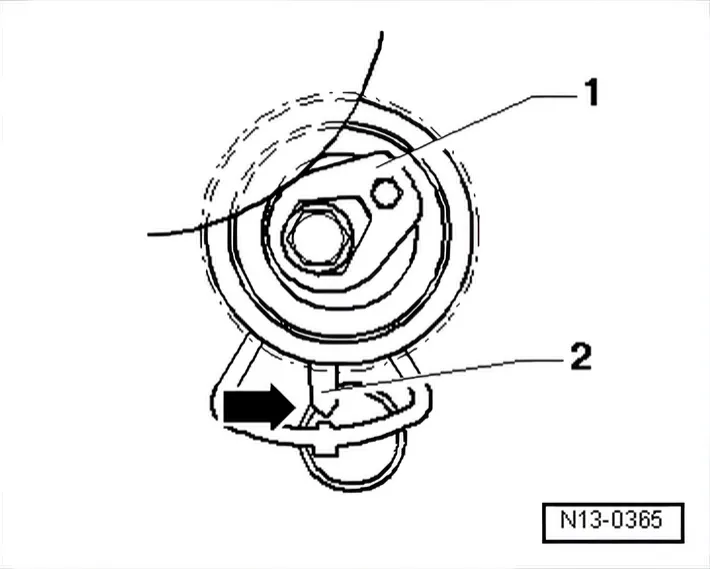
- Then tension toothed belt by turning tensioning roller anticlockwise using a hexagon key -1-, until indicator -2- aligns over lug in base plate in marking window -arrow-.
- Tighten clamping nut on tensioning roller. Specified torque: 20 Nm
- Fit main drive toothed belt on in an anti-clockwise direction starting at water pump then over tensioning roller, crankshaft, idler roller and inlet camshaft pulley. Note direction of rotation with used belts.
If tensioning roller was removed beforehand, install tensioning roller as follows:
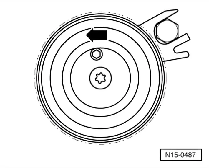
- Turn main drive tensioning roller anti-clockwise to indicated position -arrow- using a hexagon key.
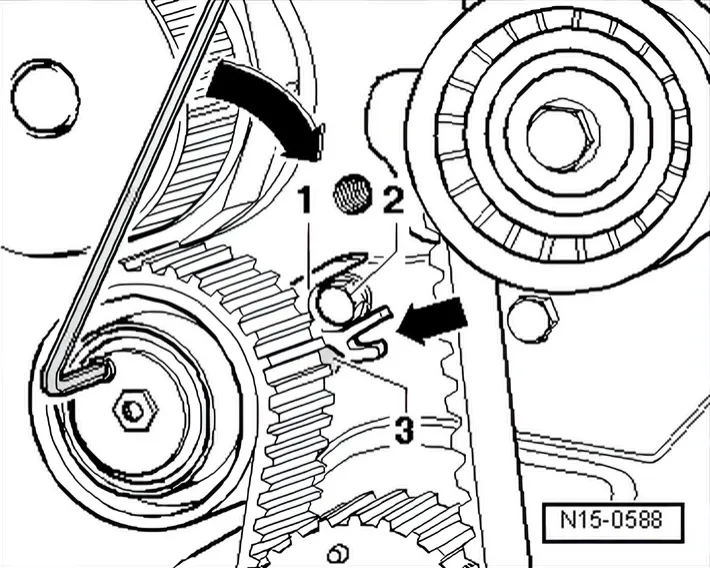
- Tighten securing bolt hand tight. The cut-out in the base plate -1- must engage over securing bolt -2-.
- Then tension toothed belt by turning tensioning roller in direction of arrow until indicator -3- aligns with notch in base plate -arrow-.
- Tighten clamping nut on tensioning roller. Specified torque: 20 Nm
- Remove tool from camshaft pulleys.
- Turn crankshaft two turns in engine direction of rotation until it is again at top dead centre No. 1 cylinder.
- Check toothed belt adjustment and position of tensioning roller.
- Tension both toothed belts again if necessary.
- Refit lower toothed belt guard.
- Refit crankshaft pulley. Observe the following:
- The belt pulley and the toothed belt pulley securing bolt must be renewed.
- When installing belt pulley, observe fixing arrangement to toothed belt pulley.
- Tightening procedure for the new oiled bolt: ⇒ 2.4 Poly V-belt pulley securing bolt tightening procedure
- Fit engine bracket to cylinder head. Specified torque: 50 Nm
- Install poly V-belt tensioning element again on vehicles with an air conditioning system.
- Install engine assembly mounting. Torque setting ⇒ 1.5 Assembly mountings.
- Install lower part of toothed belt guard.
- Install poly V-belt ⇒ 1.4 Removing and installing poly-V belt.
- Install front right wheel housing liner: ⇒ General body repairs, exterior; Rep. gr. 66; Removing and installing wheel housing liner.
- Install engine splash protection.
- Secure coolant expansion tank.