
1.4 TSI engine (EA211) · Mixture preparation – injection · Injection system
Overview of fitting locations - injection system
⇒ 1.1.1 Overview of fitting locations - engine compartment, vehicles with Active Cylinder Management
⇒ 1.1.2 Overview of fitting locations - engine compartment, exhaust side with toothed belt pulley
⇒ 1.1.3 Engine (from above), vehicles with Active Cylinder Management
⇒ 1.1.4 Overview of fitting locations - front view of engine
⇒ 1.1.5 Overview of fitting locations - rear view of engine
1.1.1 Overview of fitting locations - engine compartment, vehicles with Active Cylinder Management
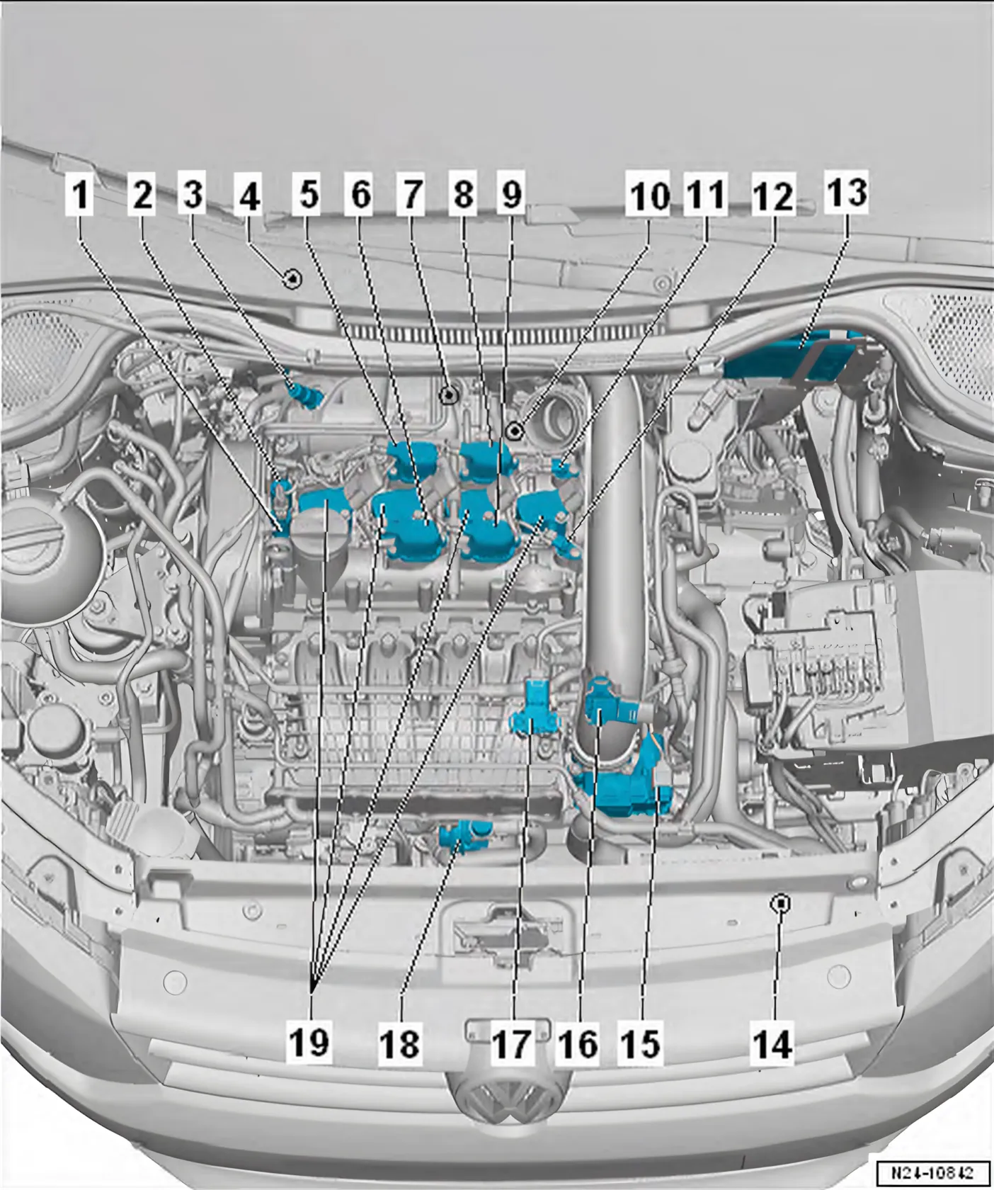
- 1 Inlet camshaft control valve
- 1 N205-
- 2 Exhaust camshaft control valve 1 - N318-
- 3 Lambda probe 1 before catalytic converter - GX10-
- Consisting of
Lambda probe - G39-
Lambda probe heater - Z19-
- Removing and installing ⇒ 8.2 Removing and installing Lambda probe
- 4 Lambda probe 1 after catalytic converter - GX7-
- Consisting of
Lambda probe after catalytic converter - G130-
Lambda probe 1 heater after catalytic converter - Z29-
- Removing and installing ⇒ 8.2 Removing and installing Lambda probe
- 5 Exhaust cam actuator for cylinder 2 - N587-
- Removing and installing ⇒ 3.8 Removing and installing cam actuators
- 6 Exhaust cam actuator for cylinder 3 - N595-
- Removing and installing ⇒ 3.8 Removing and installing cam actuators
- 7 Charge air pressure controller - V465-
- Removing and installing ⇒ 1.3 Removing and installing charge pressure positioner V465
- 8 Inlet cam actuator for cylinder 2 - N583-
- Removing and installing ⇒ 3.8 Removing and installing cam actuators
- 9 Inlet cam actuator for cylinder 3 - N591-
- Removing and installing ⇒ 3.8 Removing and installing cam actuators
- 10 Radiator outlet coolant - G62-
- Removing and installing ⇒ 2.8 Removing and installing coolant temperature sender G62
- 11 Hall sender 3 - G300-
- Removing and installing ⇒ 1.4.2 Removing and installing Hall sender 3 G300
- 12 Hall sender - G40-
- Removing and installing ⇒ 1.4.1 Removing and installing Hall sender G40
- 13 Engine control unit - J623-
- Removing and installing ⇒ 6 Engine control unit
- 14 Radiator outlet coolant temperature sender - G83-
- Removing and installing ⇒ 2.9 Removing and installing radiator outlet coolant temperature sender G83
- 15 Throttle valve module - GX3-
- Throttle valve module - GX3- consists of
- Throttle valve module - J338-
- Throttle valve drive for electronic power control - G186-
- Throttle valve drive angle sender 1 for electronic power control - G187-
- Throttle valve drive angle sender 2 for electronic power control - G188-
- Removing and installing ⇒ 4.3 Removing and installing throttle valve module GX3
- 16 Charge air pressure sender - GX26-
- Consisting of
Charge pressure sender - G31-
Intake air temperature sender - G42-
- Assembly overview ⇒ 2.1 Assembly overview - charge air system
- Removing and installing ⇒ 2.3 Removing and installing charge pressure sender GX26
- 17 Intake manifold sender - GX9-
- Consisting of
Intake air temperature sender 2 - G299-
Intake manifold pressure sender - G71-
- Assembly overview ⇒ 4.1 Assembly overview - intake manifold
- Removing and installing ⇒ 5.3 Removing and installing intake manifold sender GX9
- 18 Charge air cooling pump - V188-
- Removing and installing
- 19 Ignition coils with output stages
- Ignition coil 1 with output stage - N70-
- Ignition coil 2 with output stage - N127-
- Ignition coil 3 with output stage - N291-
- Ignition coil 4 with output stage - N292-
- Removing and installing ⇒ 1.2 Removing and installing ignition coils with output stage
1.1.2 Overview of fitting locations - engine compartment, exhaust side with toothed belt pulley
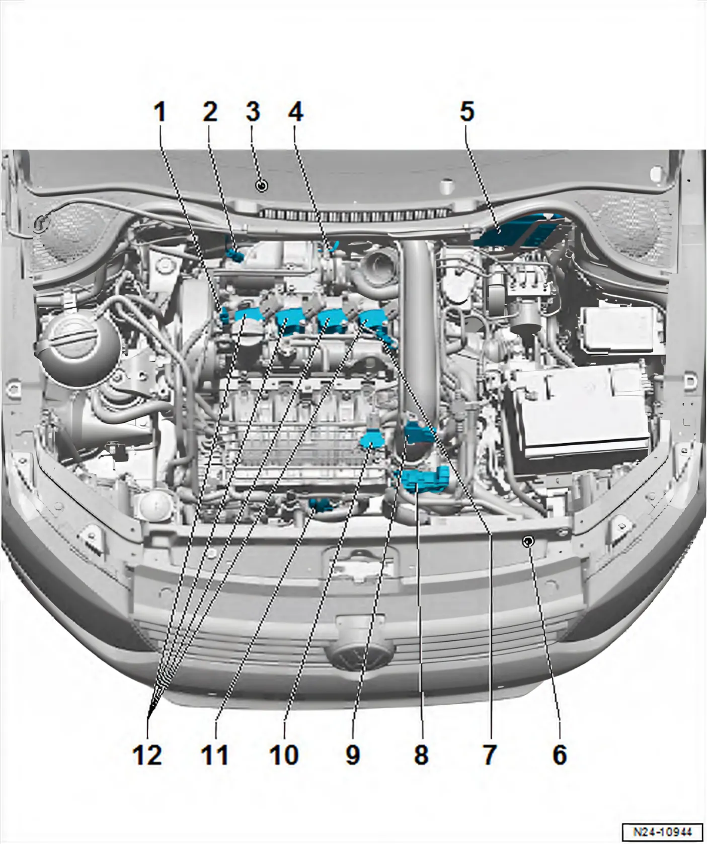
- 1 Inlet camshaft control valve
- 1 N205-
- Removing and installing ⇒ 3.5 Removing and installing camshaft control valve 1 N205
- 2 Lambda probe 1 before catalytic converter - GX10-
- Consisting of
Lambda probe - G39-
Lambda probe heater - Z19-
- Assembly overview ⇒ 8.1 Assembly overview - Lambda probe
- 3 Lambda probe 1 after catalytic converter - GX7-
- Consisting of
Lambda probe after catalytic converter - G130-
Lambda probe 1 heater after catalytic converter - Z29-
- Assembly overview ⇒ 8.1 Assembly overview - Lambda probe
- 4 Charge air pressure controller - V465-
- Removing and installing ⇒ 1.3 Removing and installing charge pressure positioner V465
- 5 Engine control unit - J623-
- Removing and installing ⇒ 6 Engine control unit
- 6 Radiator outlet coolant temperature sender - G83-
- Removing and installing ⇒ 2.9 Removing and installing radiator outlet coolant temperature sender G83
- 7 Hall sender - G40- (camshaft position sender)
- Assembly overview ⇒ 1.1 Assembly overview - ignition system
- 8 Throttle valve module - GX3-
- Consisting of
Throttle valve module - J338-
Throttle valve drive for electronic power control - G186-
Throttle valve drive angle sender 1 for electronic power control - G187-
Throttle valve drive angle sender 2 for electronic power control - G188-
- Assembly overview ⇒ 4.1 Assembly overview - intake manifold
- 9 Charge air pressure sender - GX26-
- Consisting of
Charge pressure sender - G31-
Intake air temperature sender - G42-
- Assembly overview ⇒ 2.1 Assembly overview - charge air system
- 10 Intake manifold sender - GX9-
- Consisting of
Intake air temperature sender 2 - G299-
Intake manifold pressure sender - G71-
- Assembly overview ⇒ 4.1 Assembly overview - intake manifold
- 11 Charge air cooling pump - V188-
- Assembly overview ⇒ 2.2 Assembly overview - electric coolant pump
- 12 Ignition coils with output stages
- Ignition coil 1 with output stage - N70-
- Ignition coil 2 with output stage - N127-
- Ignition coil 3 with output stage - N291-
- Ignition coil 4 with output stage - N292-
- Removing and installing ⇒ 1.2 Removing and installing ignition coils with output stage
1.1.3 Engine (from above), vehicles with Active Cylinder Management
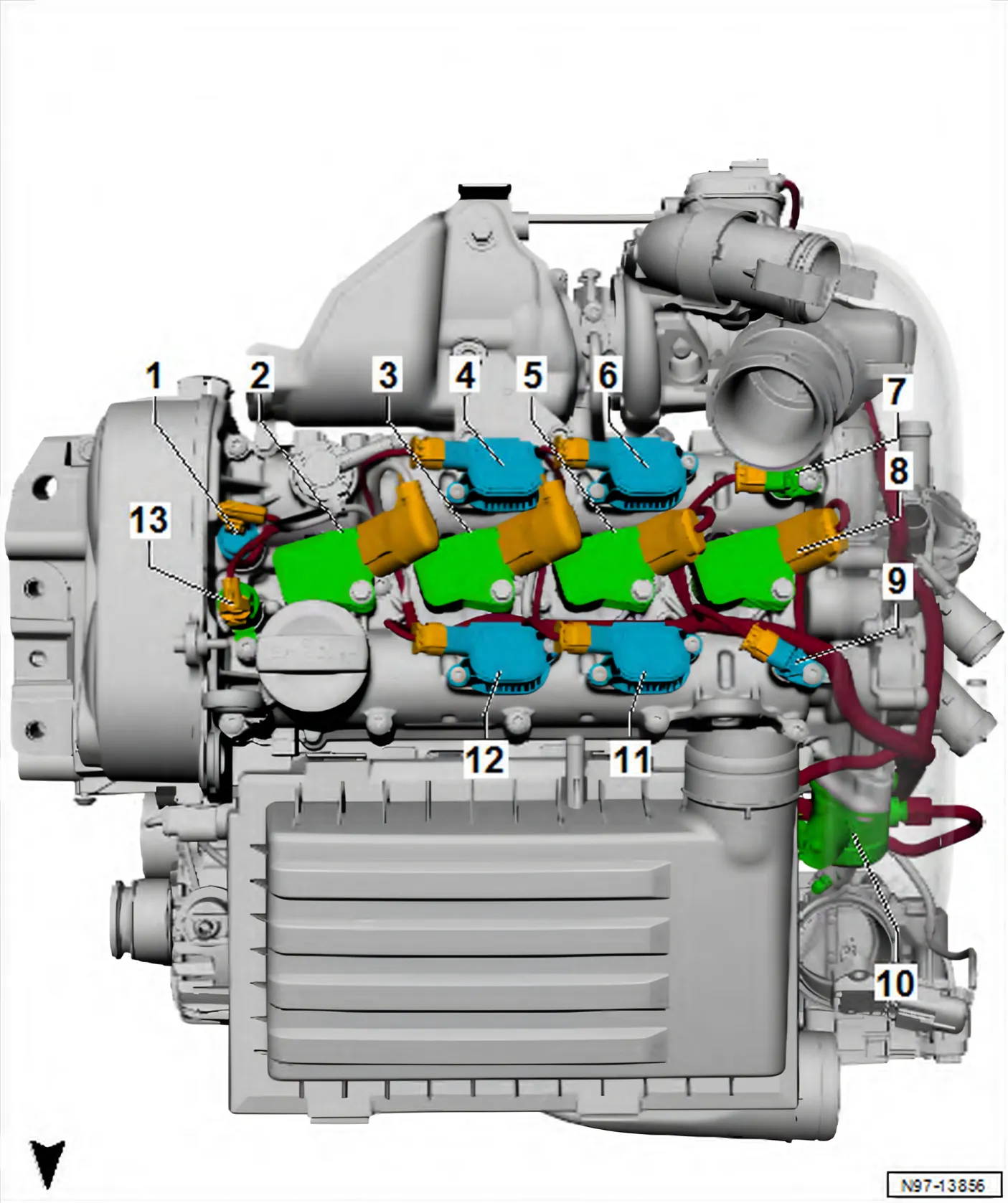
- 1 Exhaust camshaft control valve 1 - N318-
- 2 Ignition coil 1 with output stage - N70-
- Removing and installing ⇒ 1.2 Removing and installing ignition coils with output stage
- 3 Ignition coil 2 with output stage - N127-
- Removing and installing ⇒ 1.2 Removing and installing ignition coils with output stage
- 4 Exhaust cam actuator for cylinder 2 - N587-
- Removing and installing ⇒ 3.8 Removing and installing cam actuators
- 5 Ignition coil 3 with output stage - N291-
- Removing and installing ⇒ 1.2 Removing and installing ignition coils with output stage
- 6 Exhaust cam actuator for cylinder 3 - N595-
- Removing and installing ⇒ 3.8 Removing and installing cam actuators
- 7 Hall sender 3 - G300-
- Removing and installing ⇒ 1.4.2 Removing and installing Hall sender 3 G300
- 8 Ignition coil 4 with output stage - N292-
- Removing and installing ⇒ 1.2 Removing and installing ignition coils with output stage
- 9 Hall sender - G40-
- Removing and installing ⇒ 1.4.1 Removing and installing Hall sender G40
- 10 High-pressure pump
- Assembly overview ⇒ 7.1 Assembly overview - high-pressure pump
- Removing and installing ⇒ 7.2 Removing and installing high-pressure pump
- 11 Inlet cam actuator for cylinder 2 - N583-
- Removing and installing ⇒ 3.8 Removing and installing cam actuators
- 12 Inlet cam actuator for cylinder 3 - N591-
- Removing and installing ⇒ 3.8 Removing and installing cam actuators
- 13 Inlet camshaft control valve 1 - N205-
1.1.4 Overview of fitting locations - front view of engine
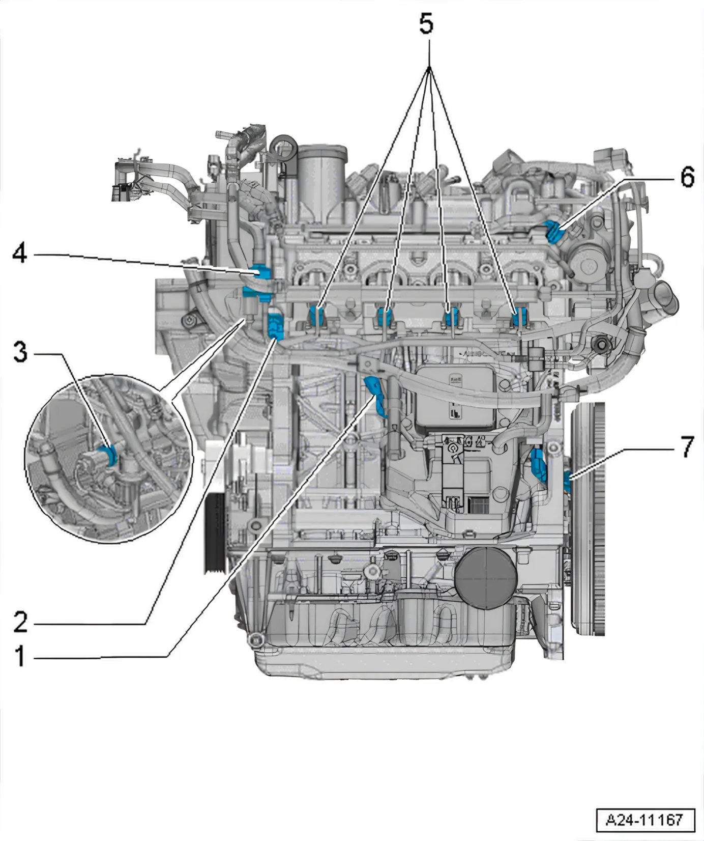
- 1 Knock sensor 1 - G61-
- Assembly overview ⇒ 1.1 Assembly overview - ignition system
- 2 Oil pressure switch for reduced oil pressure - F378-
- 3 Fuel pressure sender - G247-
- Assembly overview ⇒ 2.1 Assembly overview - fuel rail with injectors
- 4 Activated charcoal filter solenoid valve 1 - N80-
- 5 Injectors
- Injector, cylinder 1 - N30-
- Injector, cylinder 2 - N31-
- Injector, cylinder 3 - N32-
- Injector, cylinder 4 - N33-
- Assembly overview ⇒ 2.1 Assembly overview - fuel rail with injectors
- 6 Fuel pressure regulating valve - N276-
- On high-pressure pump
- Assembly overview ⇒ 7.1 Assembly overview - high-pressure pump
- 7 Engine speed sender - G28-
- Assembly overview ⇒ 1.1 Assembly overview - ignition system
1.1.5 Overview of fitting locations - rear view of engine
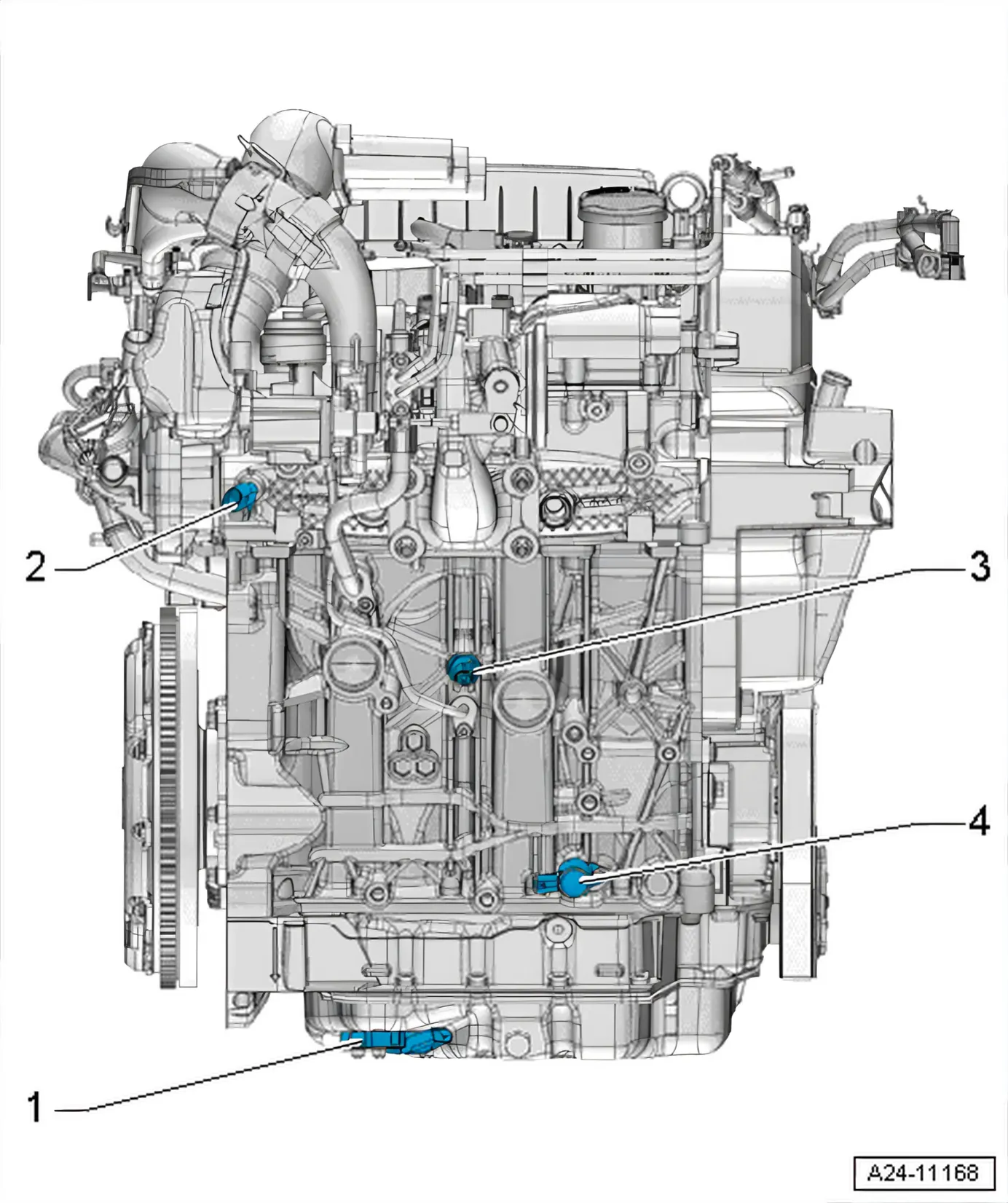
- 1 Oil level and oil temperature sender - G266-
- Removing and installing ⇒ 1.6 Removing and installing oil level and oil temperature sender G266
- 2 Radiator outlet coolant - G62-
- Removing and installing ⇒ 2.8 Removing and installing coolant temperature sender G62
- 3 Oil pressure switch - F1-
- Removing and installing ⇒ 4.2 Removing and installing oil pressure switch F1
- 4 Valve for oil pressure control - N428-
- Removing and installing ⇒ 4.5 Removing and installing oil pressure regulating valve N428