
1.4 TSI engine (EA211) · Mixture preparation – injection · High-pressure pump
High-pressure pump – assembly overview and fastening
⇒ 7.1.1 Assembly overview - high-pressure pump, version 1
⇒ 7.1.2 Assembly overview - high-pressure pump, version 2
⇒ 7.1.3 Assembly overview - high-pressure pump, version 3
7.1.1 Assembly overview - high-pressure pump, version 1
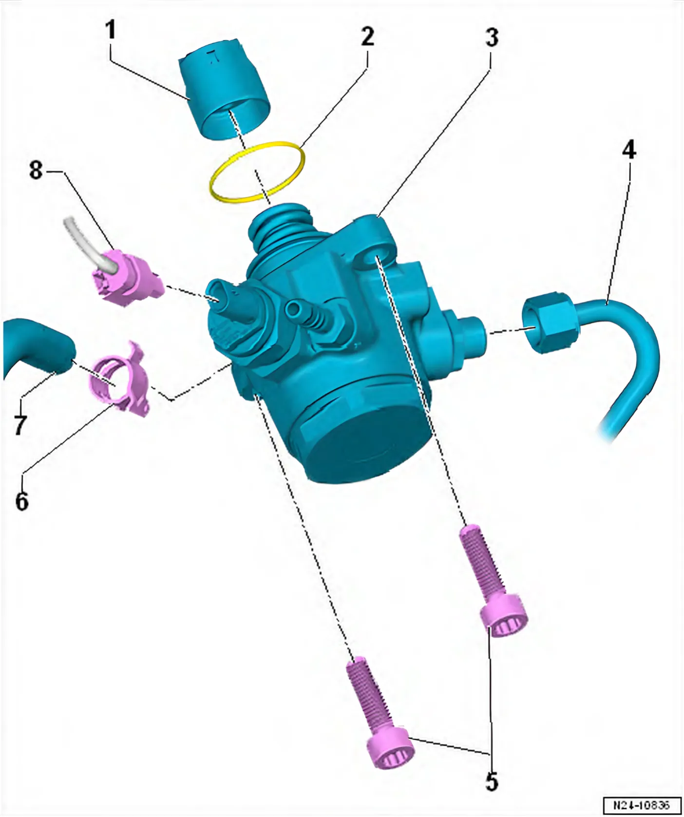
- 1 Roller tappet
- When installing lubricate lightly with clean engine oil
- 2 O-ring
- Renew
- Coat lightly with clean engine oil when installing.
- 3 High-pressure pump
- With fuel pressure regulating valve - N276-.
- Do not dismantle.
- Removing and installing ⇒ 7.2 Removing and installing high-pressure pump
- 4 High-pressure pipe
- Renew after removal
- Unions must be free of damage
- Do not alter shape.
- Removing and installing ⇒ 7.3 Removing and installing high-pressure pipe
- Lubricate thread of union nuts with clean engine oil
- 16 Nm +45°
- 5 Bolt
- M8x32
- Renew
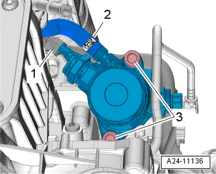
- Specified torque and tightening sequence ⇒ 7.1.1 Assembly overview - high-pressure pump, version 1
- 6 Hose clamp
- 7 Fuel supply line
- 8 Electrical connector
High-pressure pump - specified torque and tightening sequence
To prevent flange of high-pressure pump from being deformed during installation, install high-pressure pump as follows:
- Tighten new bolt in stages as follows:
| Stage | M8 bolts | Specified torque/turning further angle |
|---|---|---|
| 1. | -3- | Screw in by hand as far as stop |
| 2. | -3- | Tighten one turn alternately until flange of high-pressure pump makes contact with camshaft housing |
| 3. | -3- | 20 Nm |
| 4. | -3- | Turn 90° further |
7.1.2 Assembly overview - high-pressure pump, version 2
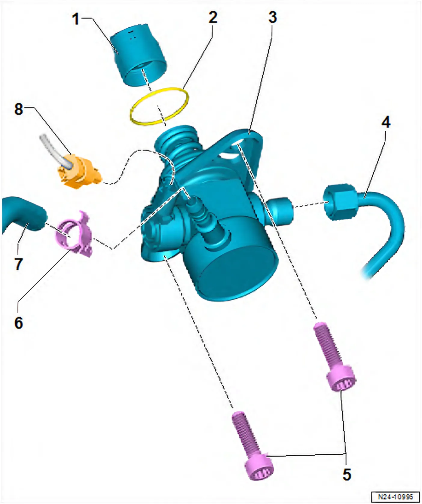
- 1 Roller tappet
- When installing lubricate lightly with clean engine oil
- 2 O-ring
- Renew
- When installing lubricate lightly with clean engine oil
- 3 High-pressure pump
- With fuel pressure regulating valve - N276-.
- Do not dismantle.
- Removing and installing ⇒ 7.2 Removing and installing high-pressure pump
- 4 High-pressure pipe
- Renew
- Removing and installing ⇒ 7.3 Removing and installing high-pressure pipe
- Do not alter shape.
- Unions must be free of damage
- Lubricate thread of union nuts with clean engine oil
- 16 Nm +45°
- 5 Bolt
- M8x25
- Renew
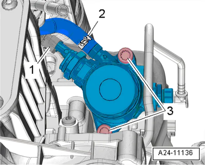
- Specified torque and tightening sequence ⇒ 7.1.2 Assembly overview - high-pressure pump, version 2
- 6 Hose clamp
- 7 Fuel supply line
- 8 Electrical connector
High-pressure pump - specified torque and tightening sequence
To prevent flange of high-pressure pump from being deformed during installation, install high-pressure pump as follows:
- Tighten new bolt in stages as follows:
| Stage | M8 bolts | Specified torque/turning further angle |
|---|---|---|
| 1. | -3- | Screw in by hand as far as stop |
| 2. | -3- | Tighten one turn alternately until flange of high-pressure pump makes contact with camshaft housing |
| 3. | -3- | 20 Nm |
| 4. | -3- | Turn 90° further |
7.1.3 Assembly overview - high-pressure pump, version 3
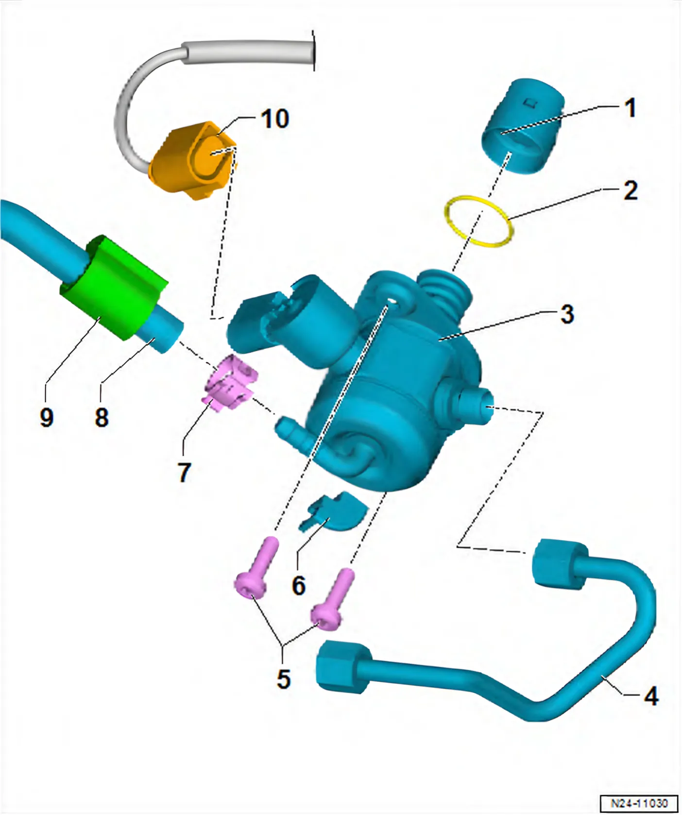
- 1 Roller tappet
- When installing lubricate lightly with clean engine oil
- 2 O-ring
- Renew
- Coat lightly with clean engine oil when installing.
- 3 High-pressure pump
- With fuel pressure regulating valve - N276-.
- Do not dismantle.
- Removing and installing ⇒ 7.2 Removing and installing high-pressure pump
- 4 High-pressure pipe
- Renew after removal
- Unions must be free of damage
- Do not alter shape.
- Removing and installing ⇒ 7.3 Removing and installing high-pressure pipe
- Lubricate thread of union nuts with clean engine oil
- 16 Nm +45°
- 5 Bolt
- M6x22
- Renew
- Specified torque and tightening sequence ⇒ 7.1.3 Assembly overview - high-pressure pump, version 3
- 6 Clip
- 7 Hose clamp
- 8 Fuel supply line
- 9 Serrated washer
- Fit directly behind spring-type clip
- As shown in illustration, cap points in direction of fuel pressure regulating valve - N276-
- 10 Electrical connector
High-pressure pump - specified torque and tightening sequence
To prevent flange of high-pressure pump from being deformed during installation, install high-pressure pump as follows:
- Tighten new bolt in stages as follows:
| Stage | M6 bolts | Specified torque/turning further angle |
|---|---|---|
| 1. | -3- | Screw in by hand as far as stop |
| 2. | -3- | Tighten one turn alternately until flange of high-pressure pump makes contact with camshaft housing |
| 3. | -3- | 8 Nm |
| 4. | -3- | Turn 90° further |