
1.4 TSI engine (EA211) · Turbocharging/supercharging · Exhaust turbocharger
Removing and installing charge pressure positioner - V465-
⇒ 1.3.1 Removing and installing charge pressure positioner V465, version 1
⇒ 1.3.2 Removing and installing charge pressure positioner V465, version 2
1.3.1 Removing and installing charge pressure positioner - V465-, version 1
Removing
- Switch off ignition.
- Remove noise insulation ⇒ General body repairs, exterior; Rep. gr. 66; Noise insulation; Assembly overview - noise insulation.
- Remove heat shield for drive shaft ⇒ Running gear, axles, steering; Rep. gr. 40; Drive shaft; Removing and installing drive shaft heat shield.
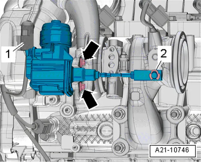
- Disconnect electrical connector -1-.
- Remove securing clip -2-.
- Remove bolts -arrows- and detach charge pressure positioner
- V465-.
Installing
Install in reverse order of removal, observing the following:
Always renew securing bolts and the securing clip.
Charge pressure positioner without adjustable linkage:
- Adapt engine control unit - J623- to charge pressure positioner
- V465- using ⇒ Vehicle diagnostic tester; “Guided functions”.
Charge pressure positioner with adjustable linkage:
- Fit thread of charge pressure positioner -V465- at central position in joint element.
- Adjust charge air pressure controller - V465- : ⇒ Vehicle diag‐
nostic tester Select 01 - Adjust charge air pressure controller V465 in Guided functions.
- Adjust to specified value by turning linkage. For specified value, see ⇒ Vehicle diagnostic tester.
- Tighten lock nut to 6 Nm and secure with sealing paint.
Torque settings
- ⇒ 1.1.1 Assembly overview - turbocharger, version 1
- ⇒ Running gear, axles, steering; Rep. gr. 40; Drive shaft; Assembly overview - drive shaft
1.3.2 Removing and installing charge pressure positioner - V465-, version 2
Removing
- Switch off ignition.
- Remove noise insulation ⇒ General body repairs, exterior; Rep. gr. 66; Noise insulation; Assembly overview - noise insulation.
- Remove heat shield for drive shaft ⇒ Running gear, axles, steering; Rep. gr. 40; Drive shaft; Removing and installing drive shaft heat shield.
- Remove resonator for intake air ⇒ 3.3 Removing and installing resonator for intake air.
- Remove air pipe ⇒ 2.5 Removing and installing air intake pipe.
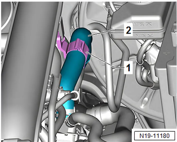
- Open hose clip -1- and push coolant hose -2- to one side.
- Unscrew bolts -arrows- and remove crankcase breather hose.
- Remove connection for turbocharger ⇒ 1.4 Removing and installing connection for turbocharger.
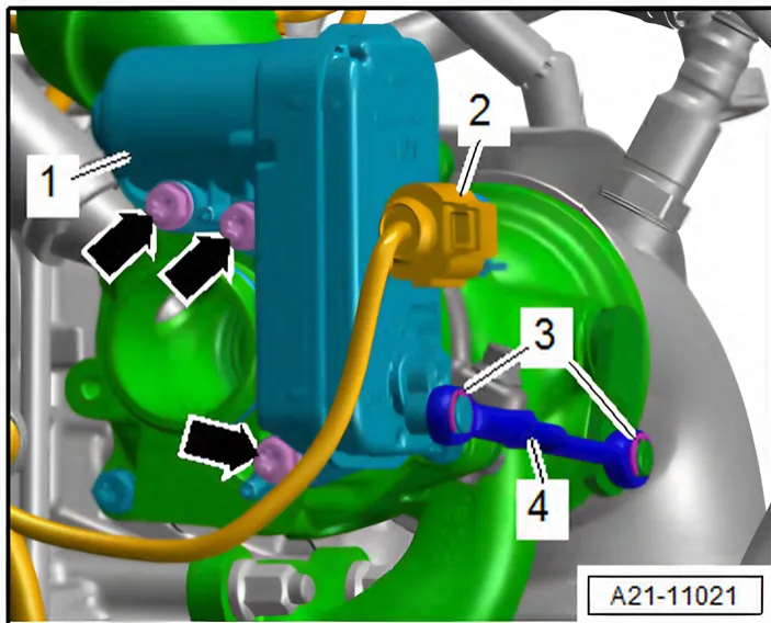
- Pull off securing clips -3-, and remove operating lever -4-.
- Unscrew bolts -arrows-.
- Disconnect connector -2-, and remove charge pressure positioner - V465- -1-.
Installing
Install in reverse order of removal, observing the following:
Always renew securing bolts and the securing clip.
Renew O-rings after removal.
Before installing, lightly moisten O-rings with clean engine oil.
Charge air pressure controller without adjustable linkage
- Adapt engine control unit - J623- to charge pressure positioner
- V465- using ⇒ Vehicle diagnostic tester; “Guided functions”.
Charge air pressure controller with adjustable linkage
- Fit thread of charge pressure positioner -V465- at central position in joint element.
- Adjust charge air pressure controller - V465- : ⇒ Vehicle diag‐
| 01 - Adjust charge air pressure | ||
| in | Guided functions | . |
- Adjust to specified value by turning linkage. For specified value, see ⇒ Vehicle diagnostic tester.
- Tighten lock nut to 6 Nm and secure with sealing paint.
Torque settings
- ⇒ 1.1.2 Assembly overview - turbocharger, version 2
- ⇒ Running gear, axles, steering; Rep. gr. 40; Drive shaft; Assembly overview - drive shaft