
1.4 TSI engine (EA211) · Cylinder head, valve gear · Valve gear
Removing and installing camshaft adjuster
⇒ 3.3.1 Removing and installing inlet side camshaft adjuster, exhaust side with camshaft adjuster
⇒ 3.3.3 Removing and installing camshaft adjuster for exhaust camshaft
3.3.1 Removing and installing inlet side camshaft adjuster, exhaust side with camshaft adjuster
Special tools and workshop equipment required
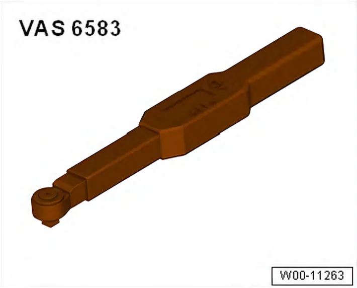
- Torque wrench - VAS 6583-
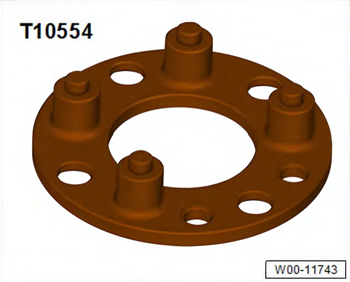
- Counter-hold tool - T10554/1-
- Knurled screws - T10554/2- (not illustrated)
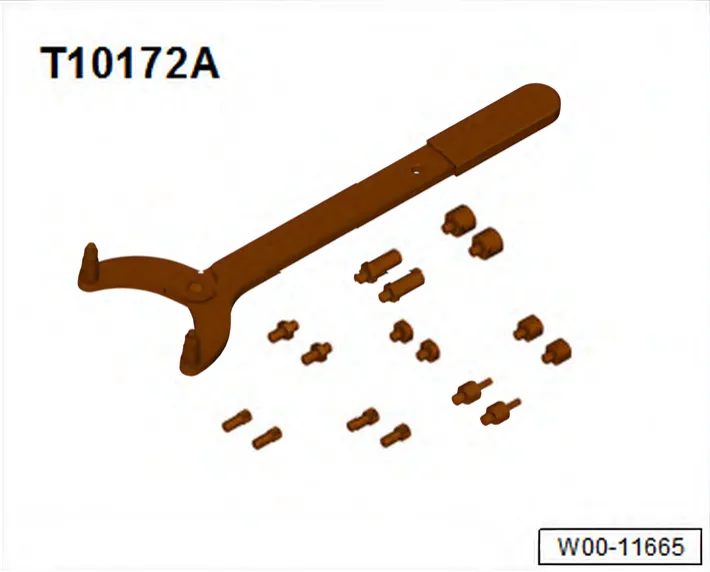
- Counter-hold tool - T10172A-
Preparing tools
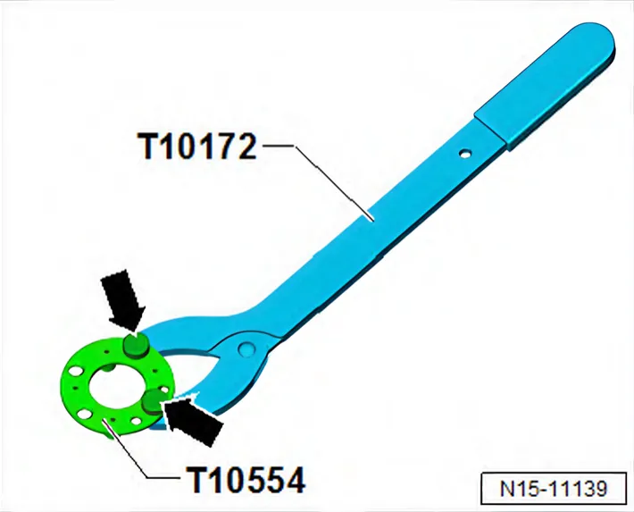
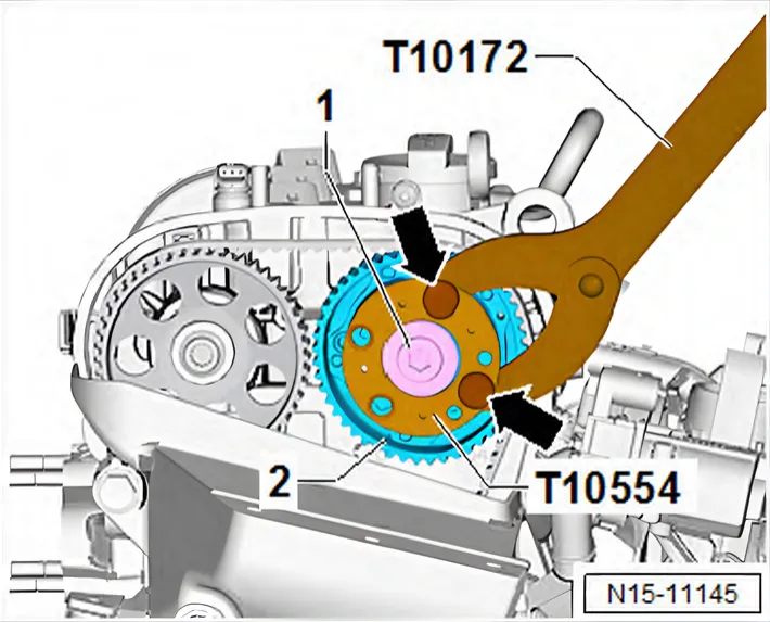
- Bolt on counter-hold tool - T10172- and counter-hold tool - T10554/1- using knurled screws - T10554/2- -arrows-.
Procedure
Removing
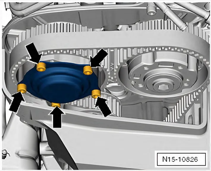
- Unscrew bolts -arrows- and remove cover from camshaft adjuster for exhaust camshaft.
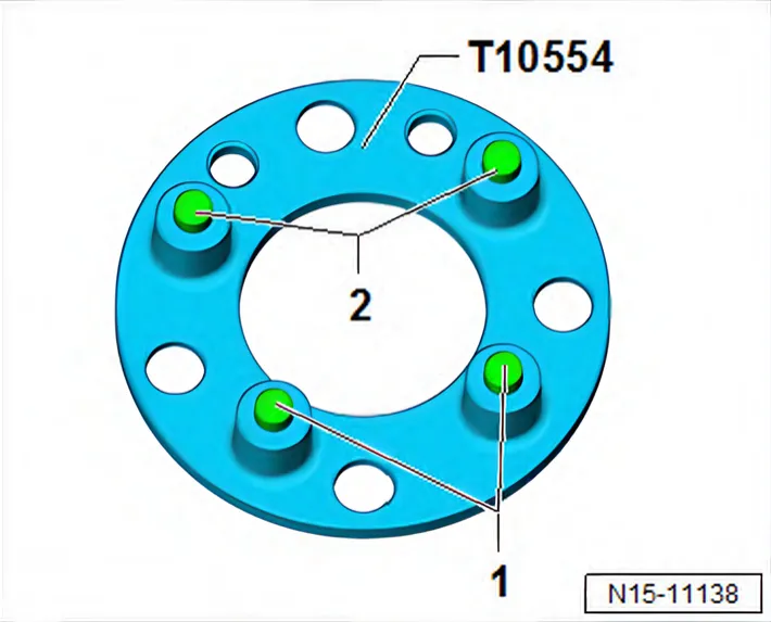
Fitting counter-hold tool - T10554-
- The contours of pins -1- and -2- of counter-hold tool - T10554/1- are not distributed evenly on the bolt circle.
- They correspond to the contour of the bolt circle in the camshaft adjuster.
| NOTICE |
Risk of damage to camshaft caused by improper handling.
- Never use the camshaft clamp for counter holding.
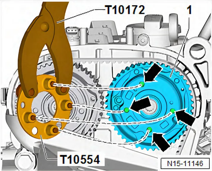
Loosening camshaft adjuster on inlet side:
- Set piston in cylinder no. 1 to TDC position ⇒ 4.7 Setting piston to TDC position.
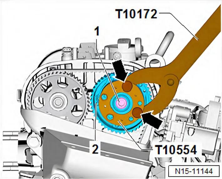
- Fit counter-hold tool - T10554- with counter-hold tool - T10172- to camshaft pulley -1- as shown in illustration.
- The pins must be inserted properly into holes -arrows-.
- Fit counter-hold tool - T10554- so that it rests flat against camshaft adjuster -1-.
- Hold camshaft in position using counterhold tool - T10554- and counterhold tool - T10172-.
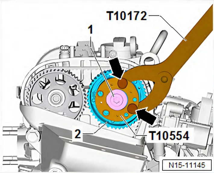
- Loosen plug -1-, and unscrew it.
- Fit counter-hold tool - T10554- with counter-hold tool - T10172- again, to loosen securing bolt -1- of camshaft adjuster.
- Loosen bolt -1- of camshaft adjuster -2-.
- Loosen securing bolt of camshaft adjuster on exhaust side ⇒ 3.3.3 Removing and installing camshaft adjuster for exhaust camshaft.
Removing camshaft adjuster of inlet camshaft:
- Detach toothed belt from camshafts.
- Unscrew securing bolt -1- of camshaft adjuster, and remove camshaft adjuster -2-.
Installing
- Camshafts are located in “TDC” position.
- The camshaft pulleys are properly aligned with each other.
- Crankshaft is in “TDC position”.
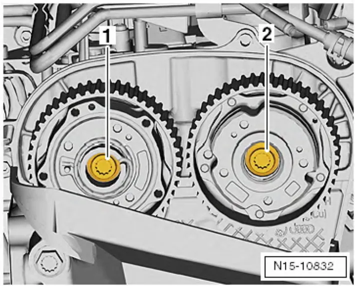
- Renew bolts -1- and -2- for both camshaft adjusters and screw them in onto stop.
- It should just be possible to turn camshaft pulleys on camshafts but no rocking is permissible.
- Fit toothed belt onto camshafts ⇒ 2.7 Removing toothed belt from camshaft.
- Adjust valve timing ⇒ 2.6 Adjusting valve timing.
Tightening camshaft adjuster of inlet camshaft to specified initial torque
- Before pre-tightening, unscrew locking pin - T10340-.
- Hold inlet camshaft in position using counter-hold tool - T10554- and counter-hold tool - T10172-.
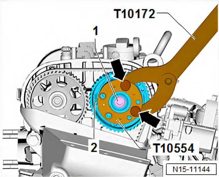
- Pre-tighten bolt -1- to specified pre-tightening torque in two stages.
| Stage | Securing bolt for camshaft adjuster, inlet side | Torque setting |
|---|---|---|
| 1. | -1- | 18 Nm |
| 2. | -1- | 50 Nm |
- Hold exhaust camshaft in position using counterhold tool - T10554- and counterhold tool - T10172-.
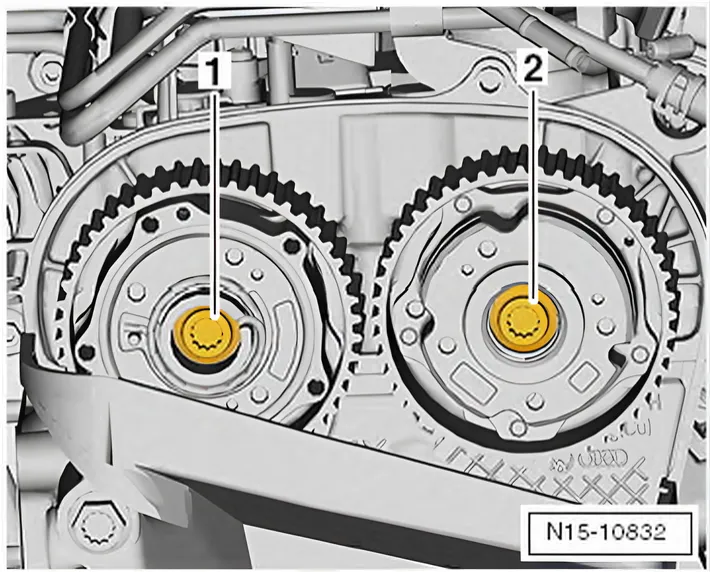
- Pre-tighten bolt -1- to specified pre-tightening torque in two stages.
| Stage | Securing bolt for camshaft adjuster, exhaust side | Torque setting |
|---|---|---|
| 1. | -1- | 18 Nm |
| 2. | -1- | 50 Nm |
Tightening camshaft adjuster to specified final torque
- Tighten bolt -1- for camshaft adjuster to final specified torque.
| Stage | Securing bolt for camshaft adjuster, inlet side | Angle to turn bolts |
| 1. | -1- | 135° |
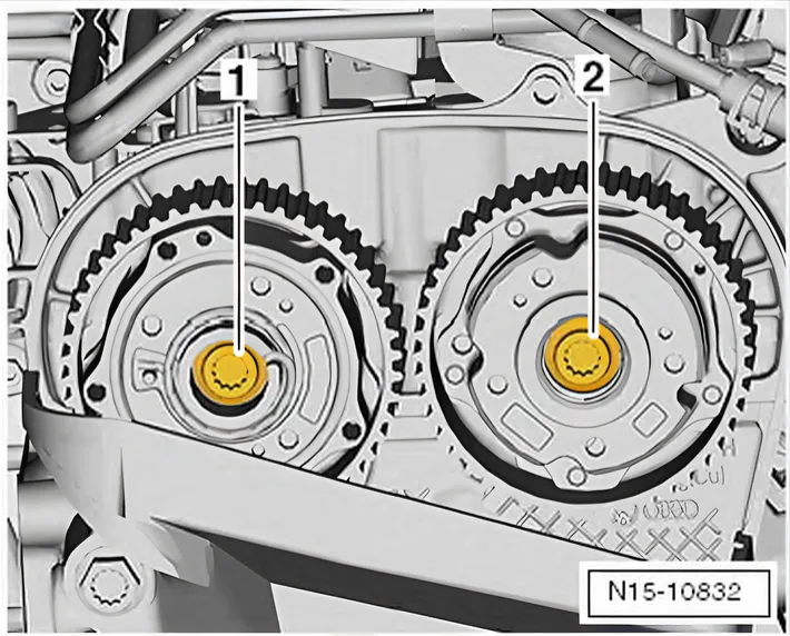
- Tighten securing bolt for camshaft adjuster on exhaust side -1- to final torque setting.
| Stage | Securing bolt for camshaft adjuster | Angle to turn bolts |
| 1. | -1- | 135° |
- Screw in plug -1-, and tighten it to specified torque.
- Hold inlet camshaft in position using counter-hold tool - T10554- and counter-hold tool - T10172-.
| Stage | Plug for camshaft adjuster | Torque setting |
| 1. | -1- | 20 Nm |
Installing
Assembly is carried out in reverse sequence; note the following:
Torque settings
- ⇒ 2.2 Assembly overview - toothed belt
- ⇒ 2.1 Assembly overview - cylinder block, gearbox end
- ⇒ 1.2 Assembly overview - camshaft housing
- ⇒ 3.1 Assembly overview - crankcase breather system
- ⇒ 2.1 Assembly overview - charge air system
- ⇒ 3.1 Assembly overview - valve gear
- ⇒ 1.1 Assembly overview - turbocharger
- ⇒ 2.1 Assembly overview - toothed belt cover
3.3.2 Removing and installing inlet side camshaft adjuster, exhaust side with toothed belt sprocket
Special tools and workshop equipment required
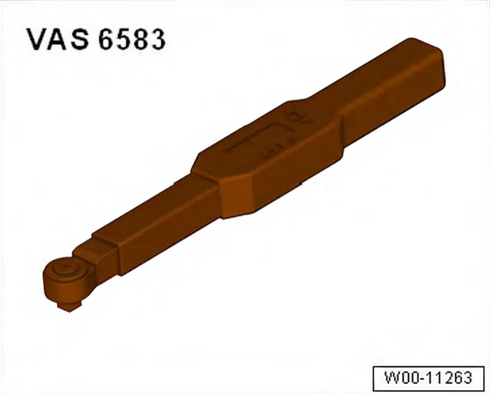
- Torque wrench - VAS 6583-
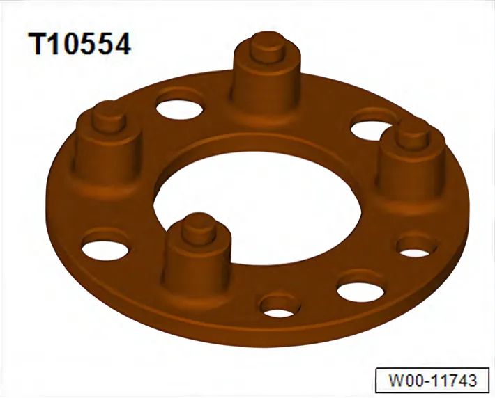
- Counter-hold tool - T10554/1-
- Knurled screws - T10554/2- (not illustrated)
- Counter-hold tool - T10172A-
Preparing tools
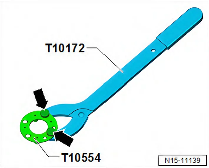
- Bolt on counter-hold tool - T10172- and counter-hold tool - T10554/1- using knurled screws - T10554/2- -arrows-.
Procedure
Removing
Fitting counter-hold tool - T10554-
- The contours of pins -1- and -2- of counter-hold tool - T10554/1- are not distributed evenly on the bolt circle.
- They correspond to the contour of the bolt circle in the camshaft adjuster.
| NOTICE |
Risk of damage to camshaft caused by improper handling.
- Never use the camshaft clamp for counter holding.
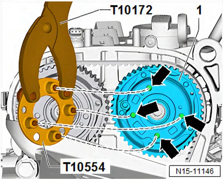
Loosening camshaft adjuster on inlet side:
- Set piston in cylinder no. 1 to TDC position ⇒ 4.7 Setting piston to TDC position.
- Fit counter-hold tool - T10554- with counter-hold tool - T10172- to camshaft pulley -1- as shown in illustration.
- The pins must be inserted properly into holes -arrows-.
- Fit counter-hold tool - T10554- so that it rests flat against camshaft adjuster -1-.
- Hold inlet camshaft in position using counter-hold tool - T10554- and counter-hold tool - T10172-.
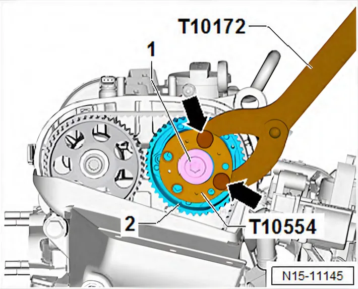
- Loosen plug -1-, and unscrew it.
- Fit counter-hold tool - T10554- with counter-hold tool - T10172- again, to loosen securing bolt -1- of camshaft adjuster.
- Loosen bolt -1- of camshaft adjuster -2-.
- Loosen securing bolt of toothed belt pulley on exhaust side ⇒ 3.4 Removing and installing toothed belt pulley.
Removing camshaft adjuster of inlet camshaft:
- Detach toothed belt from camshafts.
- Unscrew securing bolt -1- of camshaft adjuster, and remove camshaft adjuster -2-.
- Use a cleaning cloth to remove engine oil from camshaft and camshaft housing.
Installing
- Camshafts are located in “TDC” position.
- Camshaft pulleys are properly aligned.
- Crankshaft is in “TDC position”.
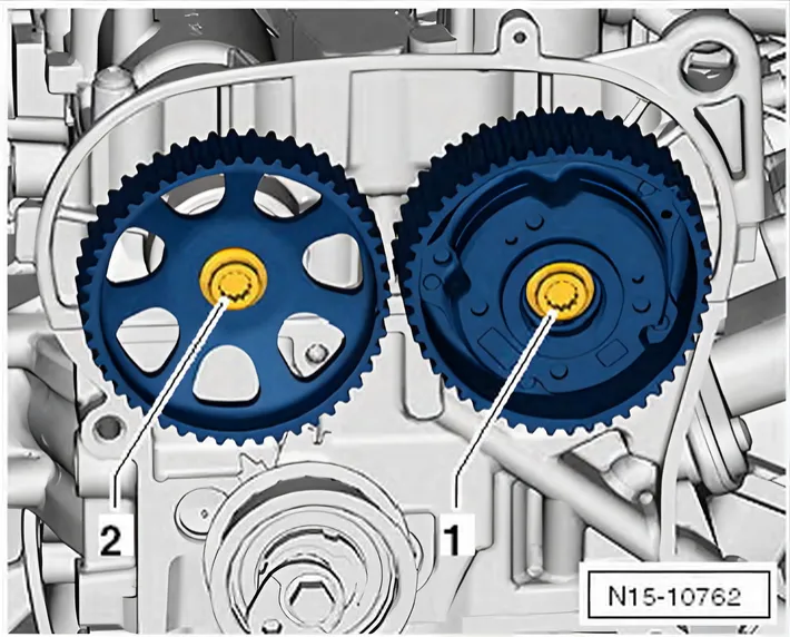
- Renew bolt -1- for camshaft adjuster on inlet side, and screw it in to stop by hand.
- Renew bolt -2- for toothed belt pulley on exhaust side, and screw it in to stop by hand.
- It should just be possible to turn camshaft pulleys on camshafts but no rocking is permissible.
- Fit toothed belt onto camshafts ⇒ 2.7 Removing toothed belt from camshaft.
- Adjust valve timing ⇒ 2.6 Adjusting valve timing.
Tightening camshaft adjuster of inlet camshaft to specified initial torque
- Before pre-tightening, unscrew locking pin - T10340-.
- Hold inlet camshaft in position using counter-hold tool - T10554- and counter-hold tool - T10172-.
- Pre-tighten bolt -1- to specified pre-tightening torque in two stages.
| Stage | Securing bolt for camshaft adjuster | Torque setting |
|---|---|---|
| 1. | -1- | 18 Nm |
| 2. | -1- | 50 Nm |
- Hold inlet camshaft in position using counter-hold tool - T10172- and adapter - T10172/1-.
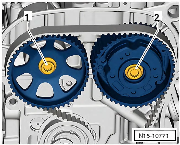
- Pre-tighten bolt -1- to specified pre-tightening torque in two stages.
| Stage | Securing bolt for toothed belt pulley | Torque setting |
|---|---|---|
| 1. | -1- | 18 Nm |
| 2. | -1- | 50 Nm |
Tightening camshaft adjuster of inlet camshaft to specified final torque
- Screw locking pin - T10340- back in.
- Tighten bolt -1- for camshaft adjuster to final specified torque.
| Stage | Securing bolt for camshaft adjuster | Angle to turn bolts |
| 1. | -1- | 135° |
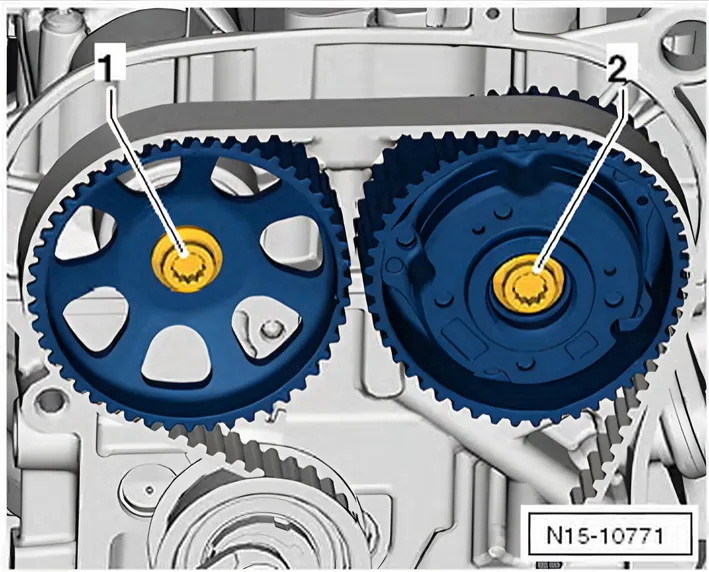
- Tighten securing bolt for toothed belt pulley on exhaust side to final specified torque.
| Stage | Securing bolt for toothed belt pulley | Angle to turn bolts |
| 1. | -1- | 90° |
- Screw in plug -1-, and tighten it to specified torque.
- Hold inlet camshaft in position using counter-hold tool - T10172A- and counter-hold tool - T10554-.
| Stage | Plug for camshaft adjuster | Torque setting |
| 1. | -1- | 20 Nm |
Installing
Assembly is carried out in reverse sequence; note the following:
Torque settings
- ⇒ 2.1 Assembly overview - toothed belt cover
- ⇒ 2.2 Assembly overview - toothed belt
- ⇒ 1.2 Assembly overview - camshaft housing
- ⇒ 3.1 Assembly overview - crankcase breather system
- ⇒ 2.1 Assembly overview - assembly mountings
- ⇒ 1.1 Assembly overview - poly V-belt drive
- ⇒ Electrical system; Rep. gr. 27; Alternator; Exploded view
- alternator
- ⇒ 3.1 Assembly overview - coolant pipes
- ⇒ 2.1 Assembly overview - coolant pump, thermostat
- ⇒ 2.1 Assembly overview - charge air system
3.3.3 Removing and installing camshaft adjuster for exhaust camshaft
Special tools for removing and installing the camshaft adjuster of exhaust camshaft
Special tools and workshop equipment required
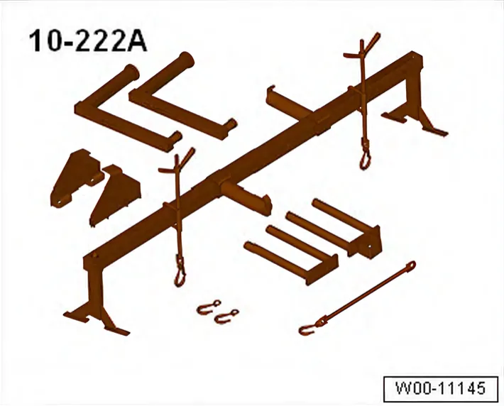
- Support - 10 - 222 A-
- Shackle - 10 - 222 A /12-
- Adapter - 10 - 222 A /18-
- Adapter - 10 - 222 A /29-
- Adapter - T40091/1-
- Adapter - T40091/3-
- Adapter - T40093/3-
- Adapter - T40093/3-6-
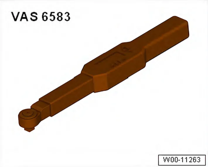
- Torque wrench - VAS 6583-
- Counter-hold tool - T10554/1-
- Knurled screws - T10554/2- (not illustrated)
- Counter-hold tool - T10172A-
Preparing tools
- Bolt on counter-hold tool - T10172- and counter-hold tool - T10554/1- using knurled screws - T10554/2- -arrows-.
Procedure
- Unscrew bolts -arrows- and remove cover from camshaft adjuster for exhaust camshaft.
Fitting counter-hold tool - T10554-
- The contours of pins -1- and -2- of counter-hold tool - T10554/1- are not distributed evenly on the bolt circle.
- They correspond to the contour of the bolt circle in the camshaft adjuster.
| NOTICE |
Risk of damage to camshaft caused by improper handling.
- Never use the camshaft clamp for counter holding.
To adjust valve timing:
- Set piston in cylinder no. 1 to TDC position ⇒ 4.7 Setting piston to TDC position.
Detaching camshaft adjuster on exhaust side:
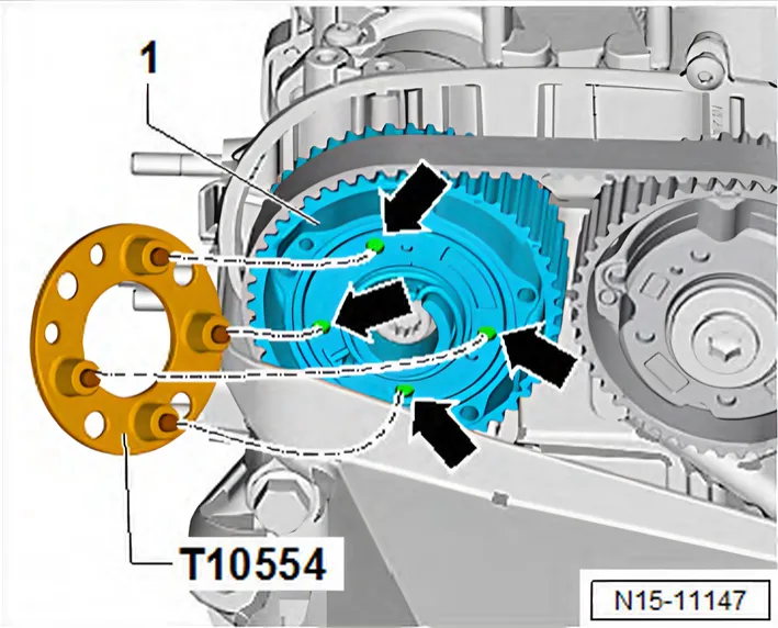
- Insert counterhold - T10554- with counterhold - T10172- in holes -arrows-.
- Fit counter-hold tool - T10554- so that it rests flat against camshaft adjuster -1-.
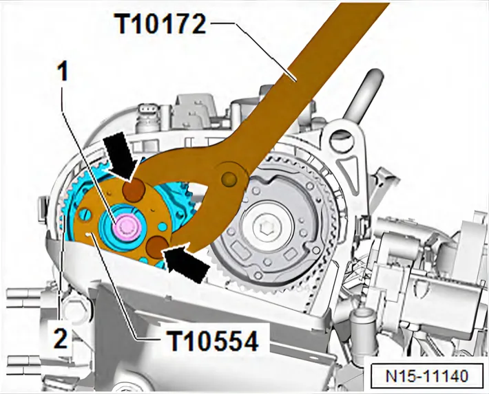
- Hold camshaft pulley -2- in place using counterhold - T10554- and counterhold - T10172-.
- Loosen bolt -1- one turn.
- Loosen securing bolt for camshaft adjuster on inlet side ⇒ 3.3.2 Removing and installing inlet side camshaft adjuster, exhaust side with toothed belt sprocket.
Removing camshaft adjuster of exhaust camshaft:
- Remove engine bracket. ⇒ 1.6 Removing and installing engine support
- Detach toothed belt from camshafts ⇒ 2.7 Removing toothed belt from camshaft.
- Unscrew securing bolt -1- of camshaft adjuster, and remove camshaft adjuster -2-.
- Use a cleaning cloth to remove engine oil from camshaft and camshaft housing.
Installing
- Camshafts are located in “TDC” position.
- The camshaft pulleys are properly aligned with each other.
- Crankshaft is in “TDC position”.
- Renew bolts -1- and -2- for both camshaft adjusters and screw them in onto stop.
- It should just be possible to turn camshaft pulleys on camshafts but no rocking is permissible.
- Fit toothed belt onto camshafts ⇒ 2.7 Removing toothed belt from camshaft.
- Adjusting valve timing ⇒ 2.6 Adjusting valve timing
Camshaft adjuster specified final torque
- Before pre-tightening, unscrew locking pin - T10340-.
- Hold inlet camshaft in position using counter-hold tool - T10554- and counter-hold tool - T10172-.
- Pre-tighten bolt -1- to specified pre-tightening torque in two stages.
| Stage | Securing bolt for camshaft adjuster, inlet side | Torque setting |
|---|---|---|
| 1. | -1- | 18 Nm |
| 2. | -1- | 50 Nm |
- Hold exhaust camshaft in position using counterhold tool - T10554- and counterhold tool - T10172-.
- Pre-tighten bolt -1- to specified pre-tightening torque in two stages.
| Stage | Securing bolt for camshaft adjuster, exhaust side | Torque setting |
|---|---|---|
| 1. | -1- | 18 Nm |
| 2. | -1- | 50 Nm |
Tightening camshaft adjuster to specified final torque
- Screw locking pin - T10340- back in.
- Tighten bolt -1- for camshaft adjuster to final specified torque.
| Stage | Securing bolt for camshaft adjuster, inlet side | Angle to turn bolts |
| 1. | -1- | 135° |
- Tighten securing bolt for camshaft adjuster on exhaust side -1- to final torque setting.
| Stage | Securing bolt for camshaft adjuster | Angle to turn bolts |
| 1. | -1- | 135° |
- Hold inlet camshaft in position using counter-hold tool - T10554- and counter-hold tool - T10172-.
- Screw in plug -1-, and tighten it to specified torque.
| Stage | Plug for camshaft adjuster | Torque setting |
| 1. | -1- | 20 Nm |
Installing
Install in reverse order of removal, observing the following:
Torque settings
- ⇒ 2.2 Assembly overview - toothed belt
- ⇒ 1.1 Assembly overview - poly V-belt drive
- ⇒ 2.1 Assembly overview - toothed belt cover
- ⇒ 3.1 Assembly overview - coolant pipes
- ⇒ Electrical system; Rep. gr. 27; Alternator; Exploded view
- alternator