
1.4 TSI engine (EA211) · Cylinder head, valve gear · Toothed belt drive
Checking valve timing
⇒ 2.5.1 Checking valve timing, vehicles without ACT
⇒ 2.5.2 Checking valve timing, vehicles with ACT
2.5.1 Checking valve timing, vehicles without ACT
Special tools and workshop equipment required
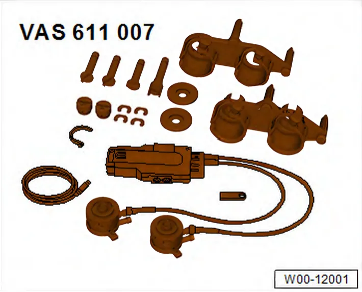
- Tester for checking elongation of chain links - VAS 611 007-
Procedure
- Remove resonator for intake air ⇒ 3.3 Removing and installing resonator for intake air.
- Remove air pipe ⇒ 2.5 Removing and installing air intake pipe.
- Remove connection for turbocharger ⇒ 1.4 Removing and installing connection for turbocharger.
- Set piston for cylinder no. 1 to TDC position ⇒ 4.7 Setting piston to TDC position.
- Drain coolant ⇒ 1.3 Draining and adding coolant.

- Unscrew bolts -2-.
- Remove cover for thermostat housing -1-.
- Unclip wiring harness -3- and place to one side.
- Unscrew bolts -1-.
- Place a cloth underneath to catch any oil which may drain out.
- Take off cap -5-.
- Pull off pipe -2-.
- Remove toothed belt cover -4-.
- Preassemble test tool - VAS 611 007- ⇒ 2.4.1 Preassembling test tool VAS 611 007 without ACT.
- Install test tool - VAS 611 007- ⇒ 2.4.3 Mounting test tool VAS 611 007 without ACT.
- Make sure that brakes -a- are released on both sides.

- Make sure that brake indicator on display is green -A-.
- It must not be yellow or red.
- Unscrew locking pin - T10340- -A-.
- Turn crankshaft 2 turns in direction of rotation of engine.
- Screw in locking pin - T10340- -A-.
- Set piston for cylinder no. 1 to TDC position ⇒ 4.7 Setting piston to TDC position.
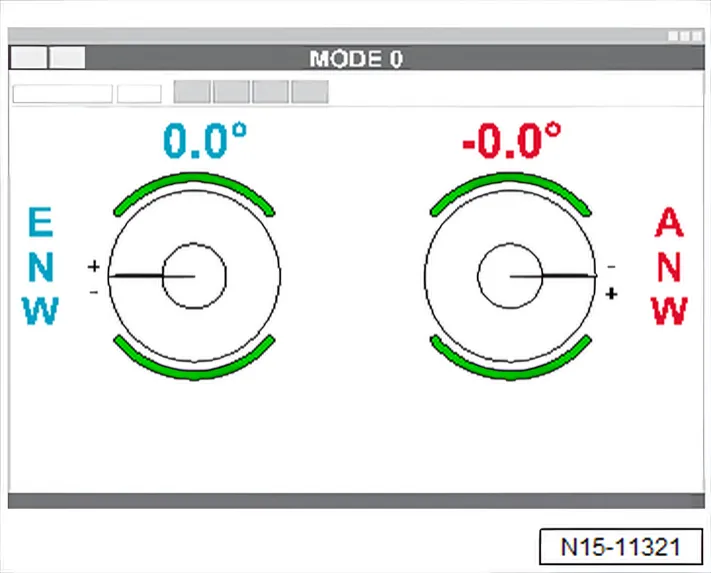
- Read valve timing angles on display, and compare values with specifications.
Specified values
| Inlet camshaft | Exhaust camshaft |
| -0.5° ±1.5° | +1.5° ±1.5° |
- If necessary, adjust timing. ⇒ 2.6 Adjusting valve timing
Assembly is carried out in reverse sequence; note the following:
- Add coolant ⇒ 1.3 Draining and adding coolant.
Polo 2010 LHD vehicles, Polo 2014 LHD vehicles, Polo Lim RUS 2016:
- Bleed brake system ⇒ Brake system; Rep. gr. 47; Hydraulic system.
Torque settings
- ⇒ 2.1 Assembly overview - coolant pump, thermostat
- ⇒ 3.1 Assembly overview - air filter housing
- ⇒ Brake system; Rep. gr. 45; Control unit and hydraulic unit; Assembly overview - control unit and hydraulic unit
- ⇒ Brake system; Rep. gr. 47; Brake servo/brake master cylinder, Assembly overview - brake servo/brake master cylinder
| Component | Torque setting |
| Bolt for TDC hole in cylinder block | 30 Nm |
2.5.2 Checking valve timing, vehicles with ACT
Special tools and workshop equipment required
- Tester for checking elongation of chain links - VAS 611 007-
Procedure
- Remove resonator for intake air ⇒ 3.3 Removing and installing resonator for intake air.
- Remove air pipe ⇒ 2.5 Removing and installing air intake pipe.
- Remove connection for turbocharger ⇒ 1.4 Removing and installing connection for turbocharger.
- Set piston for cylinder no. 1 to TDC position ⇒ 4.7 Setting piston to TDC position.
- Drain coolant ⇒ 1.3 Draining and adding coolant.
- Unscrew bolts -2-.
- Remove cover for thermostat housing -1-.
- Unclip wiring harness -3- and place to one side.
- Unscrew bolts -1-.
- Place a cloth underneath to catch any oil which may drain out.
- Take off cap -5-.
- Pull off pipe -2-.
- Remove toothed belt cover -4-.
- Preassemble test tool - VAS 611 007- ⇒ 2.4.2 Preassembling test tool VAS 611 007 with ACT.
- Install test tool - VAS 611 007- ⇒ 2.4.4 Mounting test tool VAS 611 007 with ACT.
- Make sure that brakes -a- are released on both sides.
- Make sure that brake indicator on display is green -A-.
- It must not be yellow or red.
- Unscrew locking pin - T10340- -A-.
- Turn crankshaft 2 turns in direction of rotation of engine.
- Screw in locking pin - T10340- -A-.
- Set piston for cylinder no. 1 to TDC position ⇒ 4.7 Setting piston to TDC position.
- Read valve timing angles on display, and compare values with specifications.
Specified values
| Inlet camshaft | Exhaust camshaft |
| -1.3° ±1.5° | +0.8° ±1.5° |
- If necessary, adjust timing. ⇒ 2.6 Adjusting valve timing
Assembly is carried out in reverse sequence; note the following:
- Add coolant ⇒ 1.3 Draining and adding coolant.
Polo 2010 LHD vehicles, Polo 2014 LHD vehicles, Polo Lim RUS 2016:
- Bleed brake system ⇒ Brake system; Rep. gr. 47; Hydraulic system.
Torque settings
- ⇒ 2.1 Assembly overview - coolant pump, thermostat
- ⇒ 3.1 Assembly overview - air filter housing
- ⇒ Brake system; Rep. gr. 45; Control unit and hydraulic unit; Assembly overview - control unit and hydraulic unit
- ⇒ Brake system; Rep. gr. 47; Brake servo/brake master cylinder, Assembly overview - brake servo/brake master cylinder
| Component | Torque setting |
| Bolt for TDC hole in cylinder block | 30 Nm |