
1.4 TSI engine (EA211) · Cylinder head, valve gear · Valve gear
Removing and installing valve stem seals
⇒ 3.7.1 Removing and installing valve stem seals (cylinder head installed)
⇒ 3.7.2 Removing and installing valve stem seals (cylinder head removed)
3.7.1 Removing and installing valve stem seals (cylinder head installed)
Special tools and workshop equipment required

- Spark plug socket - 3122 B-
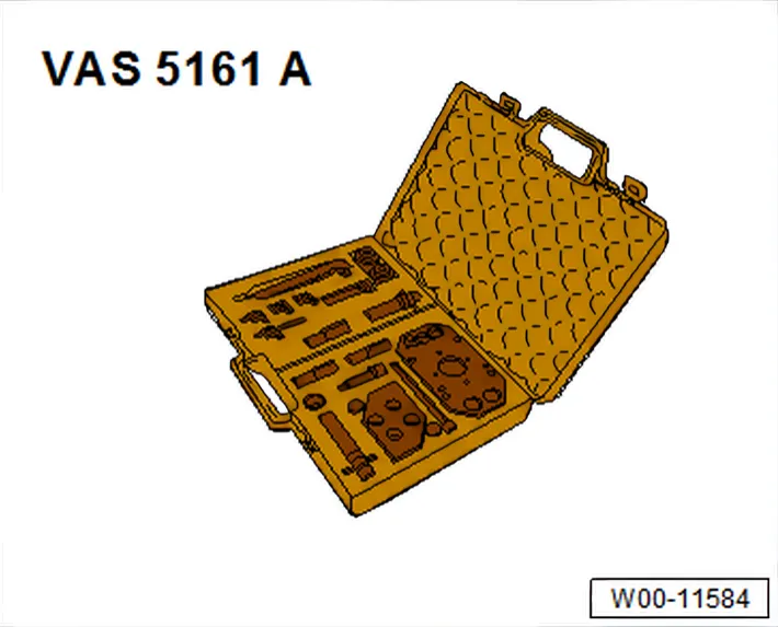
- Removal and installation device for valve cotters - VAS 5161A- with guide plate - VAS 5161A/32-32-.
- Hose adapter - VAS 5161A/35- (not shown)

- Valve stem seal fitting tool - 3365-
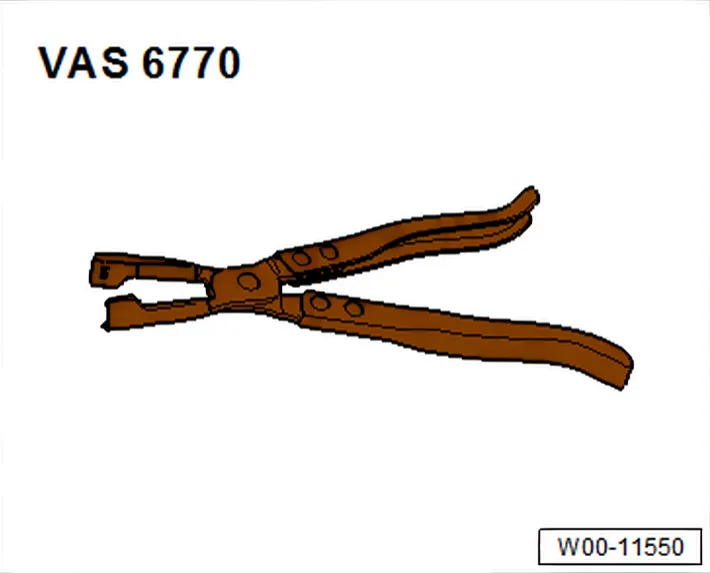
- Valve stem pliers - VAS 6770-
Procedure
- Remove camshaft housing ⇒ 1.4 Removing and installing camshaft housing.

- Mark allocation of roller rocker fingers -1-, hydraulic compensation element -4- and valves -3- for reinstallation.
- Remove roller rocker fingers together with compensation elements and place them on a clean surface.
- Unscrew spark plugs with spark plug socket - 3122 B-.
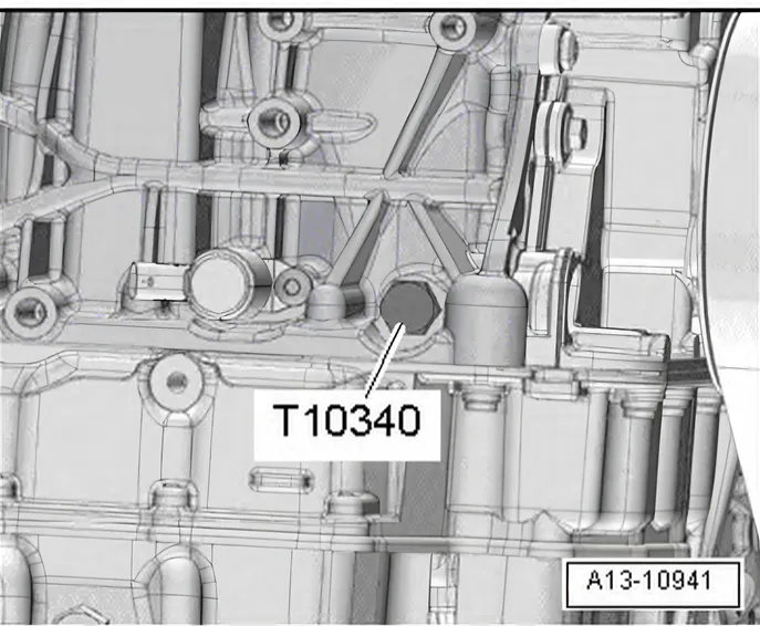
- Unscrew locking pin - T10340-.
- Set piston of respective cylinder to “bottom dead centre”.
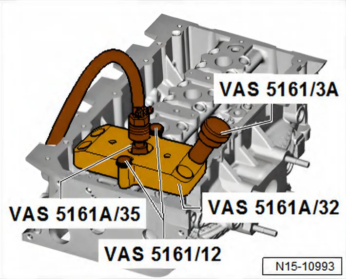
- Fit guide plate -VAS 5161A/32- onto cylinder head and secure with knurled screws -VAS 5161/12-.
- Screw hose adapter - VAS 5161A/35- into respective spark plug thread hand-tight.
- Connect adapter to compressed air supply using a commercially available union and apply pressure continuously.
- Minimum pressure: 6 bar.
- Insert punch -VAS 5161/3A- into guide plate.
- Use a plastic hammer to knock loose the firmly seated valve cotters.

- Screw toothed piece -VAS 5161/6- with hooking fork - VAS 5161/5- into guide plate.
- Slide sleeve -VAS 5161A/32-2- onto assembly cartridge and insert cartridge into guide plate -VAS 5161A/32-3-.
- Attach pressure fork -VAS 5161/2- to toothed piece and press assembly cartridge down.
- At the same time, turn knurled screw of assembly cartridge clockwise until tips engage in valve cotters.
- Move knurled screw back and forth to press apart valve cotters and capture them in assembly cartridge.
- Release pressure fork.
- Remove installation cartridge.
- Unbolt guide plate and move to side.
- The compressed air hose remains connected.
- Remove valve spring and valve spring plate.
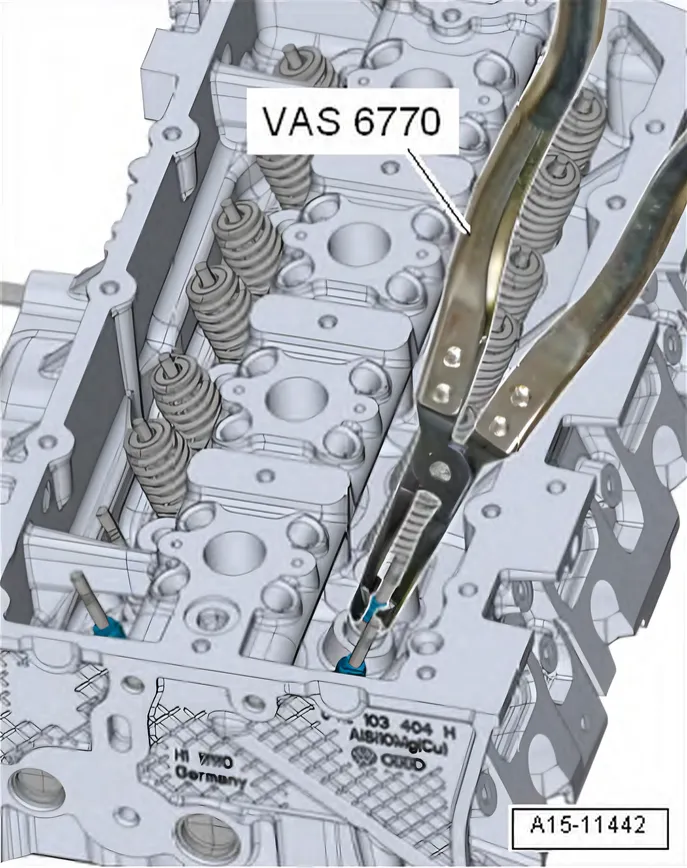
- Pull off valve stem seal using valve stem pliers - VAS 6770-.
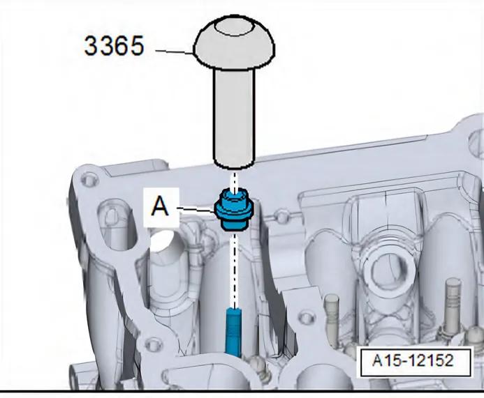
- Lightly oil sealing lip of valve stem seal -A-.
- Carefully press valve stem oil seal -A- onto valve guide using valve stem seal fitting tool - 3365-.
- Insert valve spring and valve spring plate. For installation position of valve spring refer to ⇒ 3.1 Assembly overview - valve gear.

If valve cotters have been removed from assembly cartridge:
- First, insert valve cotters into insertion device - VAS 5161 A/32-3-.
- Press down spring washer until 3 grooves are visible.
- Fit valve cotters into grooves.
- Larger diameter of valve cotters faces upwards.
- Release the spring washer. The spring force pushes the washer back upwards and holds the valve cotters in place.
- Press assembly cartridge - VAS 5161A/32-1- onto insertion device from above, and pick up valve cotters.
- To do this, move knurled screw back and forth to press apart valve cotters and capture them in assembly cartridge.
- Bolt guide plate -VAS 5161A/32-1- onto cylinder head again.
- Insert assembly cartridge -VAS 5161A/32-1- with sleeve -VAS 5161A/32-2- into guide plate.
- Press pressure fork downwards and pull knurled screw upwards, turning it clockwise and anticlockwise. This inserts the valve cotters.
- Reduce pressure on pressure fork whilst pulling on knurled screw.
- Repeat procedure on each valve.
Installing
Assemble in reverse order of dismantling. The following should be observed:
- Install spark plugs ⇒ Maintenance; Booklet.
- Install camshaft housing ⇒ 1.4 Removing and installing camshaft housing.
Torque settings
- ⇒ Running gear, axles, steering; Rep. gr. 40; Drive shaft; Assembly overview - drive shaft
- ⇒ 1.1 Assembly overview - turbocharger
- ⇒ 1.2 Assembly overview - camshaft housing
3.7.2 Removing and installing valve stem seals (cylinder head removed)
Special tools and workshop equipment required
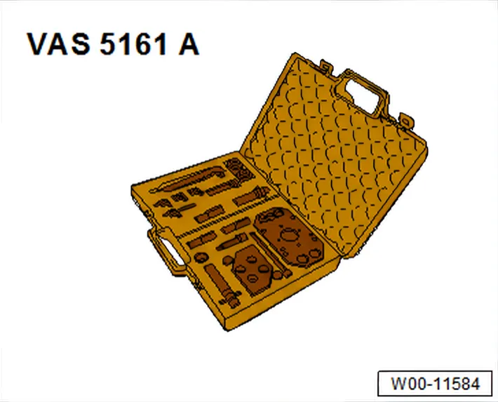
- Removal and installation device for valve cotters - VAS 5161A- with guide plate - VAS 5161A/32-32-.
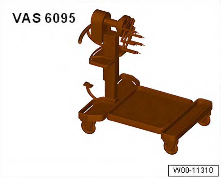
- Engine and gearbox support - VAS 6095-
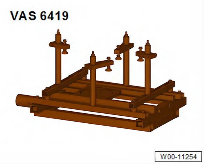
- Cylinder head tensioning device - VAS 6419-

- Valve stem pliers - VAS 6770-
- Valve stem seal fitting tool - 3365-
Procedure
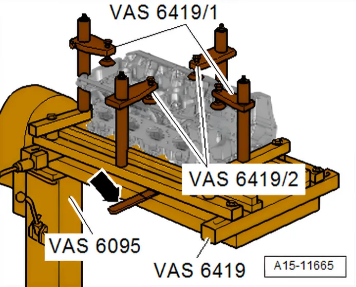
- Remove cylinder head ⇒ 1.3 Removing and installing cylinder head.
- Insert cylinder head tensioning device - VAS 6419- into engine and gearbox support - VAS 6095-.
- Tension cylinder head on cylinder head tensioning device as shown in illustration.
- Connect cylinder head tensioning device to compressed air.
- Use lever -arrow- to slide air cushion under combustion chamber from which valve stem seals are to be removed.
- Allow compressed air to flow into air cushion until it lies against valve disc.
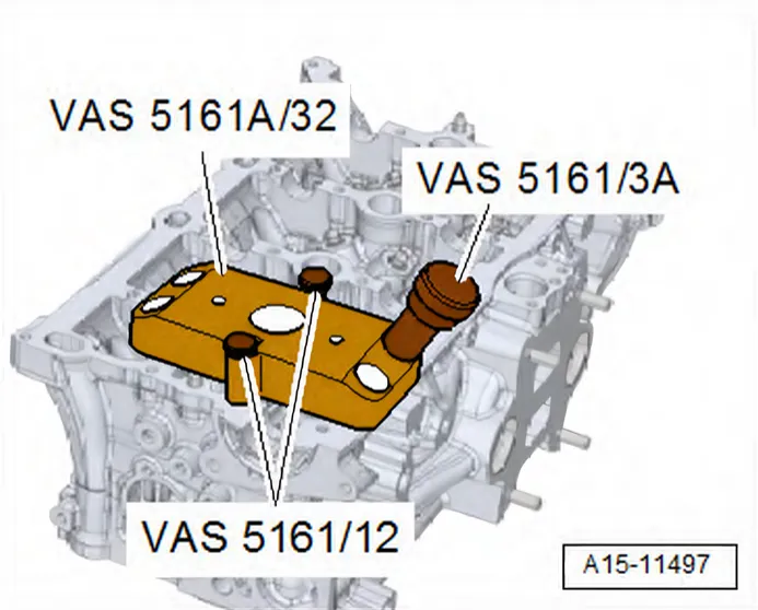
- Fit guide plate -VAS 5161A/32- onto cylinder head and secure with knurled screws -VAS 5161/12-.
- Insert punch -VAS 5161/3A- into guide plate.
- Use a plastic hammer to knock loose the firmly seated valve cotters.
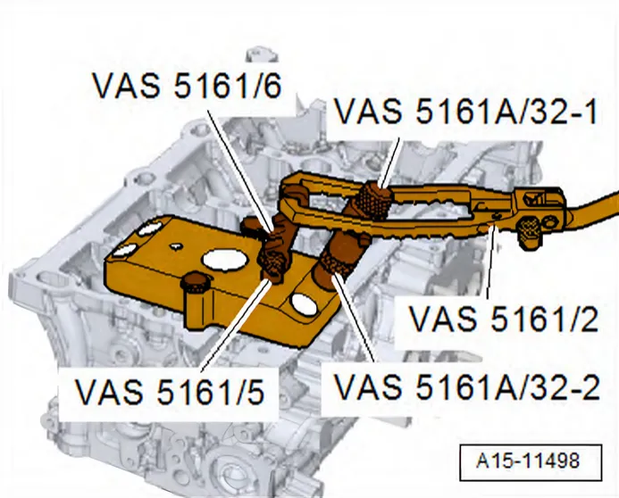
- Screw toothed piece -VAS 5161/6- with hooking fork - VAS 5161/5- into guide plate.
- Slide sleeve -VAS 5161A/32-1- onto assembly cartridge and insert cartridge into guide plate -VAS 5161A/32-2-.
- Attach pressure fork -VAS 5161/2- to toothed piece and press assembly cartridge down.
- At the same time, turn knurled screw of assembly cartridge clockwise until tips engage in valve cotters.
- Move knurled screw back and forth to press apart valve cotters and capture them in assembly cartridge.
- Release pressure fork.
- Remove installation cartridge.
- Unbolt guide plate and move to side.
- Remove valve spring and valve spring plate.
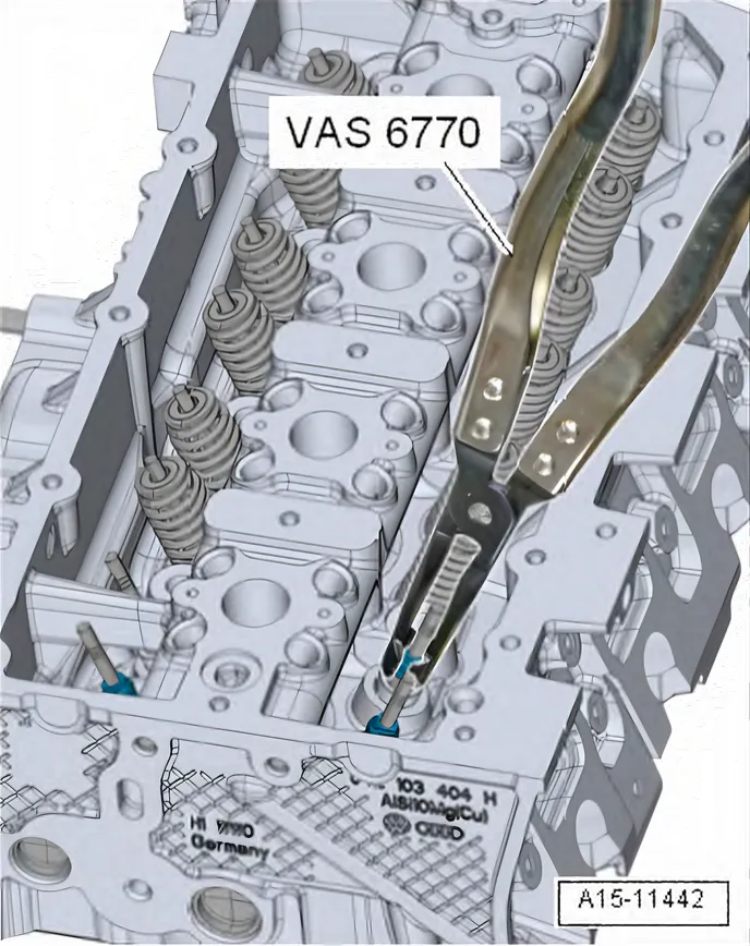
- Pull off valve stem seal using valve stem pliers - VAS 6770-.

- Lightly oil sealing lip of valve stem seal -A-.
- Carefully press valve stem oil seal -A- onto valve guide using valve stem seal fitting tool - 3365-.
- Insert valve spring and valve spring plate. For installation position of valve spring refer to ⇒ 3.1 Assembly overview - valve gear.

If valve cotters have been removed from assembly cartridge:
- First, insert valve cotters into insertion device - VAS 5161 A/32-3-.
- Press down spring washer until 3 grooves are visible.
- Fit valve cotters into grooves.
- Larger diameter of valve cotters faces upwards.
- Release the spring washer. The spring force pushes the washer back upwards and holds the valve cotters in place.
- Press assembly cartridge - VAS 5161A/32-1- onto insertion device from above, and pick up valve cotters.
- To do this, move knurled screw back and forth to press apart valve cotters and capture them in assembly cartridge.
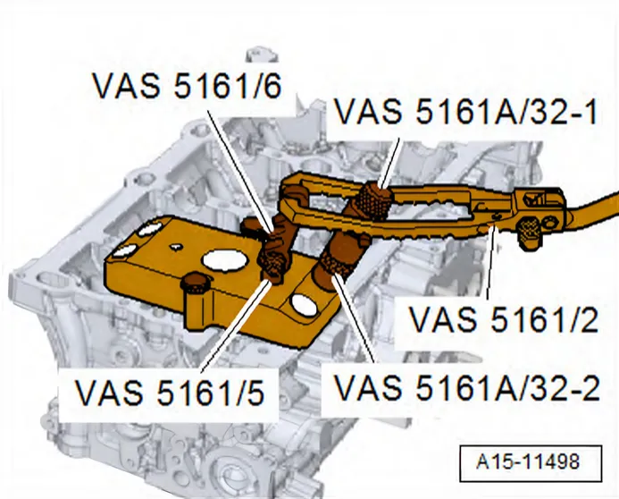
- Bolt guide plate -VAS 5161A/32- onto cylinder head again.
- Insert assembly cartridge -VAS 5161A/32-1- with sleeve -VAS 5161A/32-2- into guide plate.
- Press pressure fork downwards and pull knurled screw upwards, turning it clockwise and anticlockwise. This inserts the valve cotters.
- Reduce pressure on pressure fork whilst pulling on knurled screw.
- Repeat procedure on each valve.
- Install cylinder head ⇒ 1.3 Removing and installing cylinder head.