
1.4 TSI engine (EA211) · Cylinder head, valve gear · Toothed belt drive
Adjusting valve timing
⇒ 2.6.1 Adjusting valve timing, vehicles without ACT
⇒ 2.6.2 Adjusting valve timing, vehicles with Active Cylinder Management
2.6.1 Adjusting valve timing, vehicles without ACT
Special tools and workshop equipment required

- Locating bolt - T10340-

- Engine bung set - VAS 6122-
Procedure
- Toothed belt installed.
- Check valve timing ⇒ 2.5 Checking valve timing.
- Set piston for cylinder no. 1 to TDC position ⇒ 4.7 Setting piston to TDC position.
- Do not relieve tension from toothed belt, and do not remove toothed belt from camshafts when adjusting valve timing. Only loosen camshaft adjuster or toothed belt sprocket.
- Loosen camshaft adjuster on inlet side ⇒ 3.3.2 Removing and installing inlet side camshaft adjuster, exhaust side with toothed belt sprocket.
Exhaust side with toothed belt sprocket
- Loosen toothed belt sprocket on exhaust side ⇒ 3.4 Removing and installing toothed belt pulley.
Exhaust side with camshaft adjuster
- Loosen camshaft adjuster on exhaust side ⇒ 3.3.3 Removing and installing camshaft adjuster for exhaust camshaft.
Continuation for all vehicles
| NOTICE |
Risk of damage to engine caused by incorrect valve timing.
- Do not turn crankshaft out of TDC position.
- Place a cloth under the camshaft adjusters and over tensioning roller to catch the engine oil which runs out.
- The contact points between the toothed belt and components
- such as camshaft pulleys, tensioning roller and idler pulley - must be kept free of oil.
- Catch any engine oil which runs out immediately, and remove it.
- Remove engine oil at camshaft adjusters.
- Make sure that the piston in cylinder no. 1 is at TDC position ⇒ 4.7 Setting piston to TDC position.
Exhaust side with toothed belt sprocket
- Renew bolt -2- and screw in loosely.
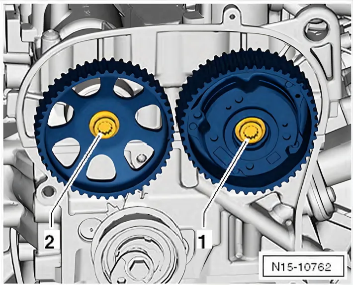
- Renew bolt -1- and screw in loosely.
Exhaust side with camshaft adjuster
- Renew bolt -2- and screw in loosely.

- Renew bolt -1- and screw in loosely.
Continued for all vehicles
- It should still be possible to turn the camshaft adjuster and toothed belt sprocket on the camshafts.
Setting camshafts to »0°«:
- Make sure that bolts -a- for brakes are released on both sides.
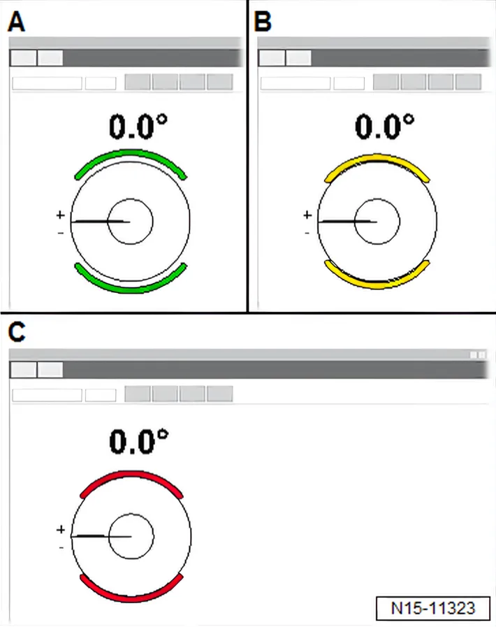
- Make sure that the brake indicator on the display is »green«
- A-.
- Display must not be »yellow« or »red«.
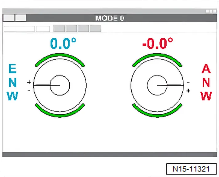
- Set both camshafts to »0.0°«.
- To do this, turn camshafts with adapter for angle sensor - VAS 611 007/5- -E-.
- Hold camshafts via adapter for angle sensor - VAS 611 007/9- and adapter for angle sensor - VAS 611 007/10- -E- in »0.0°« position with a wrench.
- Tighten brakes after adjustment has been completed.
- Tighten bolts -a- for brakes to 11 Nm on both sides.
- Make sure that the brake indicator on the display is »red«
- C-.
- Display must not be »yellow« or »green«.
- Unscrew locking pin - T10340- -A-.
- Tighten camshaft adjuster on inlet camshaft to specified initial torque ⇒ Fig. ““”“, page 166.
Continued for all vehicles
- Make sure that bolts -a- for brakes are released on both sides.
- Make sure that the brake indicator on the display is »green«
- A-.
- Display must not be »yellow« or »red«.
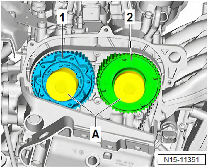
- Seal camshaft adjuster -2- using suitable plugs -A- from engine bung set - VAS 6122-.
- Fit a piece of paper -A- into plugs to catch the engine oil.
- Insert plugs into camshaft adjusters with the open side facing towards front, as shown in illustration.
- Turn crankshaft 2 turns in direction of rotation of engine.
Determining correction angle
- Screw in locking pin - T10340-.
- Set piston for cylinder no. 1 to TDC position ⇒ 4.7 Setting piston to TDC position.
- Read valve timing on display and write down values.
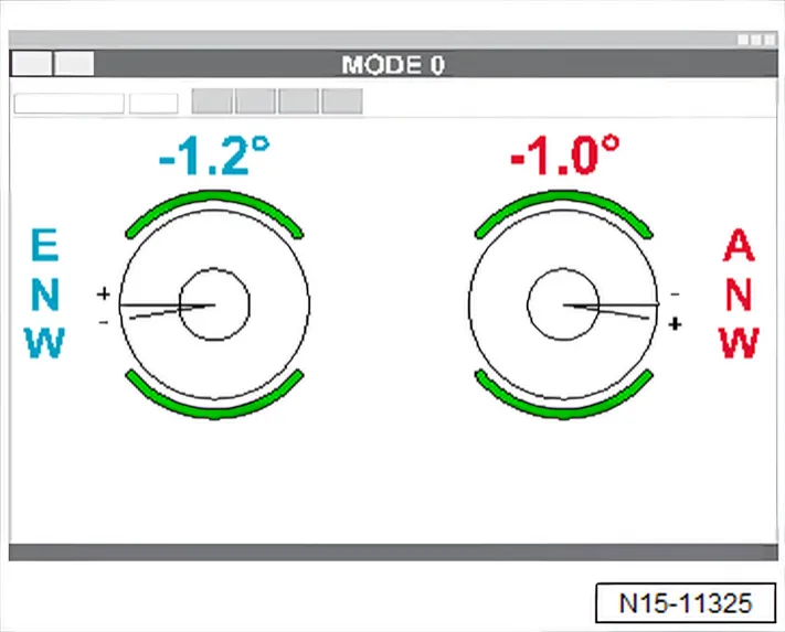
- Measurement example: value reading on display
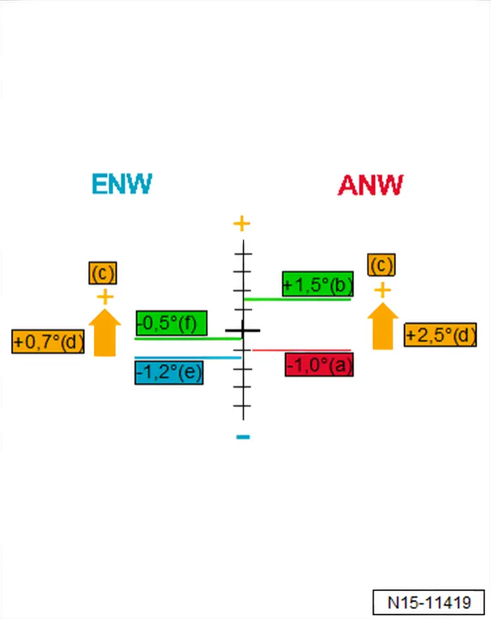
Example
| Index | Explanation |
|---|---|
| e | Inlet camshaft - actual value (after 2 full revolutions of the engine) |
| f | Inlet camshaft - specification (+/- tolerance) |
| c | Direction of correction (+/-) |
| d | Correction value - correction angle |
| a | Exhaust camshaft - actual value (after 2 full revolutions of the engine) |
| b | Exhaust camshaft - specification (+/- tolerance) |
| Angle in ° | Inlet camshaft | Exhaust camshaft |
| Specified angle | -0.5°±1.5° | +1.5°±1.5° |
- Set determined correction angle for camshafts.
Setting valve timing with correction angle
- Place a cloth underneath camshaft adjuster to catch any engine oil which runs out.
- Remove plug taken from engine bung set - VAS 6122- from camshaft adjuster.
- Remove paper from plugs and camshaft adjusters.
- Clean camshaft adjusters with a cleaning cloth and remove as much engine oil as possible.
- Loosen camshaft adjuster on inlet side ⇒ 3.3.2 Removing and installing inlet side camshaft adjuster, exhaust side with toothed belt sprocket.
Exhaust side with toothed belt sprocket
- Loosen toothed belt sprocket on exhaust side ⇒ 3.4 Removing and installing toothed belt pulley.
Exhaust side with camshaft adjuster
- Loosen camshaft adjuster on exhaust side ⇒ 3.3.3 Removing and installing camshaft adjuster for exhaust camshaft.
Continuation for all vehicles
| NOTICE |
Risk of damage to engine caused by incorrect valve timing.
- Do not turn crankshaft out of TDC position.
- Make sure that the piston in cylinder no. 1 is at TDC position ⇒ 4.7 Setting piston to TDC position.
- Make sure that bolts -a- for brakes on test tool - VAS 611 007- are released on both sides.
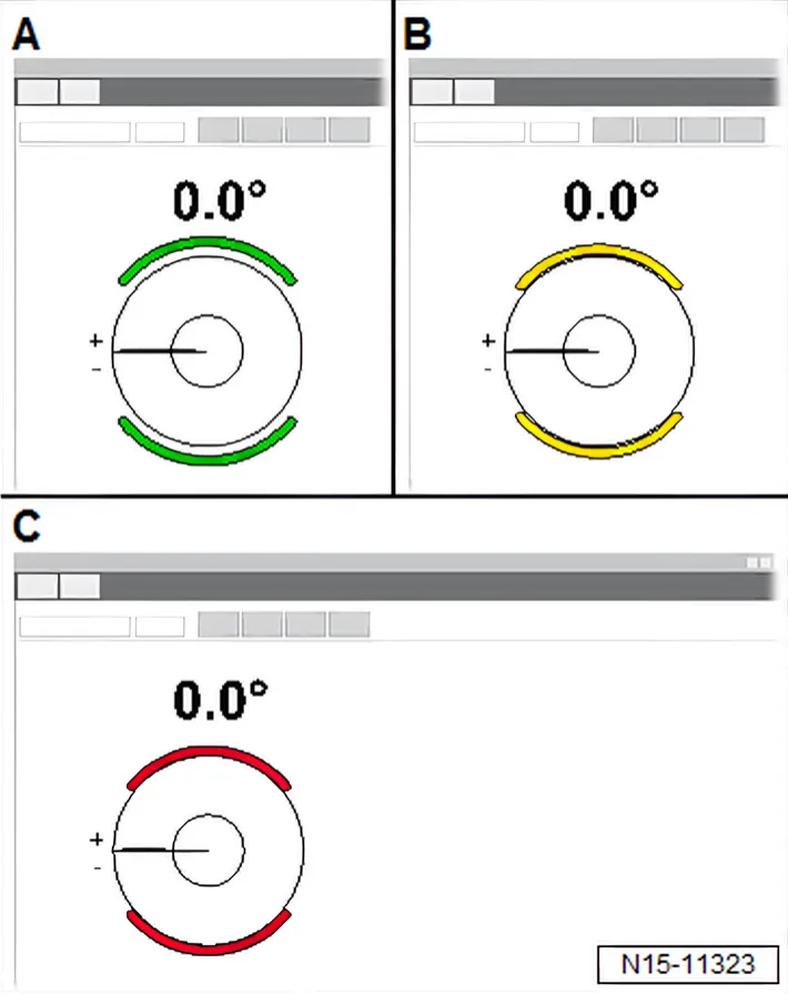
- Make sure that the brake indicator on the display is »green«
- A-.
- Display must not be »yellow« or »red«.
- Set the two camshafts to the determined correction angle ⇒ 2.6.1 Adjusting valve timing, vehicles without ACT.
- To do this, turn camshafts with adapter for angle sensor - VAS 611 007/9- and adapter for angle sensor - VAS 611 007/10-
- E-.
If the valve timing has been set:
- Tighten bolts -a- for brakes on test tool - VAS 611 007- to 11 Nm on both sides.
- Make sure that brake indicator on display is red -C-.
- Display must not be »yellow« or »green«.
- Unscrew locking pin - T10340- -A-.
- Tighten camshaft adjuster on inlet camshaft to specified initial torque ⇒ Fig. ““”“, page 166.
Exhaust side with toothed belt sprocket
- Tighten toothed belt sprocket of exhaust camshaft to specified initial torque ⇒ 3.4 Removing and installing toothed belt pulley.
Exhaust side with camshaft adjuster
- Tighten camshaft adjuster of exhaust camshaft to specified initial torque ⇒ 3.4 Removing and installing toothed belt pulley.
Continued for all vehicles
- Release brakes -a- on both sides.
- Make sure that the brake indicator on the display is »green«
- A-.
- Display must not be »yellow« or »red«.
- Seal camshaft adjusters -1- and -2- using suitable plugs -A- from engine bung set - VAS 6122-.
- Fit a new piece of paper into plugs -A- to catch the engine oil.
- The plug for the camshaft adjuster -1- on exhaust side must be pushed in slightly.
- Turn crankshaft 2 turns in direction of rotation of engine.
- Screw in locking pin - T10340-.
- Set piston for cylinder no. 1 to TDC position ⇒ 4.7 Setting piston to TDC position.
- Read valve timing, and compare it with specifications.
Specified angle in °
| Inlet camshaft | Exhaust camshaft |
| -0.5° ±1.5° | +1.5° ±1.5° |
- If the valve timing is not OK, adjust valve timing again.
Assembly is carried out in reverse sequence; note the following:
- Unscrew locking pin - T10340-.
- Make sure that brakes on test tool - VAS 611 007- are released on both sides.
- Tighten camshaft adjuster on inlet camshaft to specified final torque ⇒ Fig. ““”“, page 166.
Exhaust side with toothed belt sprocket
- Tighten toothed belt sprocket of exhaust camshaft to specified final torque ⇒ 3.4 Removing and installing toothed belt pulley.
Exhaust side with camshaft adjuster
- Tighten camshaft adjuster of exhaust camshaft to specified final torque ⇒ 3.3.1 Removing and installing inlet side camshaft adjuster, exhaust side with camshaft adjuster.
Torque settings
- ⇒ 2.2 Assembly overview - toothed belt
- ⇒ 2.1 Assembly overview - coolant pump, thermostat
- ⇒ 3.1 Assembly overview - air filter housing
2.6.2 Adjusting valve timing, vehicles with Active Cylinder Management
Special tools and workshop equipment required
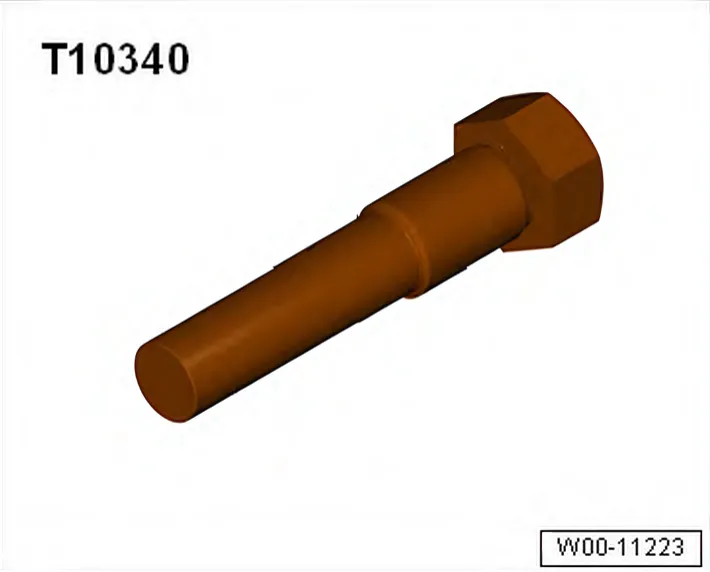
- Locating bolt - T10340-
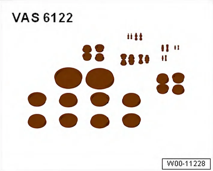
- Engine bung set - VAS 6122-
Procedure
- Toothed belt installed.
- Check valve timing ⇒ 2.5 Checking valve timing.
- Set piston for cylinder no. 1 to TDC position ⇒ 4.7 Setting piston to TDC position.
- Do not relieve tension from toothed belt, and do not remove toothed belt from camshafts when adjusting valve timing. Only loosen camshaft adjuster or toothed belt sprocket.
- Loosen camshaft adjuster on inlet side ⇒ 3.3.2 Removing and installing inlet side camshaft adjuster, exhaust side with toothed belt sprocket.
Exhaust side with toothed belt sprocket
- Loosen toothed belt sprocket on exhaust side ⇒ 3.4 Removing and installing toothed belt pulley.
Exhaust side with camshaft adjuster
- Loosen camshaft adjuster on exhaust side ⇒ 3.3.3 Removing and installing camshaft adjuster for exhaust camshaft.
Continuation for all vehicles
| NOTICE |
Risk of damage to engine caused by incorrect valve timing.
- Do not turn crankshaft out of TDC position.
- Place a cloth under the camshaft adjusters and over tensioning roller to catch the engine oil which runs out.
- The contact points between the toothed belt and components
- such as camshaft pulleys, tensioning roller and idler pulley - must be kept free of oil.
- Catch any engine oil which runs out immediately, and remove it.
- Remove engine oil at camshaft adjusters.
- Make sure that the piston in cylinder no. 1 is at TDC position ⇒ 4.7 Setting piston to TDC position.
Exhaust side with toothed belt sprocket
- Renew bolt -2- and screw in loosely.
- Renew bolt -1- and screw in loosely.
Exhaust side with camshaft adjuster
- Renew bolt -2- and screw in loosely.
- Renew bolt -1- and screw in loosely.
Continued for all vehicles
- It should still be possible to turn the camshaft adjuster and toothed belt sprocket on the camshafts.
Setting camshafts to »0°«:
- Make sure that bolts -a- for brakes are released on both sides.
- Make sure that the brake indicator on the display is »green«
- A-.
- Display must not be »yellow« or »red«.
- Set both camshafts to »0.0°«.
- To do this, turn camshafts with adapter for angle sensor - VAS 611 007/5- -E-.
- Hold camshafts via adapter for angle sensor - VAS 611 007/9- and adapter for angle sensor - VAS 611 007/10- -E- in »0.0°« position with a wrench.
- Tighten brakes after adjustment has been completed.
- Tighten bolts -a- for brakes to 11 Nm on both sides.
- Make sure that the brake indicator on the display is »red«
- C-.
- Display must not be »yellow« or »green«.
- Unscrew locking pin - T10340- -A-.
- Tighten camshaft adjuster on inlet camshaft to specified initial torque ⇒ Fig. ““”“, page 166.
Continued for all vehicles
- Make sure that bolts -a- for brakes are released on both sides.
- Make sure that the brake indicator on the display is »green«
- A-.
- Display must not be »yellow« or »red«.
- Seal camshaft adjuster -2- using suitable plugs -A- from engine bung set - VAS 6122-.
- Fit a piece of paper -A- into plugs to catch the engine oil.
- Insert plugs into camshaft adjusters with the open side facing towards front, as shown in illustration.
- Turn crankshaft 2 turns in direction of rotation of engine.
Determining correction angle
- Screw in locking pin - T10340-.
- Set piston for cylinder no. 1 to TDC position ⇒ 4.7 Setting piston to TDC position.
- Read valve timing on display and write down values.
- Measurement example: value reading on display
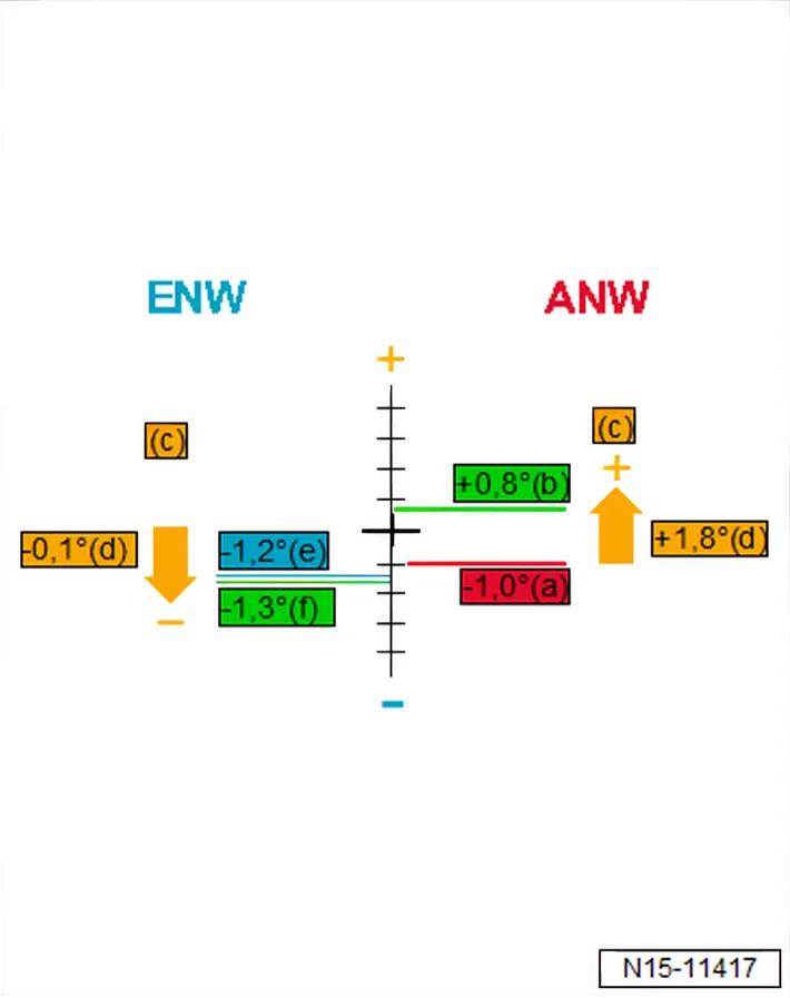
Calculation example ACT
Example
| Index | Explanation |
|---|---|
| e | Inlet camshaft - actual value (after 2 full revolutions of the engine) |
| f | Inlet camshaft - specification (+/- tolerance) |
| c | Direction of correction (+/-) |
| d | Correction value - correction angle |
| a | Exhaust camshaft - actual value (after 2 full revolutions of the engine) |
| b | Exhaust camshaft - specification (+/- tolerance) |
| Angle in ° | Inlet camshaft | Exhaust camshaft |
| Specified angle | -1.3°±1.5° | +0.8°±1.5° |
- Set determined correction angle for camshafts.
Setting valve timing with correction angle
- Place a cloth underneath camshaft adjuster to catch any engine oil which runs out.
- Remove plug taken from engine bung set - VAS 6122- from camshaft adjuster.
- Remove paper from plugs and camshaft adjusters.
- Clean camshaft adjusters with a cleaning cloth and remove as much engine oil as possible.
- Loosen camshaft adjuster on inlet side ⇒ 3.3.2 Removing and installing inlet side camshaft adjuster, exhaust side with toothed belt sprocket.
Exhaust side with toothed belt sprocket
- Loosen toothed belt sprocket on exhaust side ⇒ 3.4 Removing and installing toothed belt pulley.
Exhaust side with camshaft adjuster
- Loosen camshaft adjuster on exhaust side ⇒ 3.3.3 Removing and installing camshaft adjuster for exhaust camshaft.
Continuation for all vehicles
| NOTICE |
Risk of damage to engine caused by incorrect valve timing.
- Do not turn crankshaft out of TDC position.
- Make sure that the piston in cylinder no. 1 is at TDC position ⇒ 4.7 Setting piston to TDC position.
- Make sure that bolts -a- for brakes on test tool - VAS 611 007- are released on both sides.
- Make sure that the brake indicator on the display is »green«
- A-.
- Display must not be »yellow« or »red«.
- Set the two camshafts to the determined correction angle ⇒ 2.6.1 Adjusting valve timing, vehicles without ACT.
- To do this, turn camshafts with adapter for angle sensor - VAS 611 007/9- and adapter for angle sensor - VAS 611 007/10-
- E-.
If the valve timing has been set:
- Tighten bolts -a- for brakes on test tool - VAS 611 007- to 11 Nm on both sides.
- Make sure that brake indicator on display is red -C-.
- Display must not be »yellow« or »green«.
- Unscrew locking pin - T10340- -A-.
- Tighten camshaft adjuster on inlet camshaft to specified initial torque ⇒ Fig. ““”“, page 166.
Exhaust side with toothed belt sprocket
- Tighten toothed belt sprocket of exhaust camshaft to specified initial torque ⇒ 3.4 Removing and installing toothed belt pulley.
Exhaust side with camshaft adjuster
- Tighten camshaft adjuster of exhaust camshaft to specified initial torque ⇒ 3.4 Removing and installing toothed belt pulley.
Continued for all vehicles
- Release brakes -a- on both sides.
- Make sure that the brake indicator on the display is »green«
- A-.
- Display must not be »yellow« or »red«.
- Seal camshaft adjusters -1- and -2- using suitable plugs -A- from engine bung set - VAS 6122-.
- Fit a new piece of paper into plugs -A- to catch the engine oil.
- The plug for the camshaft adjuster -1- on exhaust side must be pushed in slightly.
- Turn crankshaft 2 turns in direction of rotation of engine.
- Screw in locking pin - T10340-.
- Set piston for cylinder no. 1 to TDC position ⇒ 4.7 Setting piston to TDC position.
- Read valve timing, and compare it with specifications.
Specified angle in °
| Inlet camshaft | Exhaust camshaft |
| -1.3° ±1.5° | +0.8° ±1.5° |
- If the valve timing is not OK, adjust valve timing again.
Assembly is carried out in reverse sequence; note the following:
- Unscrew locking pin - T10340-.
- Make sure that brakes on test tool - VAS 611 007- are released on both sides.
- Tighten camshaft adjuster on inlet camshaft to specified final torque ⇒ Fig. ““”“, page 166.
Exhaust side with toothed belt sprocket
- Tighten toothed belt sprocket of exhaust camshaft to specified final torque ⇒ 3.4 Removing and installing toothed belt pulley.
Exhaust side with camshaft adjuster
- Tighten camshaft adjuster of exhaust camshaft to specified final torque ⇒ 3.3.1 Removing and installing inlet side camshaft adjuster, exhaust side with camshaft adjuster.
Torque settings