
1.4 TSI engine (EA211) · Crankshaft group · Cylinder block, gearbox end
Removing and installing sealing flange on gearbox side
Special tools and workshop equipment required
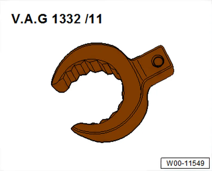
- Flared ring spanner tool insert AF 24 - V.A.G 1332/11-
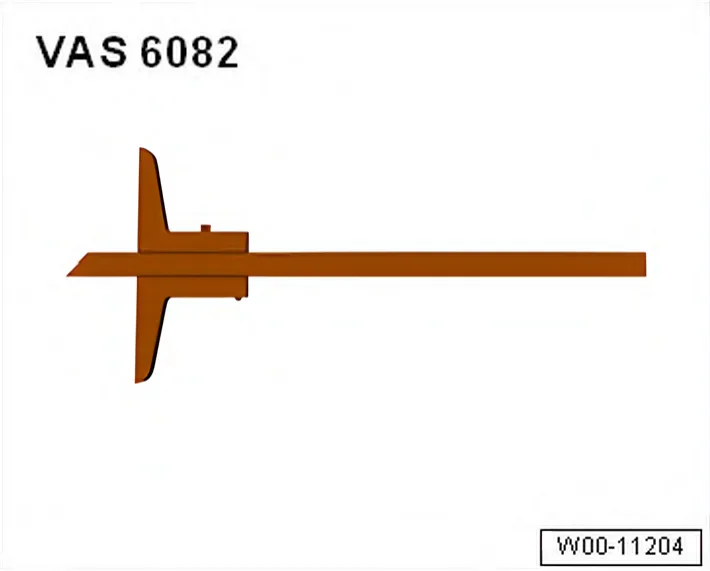
- Depth gauge - VAS 6082-
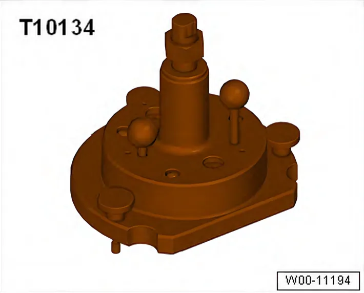
- Assembly tool - T10134-
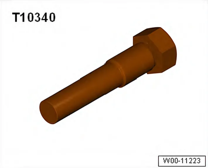
- Locating bolt - T10340-
- Bolt M6x35 (3x)
Procedure
- Gearbox is removed.
- Remove clutch ⇒ Rep. gr. 30; Removing and installing clutch.
- Remove flywheel ⇒ 2.2 Removing and installing flywheel.
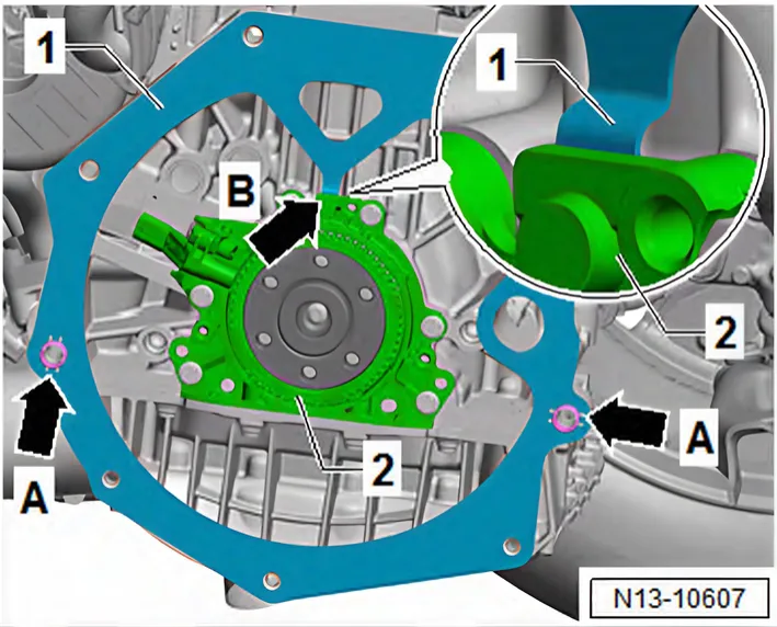
- Remove intermediate plate -1- from dowel sleeves -arrows A-.
- Guide intermediate plate -1- upwards.
- While doing so, pull retaining lug -arrow B- of intermediate plate -1- out of recess behind sealing flange.
- Set crankshaft to “TDC” position ⇒ 4.7 Setting piston to TDC position.
- Remove sump (bottom section) ⇒ 1.3 Removing and installing lower part of sump.
- Remove upper part of sump ⇒ 1.4 Removing and installing upper part of sump.
- Remove engine speed sender - G28- ⇒ 1.5 Removing and installing engine speed sender G28 .
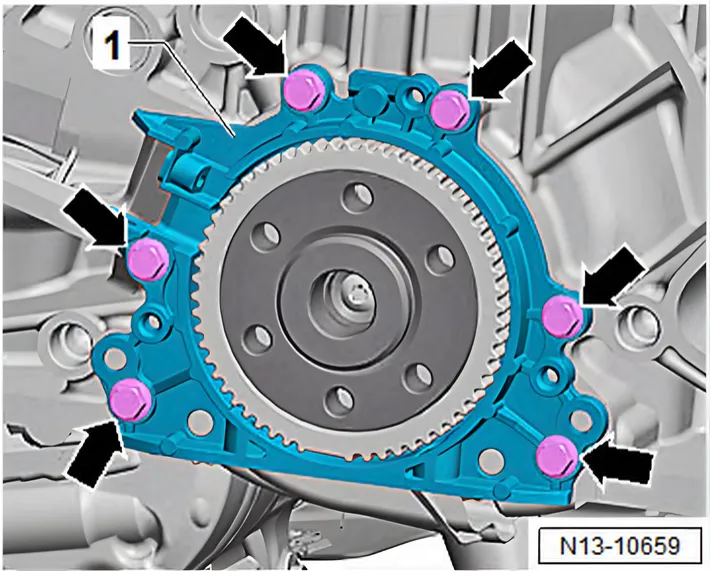
- Unscrew bolts -arrows- for sealing flange -1-.
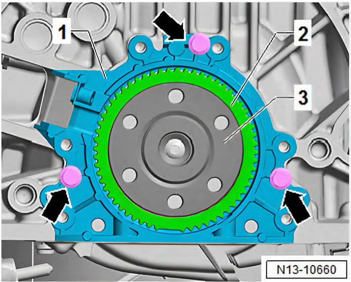
- To press off, screw 3 M6 x 35 bolts -arrows- into sealing flange -1-.
- Screw bolts alternately into sealing flange not more than 1/2 turn at a time.
- Remove sealing flange -1- together with sender wheel -2-.
Pressing in sealing flange with sender wheel
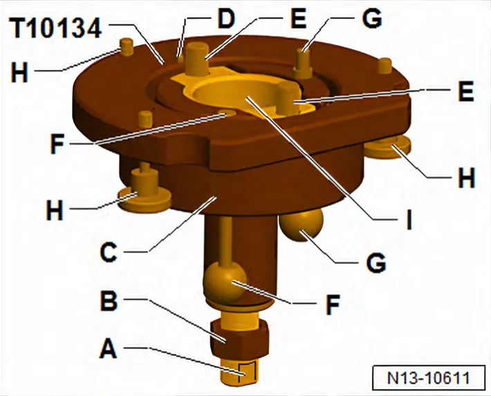
Set-up of assembly tool - T10134- :
A - Clamping surface
B - Nut
C - Assembly housing
D - Locating pin
E - Hexagon socket head bolt (qty. 2)
F - Guide pin for petrol engines (red knob)
G - Guide pin for diesel engines (black knob)
H - Knurled screws (qty. 3)
I - Inner part
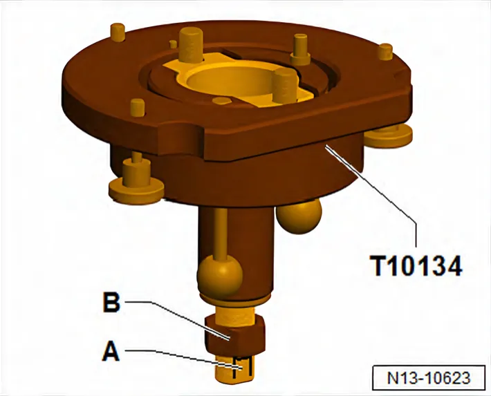
Fitting sealing flange with sender wheel on assembly tool - T10134- :
- Screw on nut -B- until just before it touches the clamping surface -A- of the threaded spindle.
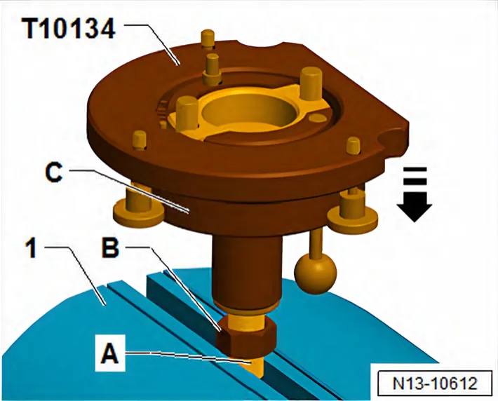
- Clamp assembly device - T10134- at clamping surface -A- of threaded spindle in a vice -1-.
- Press assembly housing -C- downwards until it rests against nut -B-.
- Inner part of assembly tool and assembly housing must be at same height.
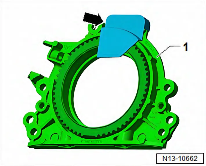
- If fitted, remove securing clip -arrow- from new sealing flange.
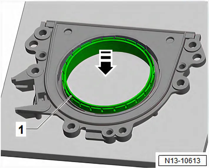
- Place sealing flange with front side facing down on a clean level surface.
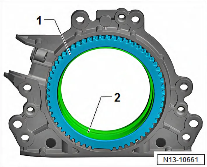
- Push sealing lip support ring -1- downwards in -direction of arrow- until it rests against the flat surface.
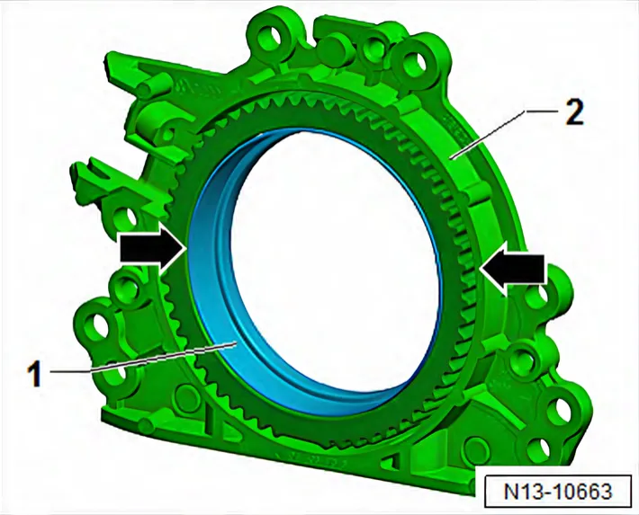
- Upper edge of sealing lip support ring -1- and front edge of sealing flange -2- must align -arrows-.
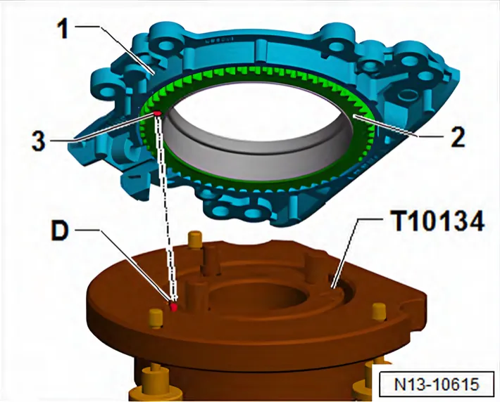
- Place sealing flange -1- with front side facing downwards onto assembly tool - T10134- so that locating pin -D- is seated in hole -3- in sender wheel hole -2-.
- If necessary, rotate sender wheel with support ring so that locating pin and hole align.
- The sealing flange must rest flat against the assembly tool.
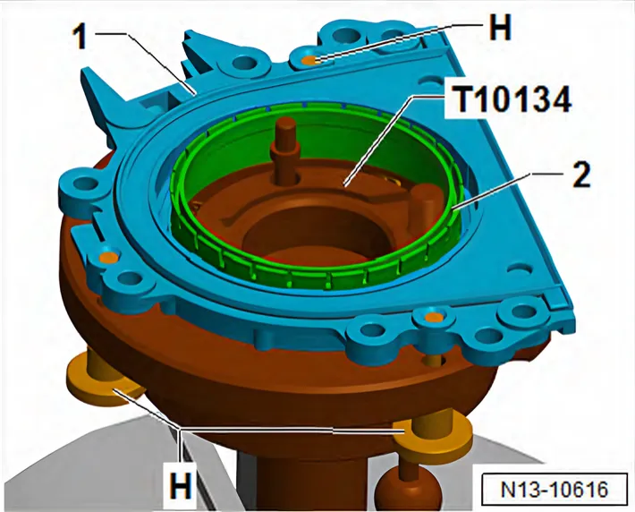
- Screw knurled screws -H- into sealing flange -1-.
- Press sealing flange -1- and sealing lip support ring -2- against surface of assembly tool - T10134- whilst tightening knurled screws.
- This prevents the locating pin from slipping out of the sender wheel hole.
- When installing sealing flange, ensure that sender wheel remains fixed in assembly tool.
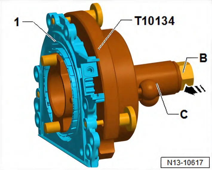
Mounting assembly tool - T10134- with sealing flange -1- on crankshaft flange:
- The crankshaft flange must be free of grease and oil.
- Engine is at “TDC” position.
- Screw on nut -B- until it reaches end of threaded spindle.
- Press threaded spindle of assembly tool - T10134- in -direction of arrow-, until nut -B- rests against assembly housing -C-.
- Align flat side of assembly housing to sealing surface of cylinder block on sump side.
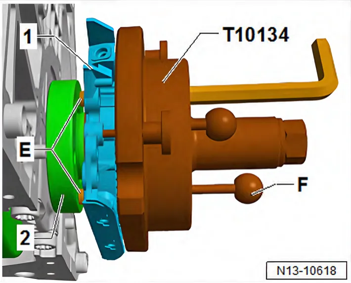
- Attach assembly tool - T10134- together with sealing flange -1- to crankshaft flange -2-.
- To do this, screw hexagon socket head bolts -E- into crankshaft flange (approx. 5 full turns) using a hexagon key.
- Push guide pin for petrol engines (red knob) -F- into crankshaft flange.
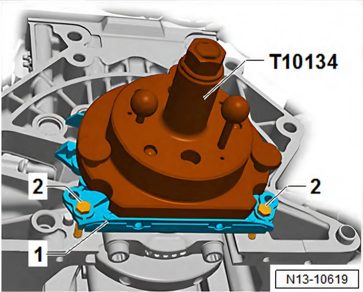
- To guide sealing flange -1-, screw two M6×35 mm bolts -2- into cylinder block.
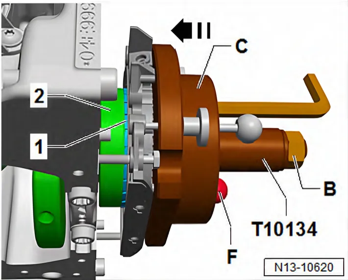
Bolting assembly tool - T10134- onto crankshaft flange:
- Push assembly housing -C- by hand in -direction of arrow- until sealing lip support ring -1- rests against crankshaft flange -2-.
- Make sure that guide pin for petrol engines (red knob) -F- is properly seated in hole in crankshaft. This ensures that the sender wheel reaches its final installation position.
- Tighten the two hexagon socket head bolts of assembly tool hand-tight.
- Screw nut -B- onto threaded spindle by hand until nut rests against assembly housing -C-.
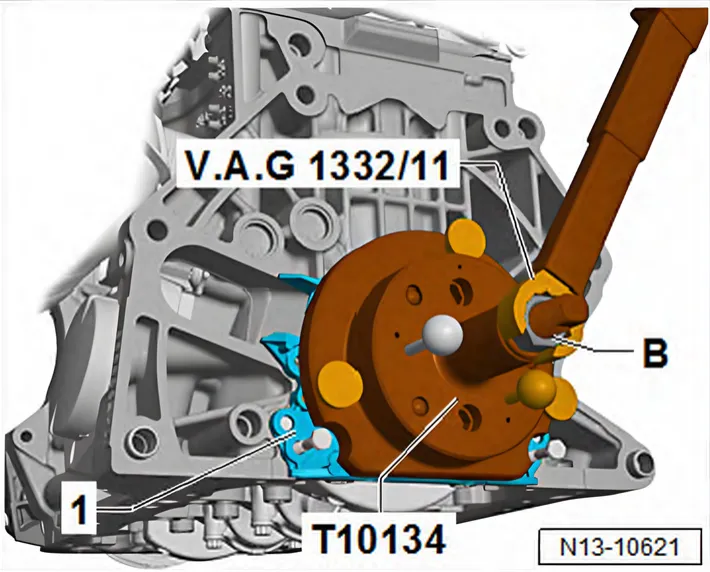
Pressing sender wheel onto crankshaft flange using assembly tool - T10134- :
- Tighten nut -B- of assembly tool - T10134- to 35 Nm.
- After the nut has been tightened to 35 Nm, a small air gap must still be present between cylinder block and sealing flange -1-.
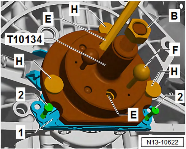
Checking sender wheel installation position on crankshaft:
- Screw on nut -B- until it reaches end of threaded spindle.
- Unscrew the two bolts -2- from cylinder block.
- Pull guide pin for petrol engines (red knob) -F- out of crankshaft flange.
- Unscrew knurled screws -H- from sealing flange -1-.
- Unbolt assembly tool - T10134- from crankshaft flange, unscrewing hexagon socket head bolts -E- from crankshaft flange.
- Remove sealing lip support ring.
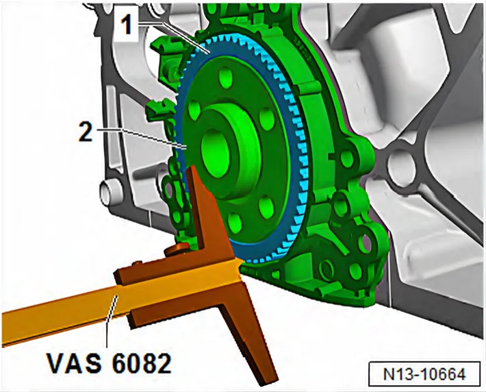
- Position depth gauge - VAS 6082- on crankshaft flange -2-.
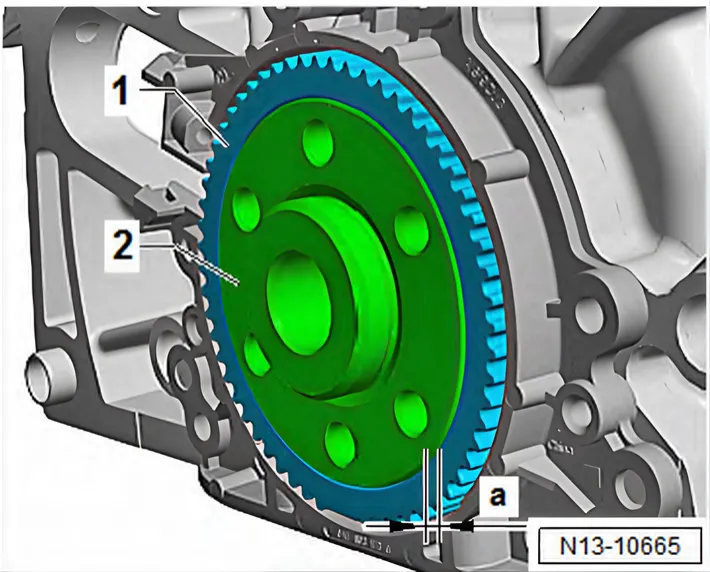
- Measure distance -a- between crankshaft flange -2- and sender wheel -1-.
- Specification: dimension -a- = 0.5 mm
- If specification is not achieved, press sender wheel further in ⇒ 2.3 Removing and installing sealing flange on gearbox side.
- If specification is achieved, proceed with subsequent work steps ⇒ 2.3 Removing and installing sealing flange on gearbox side.
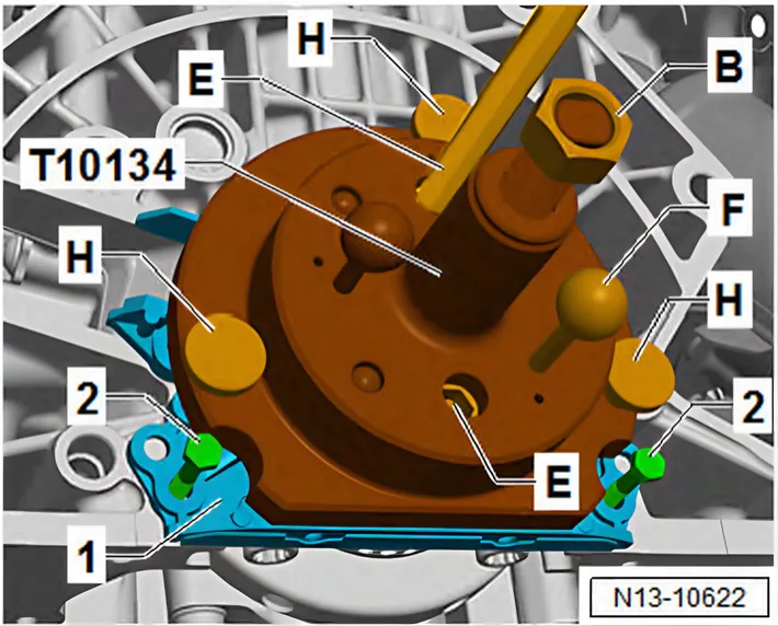
Re-pressing sender wheel:
- Secure assembly tool - T10134- on crankshaft flange -1-.
- Make sure that locating pin of assembly tool - T10134- is properly seated in sender wheel hole.
- Tighten hexagon socket head bolts -E- by hand.
- Push assembly tool - T10134- by hand against sealing flange -1-.
- Screw nut -B- by hand onto threaded spindle until nut rests against assembly tool - T10134-.
- Push guide pin for petrol engines (red knob) -F- into crankshaft flange.
- Screw knurled screws -H- into sealing flange -1-.
- To guide sealing flange, screw two M6×35 mm bolts -2- into cylinder block.
- Tighten nut -B- of assembly tool - T10134- to 40 Nm.
- Check sender wheel installation position on the crankshaft again ⇒ 2.3 Removing and installing sealing flange on gearbox side.
- If the specification is not achieved, tighten nut of assembly tool
- T10134- to 45 Nm.
- Check sender wheel installation position on the crankshaft again ⇒ 2.3 Removing and installing sealing flange on gearbox side.
Installing
- Tighten bolts for sealing flange ⇒ 2.1 Assembly overview - cylinder block, gearbox end.
- Install bottom section of sump ⇒ 1.3 Removing and installing lower part of sump.
- Install upper part of sump ⇒ 1.4 Removing and installing upper part of sump.
- Install intermediate plate ⇒ 2.1 Assembly overview - cylinder block, gearbox end.
- Install flywheel ⇒ 2.2 Removing and installing flywheel.
Torque settings