1.4 TSI engine (EA211) · Crankshaft group · Pistons and conrods
Pistons and conrods – assembly overview and fastening
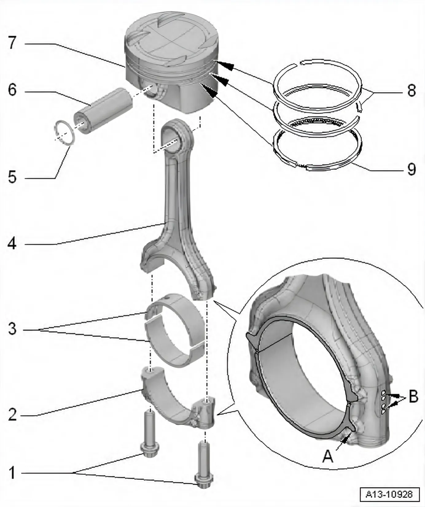
- 1 Bolts
- Renew after removal
- Oil threads and contact surface
- 30 Nm + 90°
- 2 Conrod bearing cap
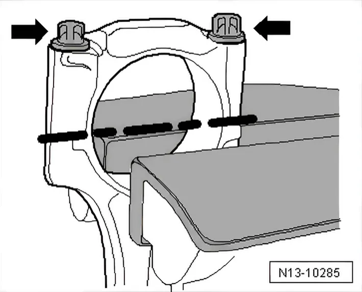
- The conrod bearing cap only fits in one position and only on the appropriate conrod due to the breaking procedure (cracking) separating the cap from the conrod.
- Mark allocation to cylinder and conrod in colour
- B-.
- Installation position: Lug
- A- on conrod bearing cap faces towards pul‐
ley end
- 3 Bearing bushes
- Fitting position ⇒ 4.1 Assembly overview - pistons and conrods
- Renew worn bearing shells
- Ensure firm seating
- 4 Connecting rod
- With industrially cracked conrod bearing cap
- Renew as set only.
- Mark allocation to cylinder and conrod bearing cap in colour -B-.
- Measuring radial clearance ⇒ 4.6 Checking radial clearance of conrods
- Separating new conrod ⇒ 4.2 Separating new conrod.
- Installation position: Lug -A- on conrod bearing cap faces towards pulley end
- 5 Retaining ring
- Qty. 2
- Renew after removal
- 6 Piston pin
- Removing and installing ⇒ 4.3 Removing and installing pistons
- 7 Piston
- Mark installation position and cylinder number ⇒ 4.1 Assembly overview - pistons and conrods.
- Removing and installing ⇒ 4.3 Removing and installing pistons
- Checking piston and cylinder bore ⇒ 4.5 Checking pistons and cylinder bores
- 8 Piston rings
- Compression rings
- Measuring ring gap ⇒ 4.5 Checking pistons and cylinder bores
- Measuring ring-to-groove clearance ⇒ 4.5 Checking pistons and cylinder bores
- Use commercially available piston ring pliers to remove and install.
- Installation position: marking “TOP” or side with lettering towards piston crown
- Offset gaps by 120°
- 9 Piston ring
- Oil scraper ring
- Measuring ring gap ⇒ 4.5 Checking pistons and cylinder bores
- Measuring ring-to-groove clearance ⇒ 4.5 Checking pistons and cylinder bores
- Use piston ring pliers to remove and install.
- Installation position: marking “TOP” or side with lettering towards piston crown
- Offset gap 120° relative to lower compression ring
Installation position and allocation of piston to cylinder
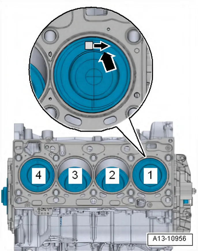
- If worn pistons are to be reinstalled, mark their allocation to the cylinder on the piston crown. Use paint for marking.
- Arrow on piston crown points to pulley end -arrow-.
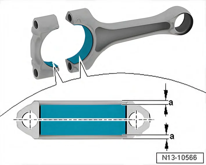
Bearing shells - installation position
- Centre bearing shells on conrod and on conrod bearing cap.
- Distance -a- = distance -a-.
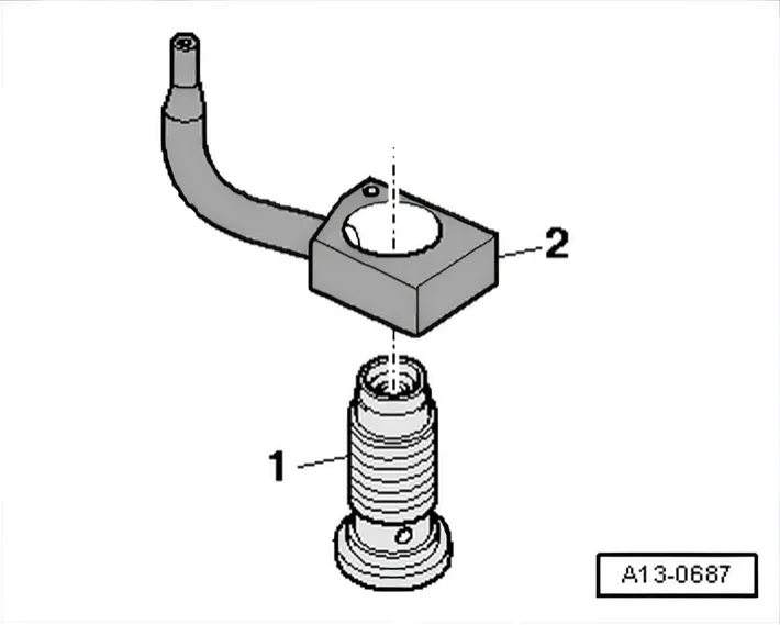
Oil spray jet and pressure relief valve
- 1 Bolt with pressure relief valve, 27 Nm
- 2 Oil spray jet (for cooling of pistons)
- Installation position: align leading edge of oil spray jet arrow with machined surface of cylinder block.
| NOTICE |
Risk of damage to oil spray jets caused by deformation.
- Do not bend oil spray jets.