
1.2 TDI CR engine (EA189) · Lubrication · Balancer shaft module
Removing and installing balance shaft module
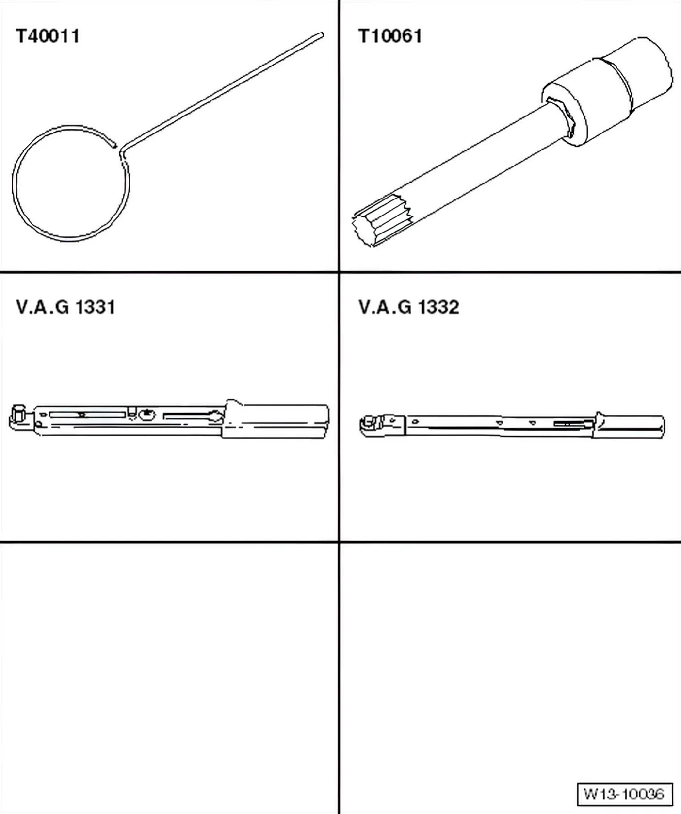
Special tools and workshop equipment required
- Locking pin - T40011-
- Multi-point bit - T10061-
- Torque wrench - V.A.G 1331- (5 - 50 Nm)
- Torque wrench - V.A.G 1332- (40 - 200 Nm)
»Carry out the following work sequence«
Removing
- Toothed belt ⇒ 2.1.1 Removing and installing engine bracket.
- Oil sump ⇒ 1.3 Removing and installing sump.
- Sealing flange at belt pulley end ⇒ 1.9.2 Ancillary bracket (removing and installing).
- Balancer shaft module cover ⇒ Item 1 (page 142).
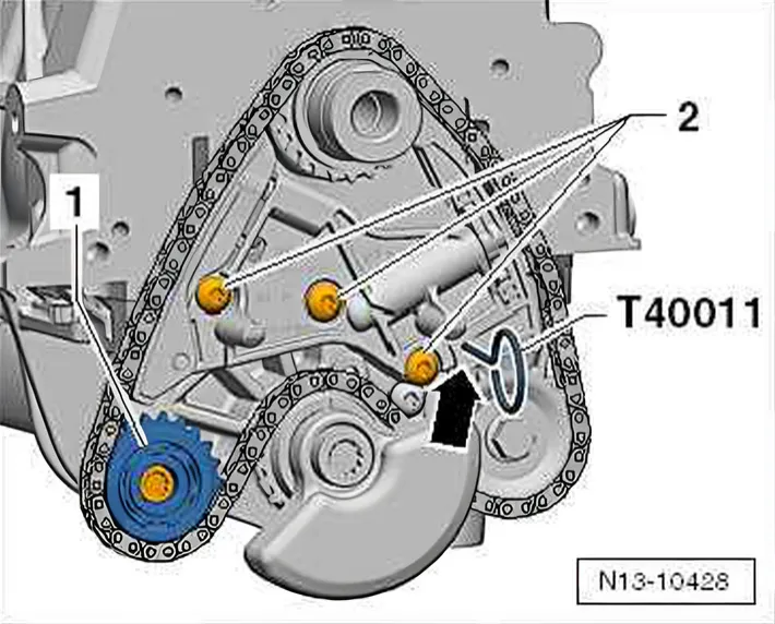
- Lock chain tensioner using locking pin - T40011- -arrow-.
- Unscrew bolt from idler sprocket -1- and remove idler sprocket.
- Unscrew bolts -2- from chain tensioner and remove chain tensioner.
- Remove chain from sprockets and lay chain on a clean surface.
- Unbolt balance shaft module from cylinder block, and place it on a clean surface.
Installing
Specified torque ⇒ 5 Balancer shaft module
- Check chain drive components for wear.
- Screw balance shaft module onto cylinder block hand-tight.
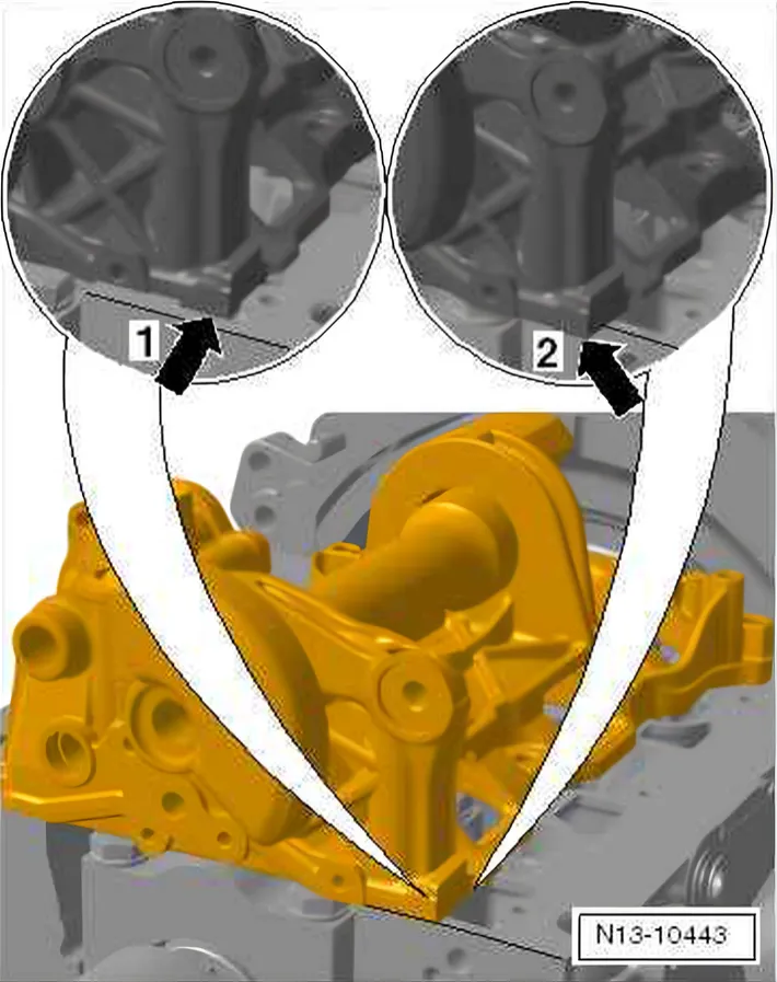
- Align the balance shaft module so that the belt pulley end is flush with the outer edge of the cylinder block.
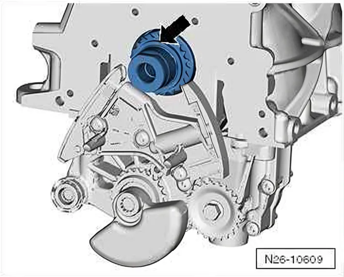
- Check that marking -arrow- on crankshaft sprocket is positioned almost at top.
- Clean chain with a lint-free cloth.
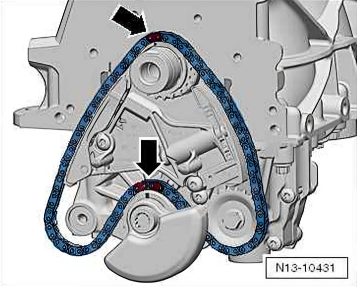
- Fit chain onto chain sprockets of crankshaft, oil pump and balance shaft as shown in illustration.
- Marking on crankshaft sprocket must align with single colour marking on chain link -top arrow- in this case.
- Marking on balance shaft sprocket must be located between 2 colour markings on chain links -bottom arrow-.
- The colour markings are only on the outer plates of the chain. They must be on the outside. This also guarantees the original direction of rotation of the chain.
- Insert guide sprocket into chain, and bolt to balance shaft module at 23 Nm.
- Install chain tensioner.
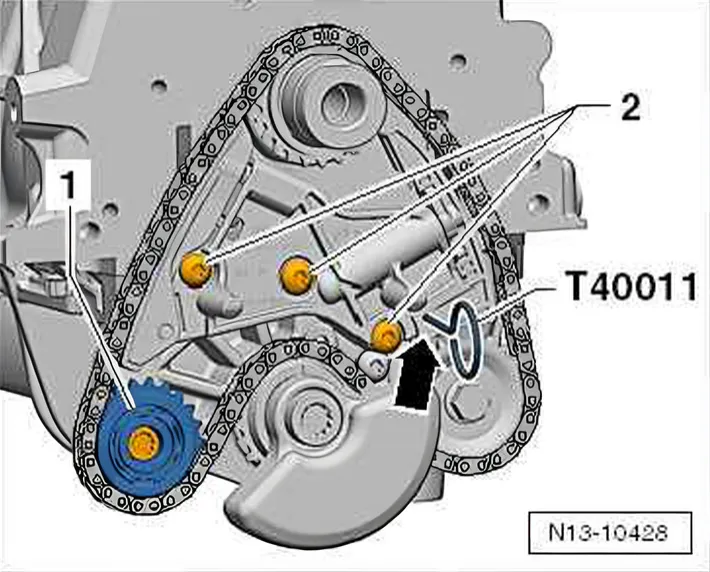
- Replace bolts -2- and tighten as follows.
| 1) | Centre bolt | 8 Nm |
|---|---|---|
| 2) | Bolt on oil pump | 8 Nm |
| 3) | Bolt on guide rail | 8 Nm |
| 4) | Centre bolt | Turn 90° (1/4 turn) further |
| 5) | Bolt on oil pump | Turn 90° (1/4 turn) further |
| 6) | Bolt on guide rail | Turn 90° (1/4 turn) further |
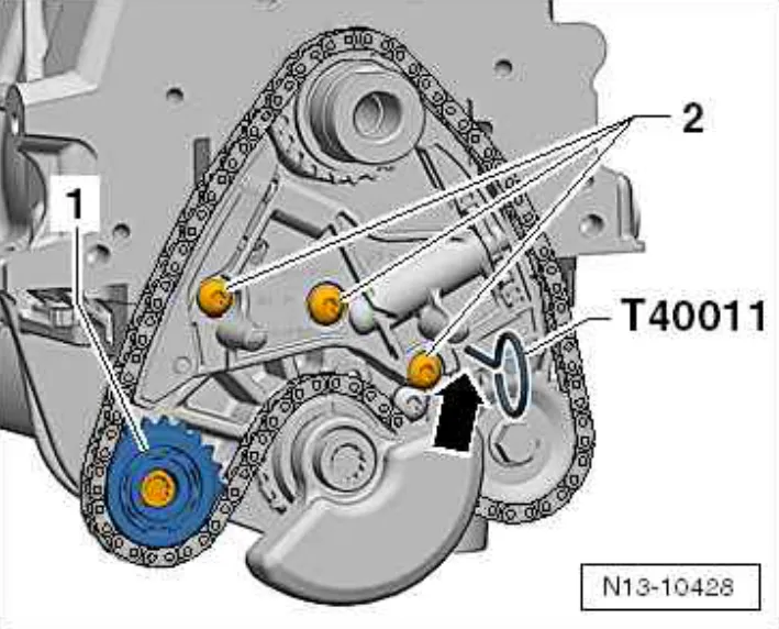
- Remove locking pin - T40011- from chain tensioner.
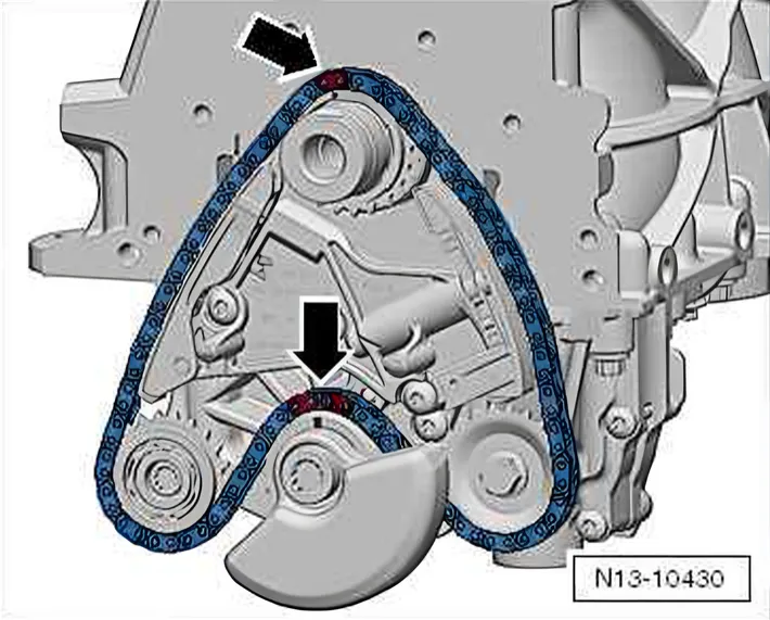
- Check whether markings on sprocket/crankshaft and sprocket/balance shaft are still positioned correctly to colour markings on chain links -arrows-.
- Install sealing flange on belt pulley end ⇒ 1.9.2 Ancillary bracket (removing and installing).
- Install balance shaft cover.
- Install sump ⇒ 1.3 Removing and installing sump.
- Install toothed belt ⇒ 2.1.1 Removing and installing engine bracket.
- Install poly V-belt ⇒ 13 – Crankshaft group.