
1.4 TSI engine (EA211) · Removing and installing engine · Removing and installing engine
Removing engine
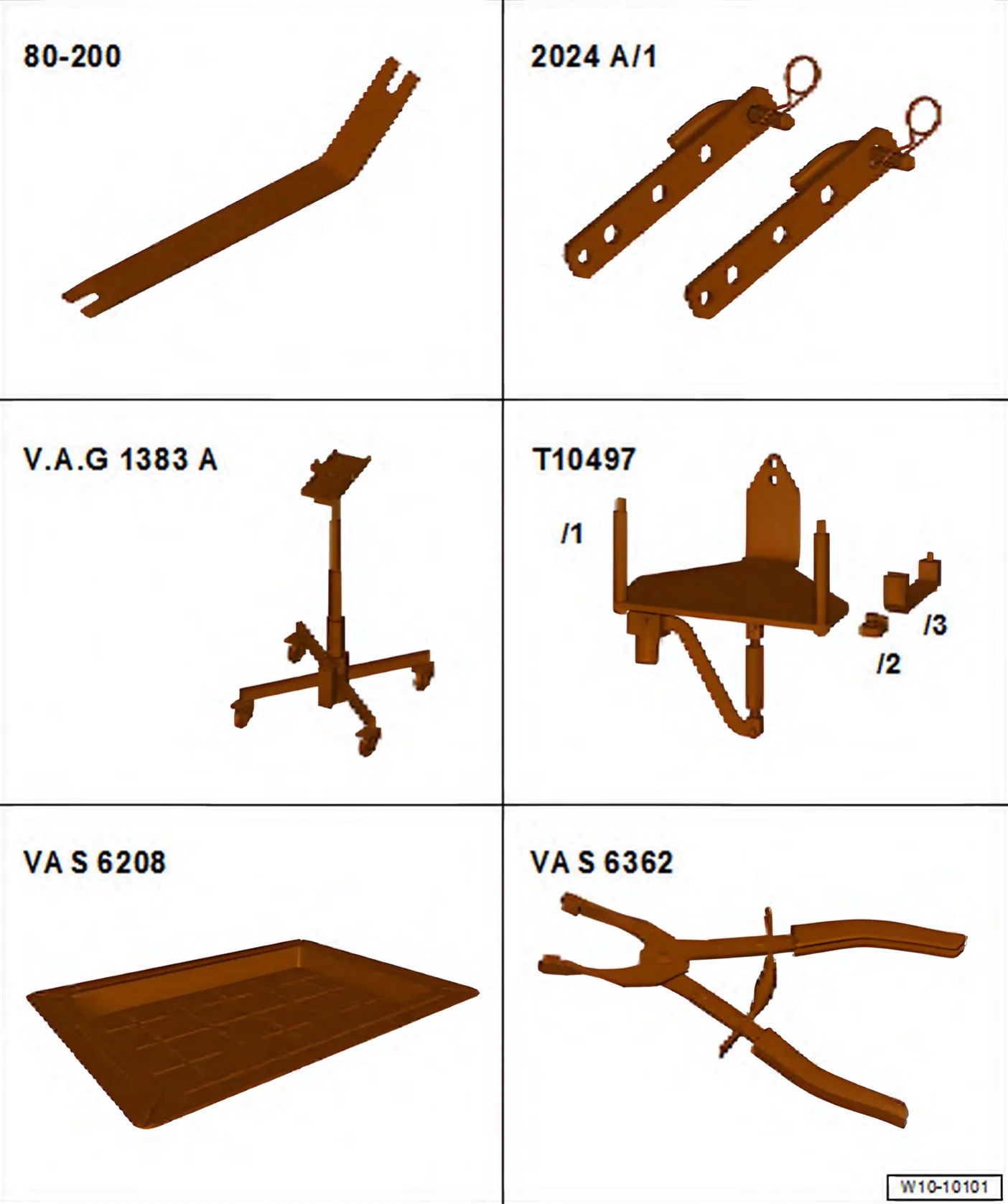
Special tools and workshop equipment required
- Release lever - 80 - 200-
- Engine and gearbox jack - V.A.G 1383 A-
- Engine support - T10497-
- Drip tray for workshop hoist - VAS 6208-
- Spring-type clip pliers - VAS 6362-
- Commercially available stepladder
- Safety glasses
- Safety gloves
Removing
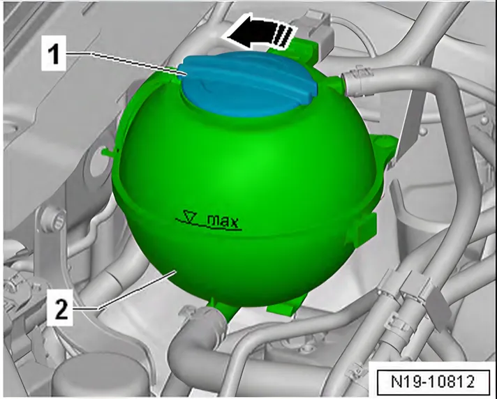
- Carefully open filler cap -1- on coolant expansion tank -2- in -direction of arrow-.
- Remove battery and battery tray ⇒ Electrical system; Rep. gr. 27; Battery; Removing and installing battery tray.
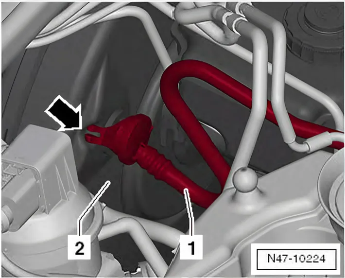
Vehicles with manual gearbox
- Pull vacuum line -1- off brake servo -2-.
- If fitted, release and disconnect connector on vacuum sender on vacuum line.
Continued for all vehicles
- Remove air filter housing ⇒ 3.2 Removing and installing air filter housing.
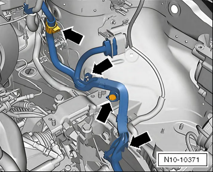
- Carefully loosen wiring harness at its fastening points -arrows-.
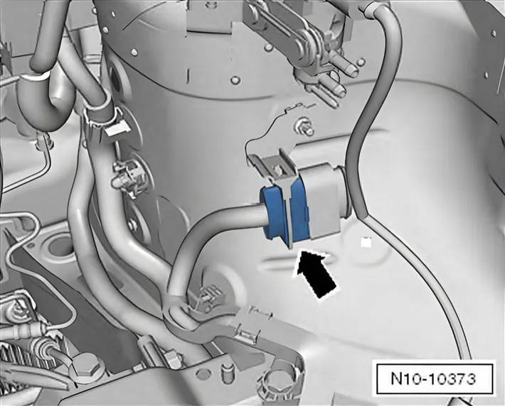
- Release connector -arrow-, pull off and unclip from bracket.
- Release connector from engine control unit and pull off ⇒ 6 Engine control unit.
- Place wiring harness on engine.
- Remove front wheels ⇒ Running gear, axles, steering; Rep. gr. 44; Wheels, tyres; Specified torque for wheel bolts.
- Remove noise insulation ⇒ General body repairs, exterior; Rep. gr. 66; Noise insulation.
- Remove front left and right wheel housing liners ⇒ General body repairs, exterior; Rep. gr. 66; Wheel housing liner.
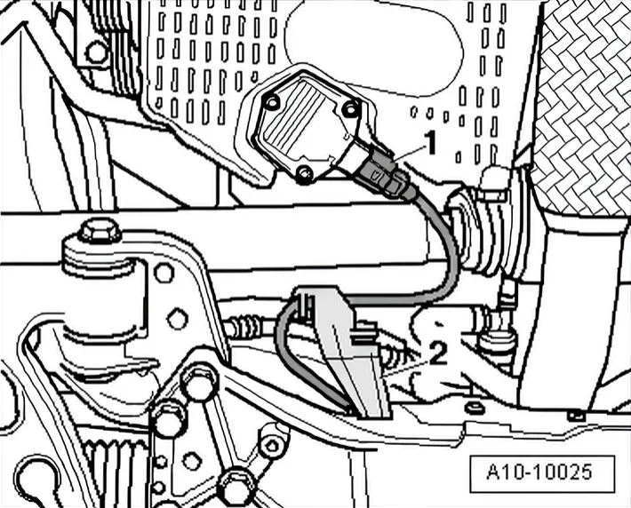
- If fitted, release and pull off connector -1- on oil level and oil temperature sender - G266-.
- Move clear electrical wiring harness, and lay it to one side.
- Remove heat shield for right drive shaft ⇒ Running gear, axles, steering; Rep. gr. 40; Drive shaft; Removing and installing drive shaft heat shield.
- Remove left and right drive shafts ⇒ Running gear, axles, steering; Rep. gr. 40; Drive shaft; Removing and installing drive shaft.
- Remove radiator cowl ⇒ 4.5 Removing and installing radiator cowl with radiator fan.
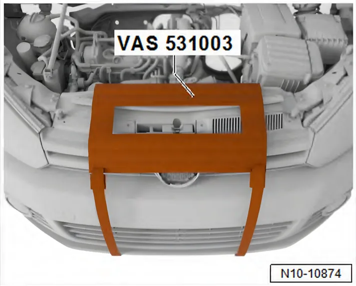
- Attach protective mat - VAS 531003- to vehicle as shown in illustration.
- Drain coolant ⇒ 1.3 Draining and adding coolant.
Vehicles with air conditioner compressor:
- Remove poly V-belt ⇒ 1.3 Removing and installing poly-V belt.
- Separate connector -1- on air conditioning compressor regulating valve - N280-.
- Remove air conditioner compressor with refrigerant lines connected from engine ⇒ Heating, air conditioning; Rep. gr. 87; Air conditioner compressor; Removing air conditioner compressor from and installing to bracket.
- Detach air conditioner compressor from bracket (refrigerant hoses remain connected) and tie up to right side.
- Do NOT stretch, kink or bend refrigerant lines and hoses while doing so.
Continued for all vehicles
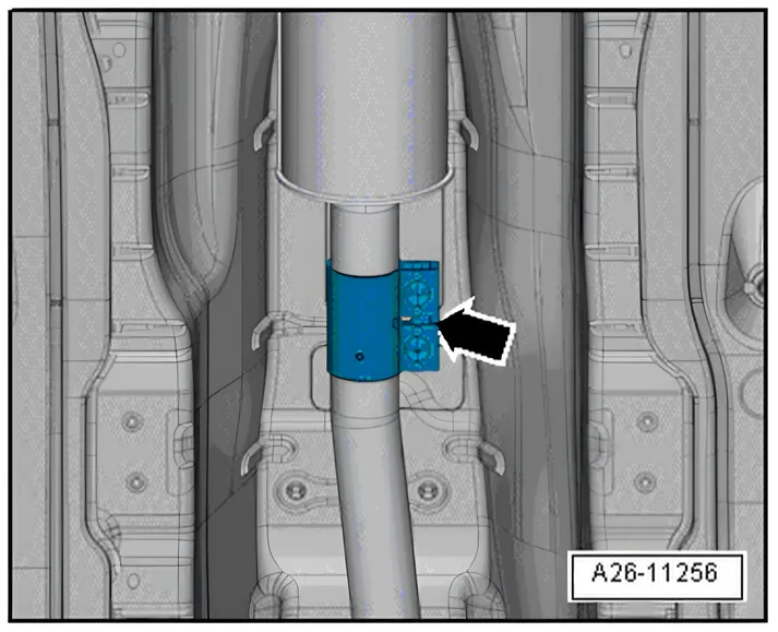
- Loosen clamp -arrow-, and push it to rear.
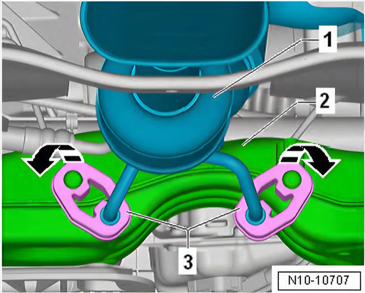
- Detach exhaust hangers -3- in -direction of arrow- from subframe -2-.
- Lower exhaust system -1- until it rests on subframe -2-.
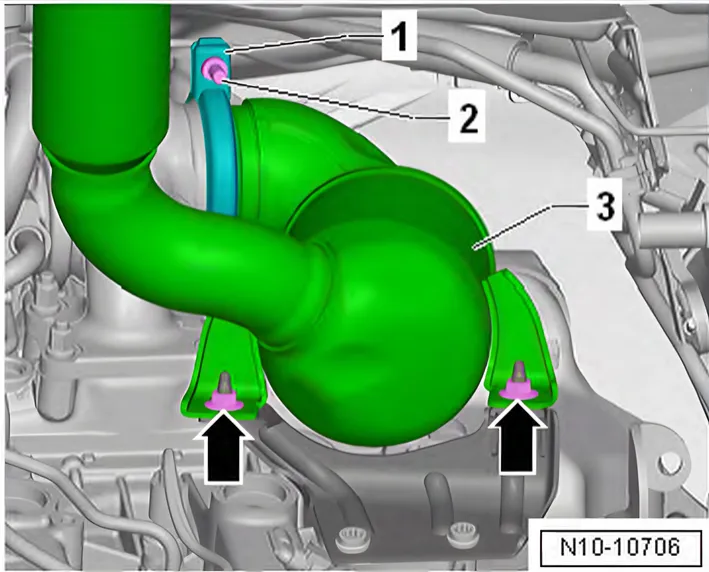
- Unscrew bolt -2-.
- Remove screw-type clip -1-.
- Unscrew nuts -arrows- and tie up catalytic converter -3-.
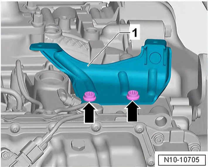
- Unscrew bolts -arrows- and remove bracket -1-.
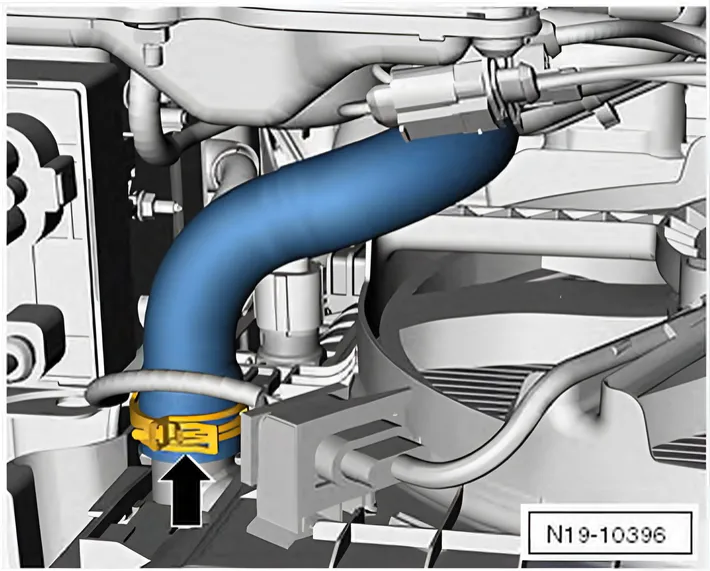
- Open spring-type clip -arrow- and pull off coolant hose downwards.
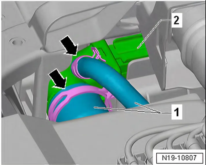
- Open spring-type clips -arrows-.
- Pull coolant hose -1- off radiator -2-.
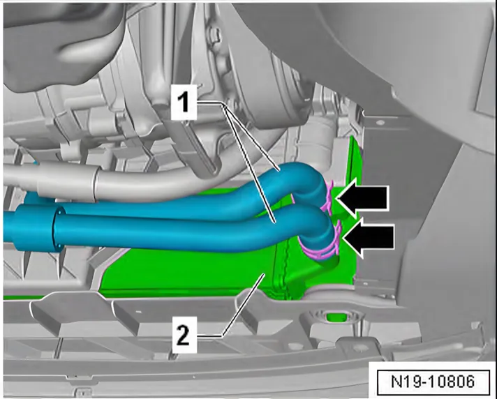
- Open spring-type clips -arrows-.
- Pull coolant hoses -1- off water radiator for charge air cooling circuit -2-.
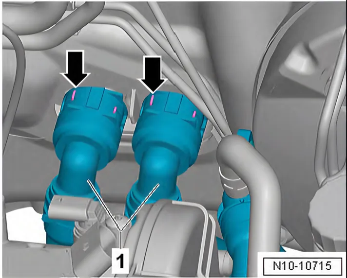
- Release retaining clips -arrows-.
- Pull coolant hoses -1- off heat exchanger for heater unit.
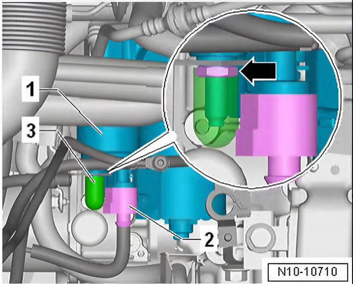
- Release and pull off connector -2- on starter -1-.
- Pull off protective cap -3-.
- Unscrew nut -arrow- and remove line from starter -1-.
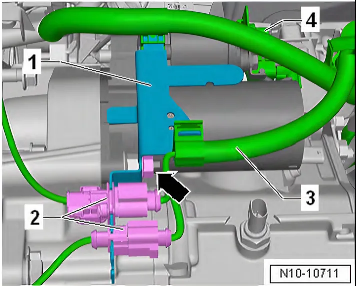
- Release and pull off connectors -2-.
- Unclip connectors -2- from bracket -1-.
- Unclip wires -3- and -4- from bracket -1-.
- Unscrew nuts -arrow-.
- Remove bracket -1- from gearbox.
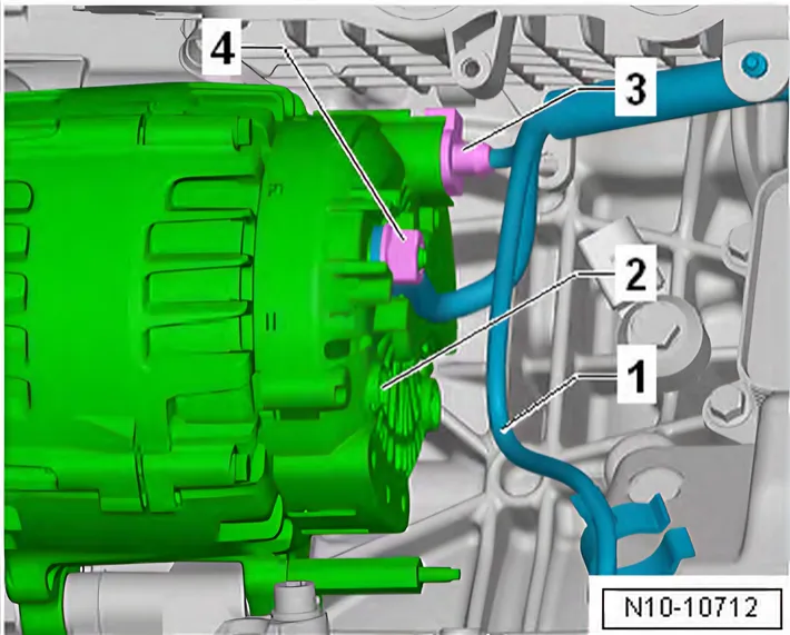
- Release and pull off connector -3- on alternator -2-.
- Unscrew nut -4-.
- Remove wire -1- from alternator -2-.
- Lay wiring harness -1- on coolant hose to one side.
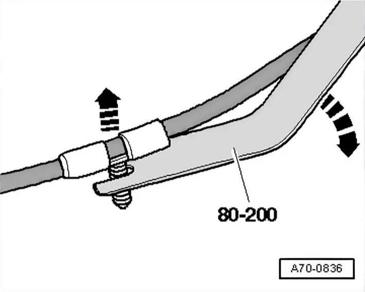
- Lay lower wiring harness on intake manifold to one side.
- Use removal lever - 80 - 200- to do this.
Vehicles with manual gearbox
- Release and pull off connectors on gearbox.
- Remove selector mechanism from gearbox ⇒ Rep. gr. 34; Selector mechanism; Removing and installing selector mechanism.
- Remove clutch slave cylinder ⇒ Rep. gr. 30; Clutch mechanism; Removing and installing clutch slave cylinder.
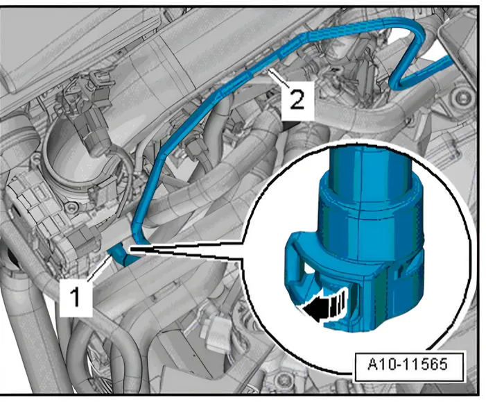
Vehicles with dual clutch gearbox
- Release catch -arrow- and disconnect vacuum hose -1-.
- Move clear vacuum hose at air intake pipe -2-.
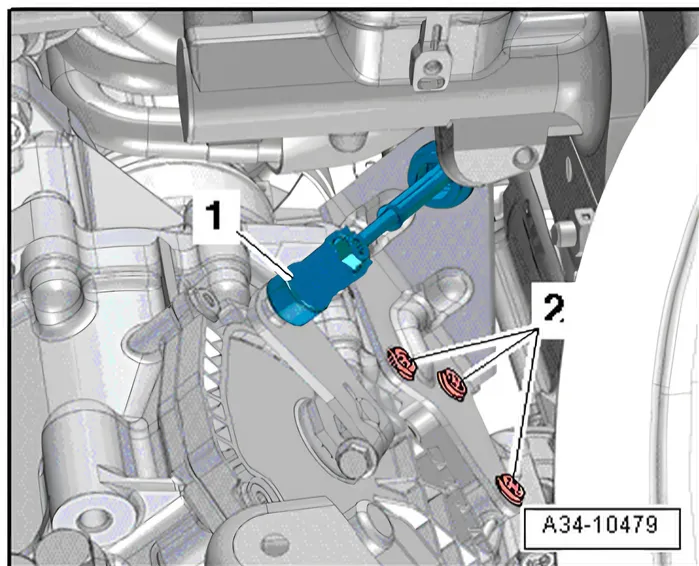
- Remove selector lever cable -1- ⇒ Rep. gr. 34; Removing and installing gearbox.
- Unscrew bolts -2- on gearbox.
- Lay selector lever cable with retainer to one side.
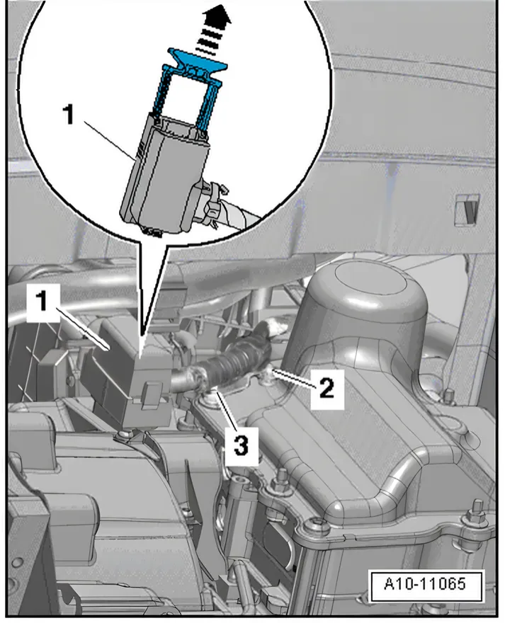
- Release and pull off connector -1- of mechatronic unit in -direction of arrow-.
- Unscrew bolts -2- and -3-.
- Remove retainer with wiring harness and lay them to one side.
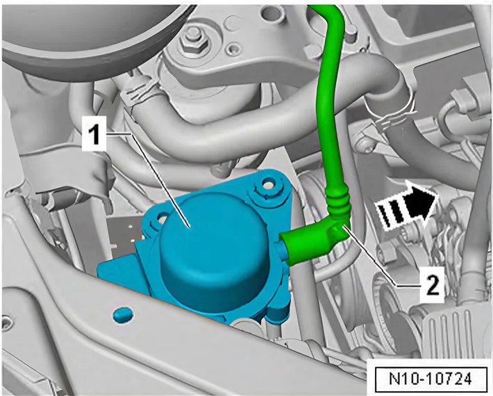
- Pull vacuum line -2- in direction of -arrow- off vacuum pump for brakes - V192- -1-.
- Lay vacuum line -1- to one side.
Continued for all vehicles
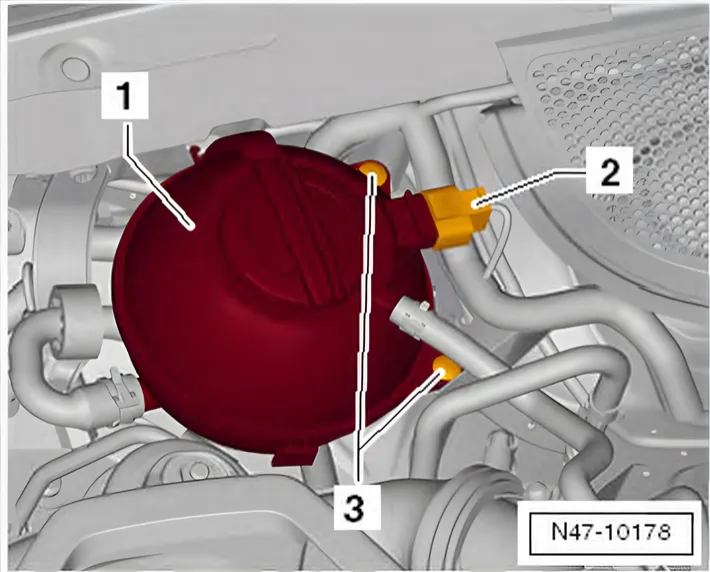
- Release connectors -2- and pull off.
- Unscrew securing bolts -3-.
- Place coolant expansion tank -1- on engine.
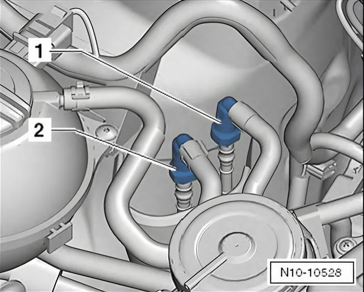
- Disconnect fuel supply line -1- and line to activated charcoal filter solenoid valve 1 - N80- -2-. Disconnect plug-in connectors ⇒ Rep. gr. 20; Plug-in connectors; Disconnecting plugin connectors.
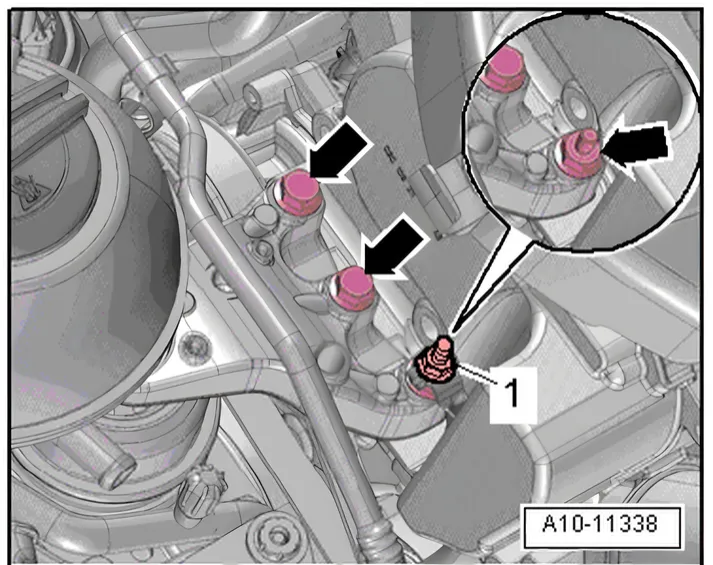
- Unscrew earth wire -1-.
- Unscrew bolts -arrows- on engine mounting approx. 2 turns.
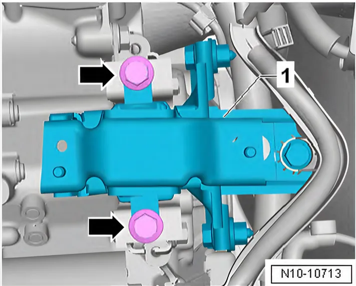
- Unscrew securing bolts -arrows- on gearbox mounting by approx. 2 turns.
- Remove pendulum support ⇒ 2.4 Removing and installing pendulum support.
- Apply clamping piece T10497/2 at housing rib on cylinder block, as shown in illustration.
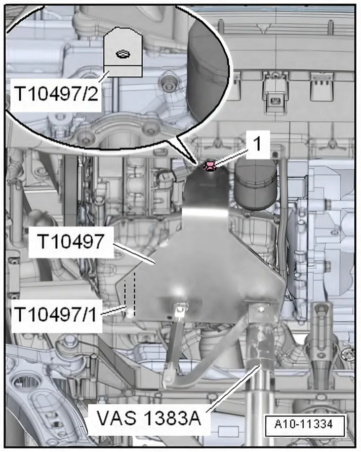
- Position engine support T10497 with pin T10497/1 on cylinder block.
- Screw in bolt -1- through hole “B” in engine support T10497 and tighten it to 20 Nm.
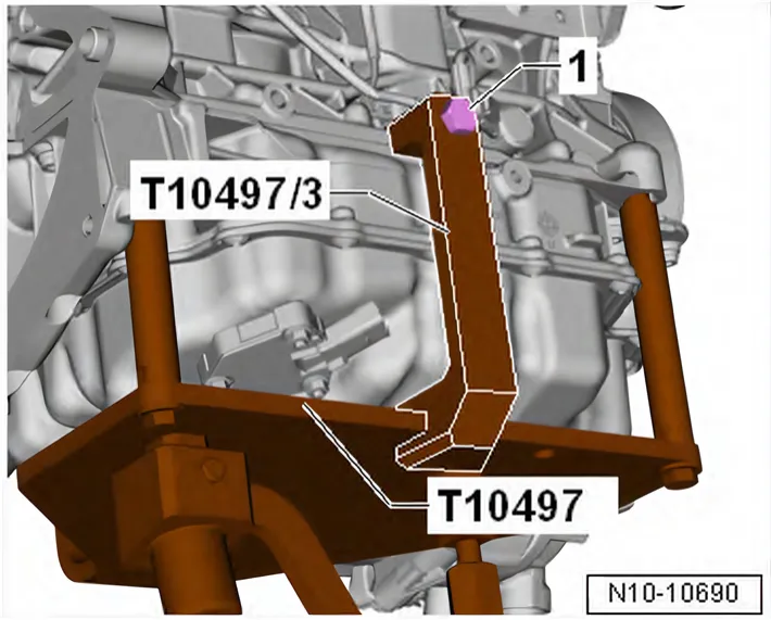
- Fit adapter - T10497/3- to engine support - T10497- and tighten bolt -1- to 20 Nm.
- Insert engine and gearbox jack - V.A.G 1383 A- in engine support T10497, and raise engine/gearbox assembly slightly.
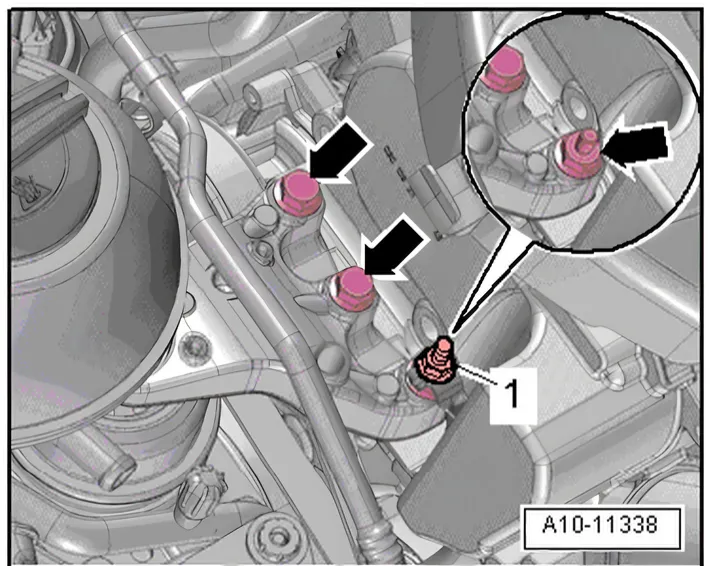
- Remove bolts -arrows- for engine mounting.
- Unscrew securing bolts -arrows- from gearbox mounting.
- Check that all vacuum lines and electrical wiring between engine, gearbox, subframe and body have been detached.
- When lowering, carefully guide engine/gearbox assembly with assembly carrier out of engine compartment.
- First lower engine/gearbox assembly slightly.
- Then push gearbox end of engine/gearbox assembly forwards and only then lower further.