
1.2 TDI CR engine (EA189) · Cylinder head, valve gear · Toothed belt drive
Removing, installing and tensioning toothed belts
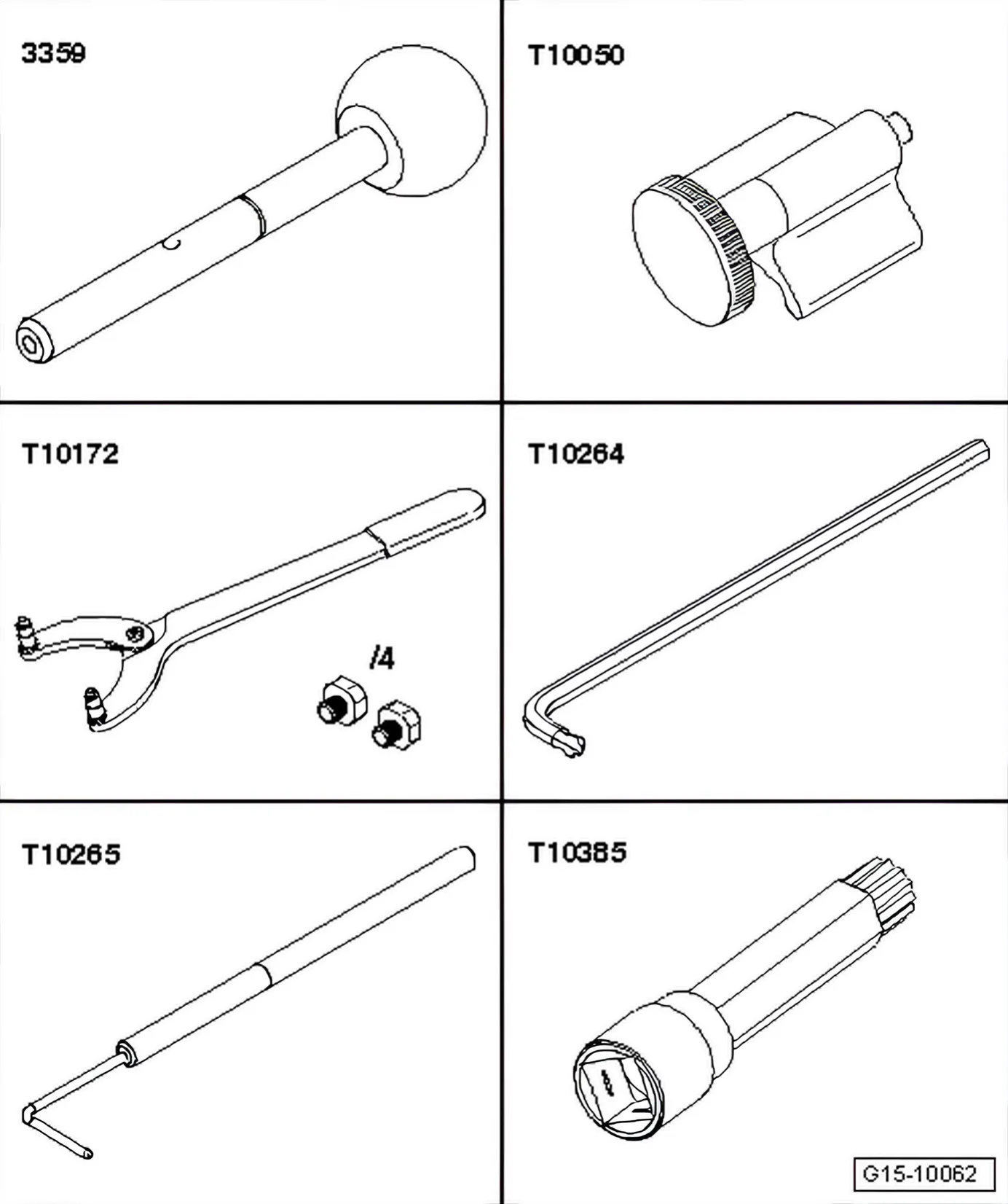
Special tools and workshop equipment required
- 2x diesel injection pump locking pin - 3359-
- Crankshaft stop - T10050-
- Counter-hold tool - T10172-
- Angled screwdriver - T10264-
- Locking tool - T10265-
- Socket XZN 10 - T10385-
Not illustrated:
- Torque wrench - V.A.G 1331-
- Torque wrench - V.A.G 1332-
2.2.1 Removing
»Carry out the following work sequence«
- Engine cover panel ⇒ 3 Engine cover panel
- With ignition switched off, disconnect battery. ⇒ Electrical system; Rep. gr. 27; Disconnecting and reconnecting batteries.
- Noise insulation ⇒ General body repairs, exterior; Rep. gr. 50; Body - front; Assembly overview - noise insulation.
- Poly V-belt ⇒ 13 – Crankshaft group.
- Remove charge air pipe »cold« side ⇒ 2.3.2 Removing and installing charge air pipe »hot« side.
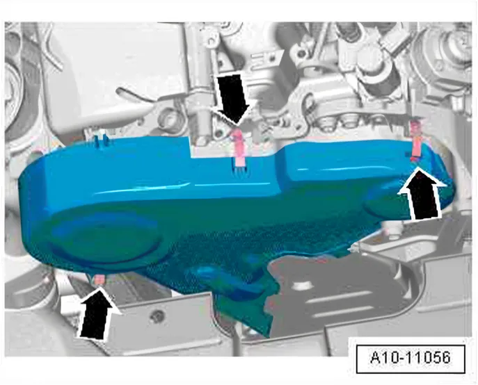
- Remove upper timing belt guard by detaching clips -arrows-.
- Remove front right wheel housing liner.
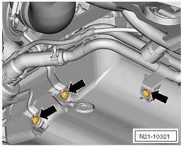
- Unscrew bolts -arrows-.
- Press coolant lines aside slightly.
- Remove vibration damper ⇒ 1.7.1 Removing and installing tensioning element for poly V-belt.
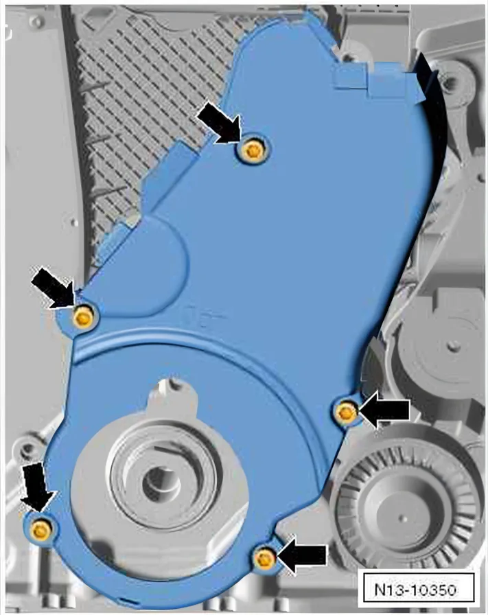
- Unscrew bolts -arrows-.
- Remove lower toothed belt guard.
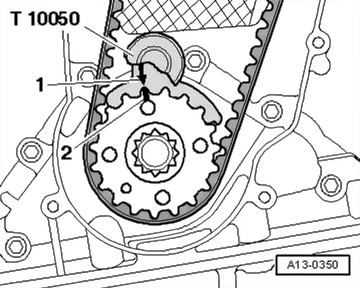
- Turn engine to TDC and lock crankshaft pulley in position with crankshaft stop - T10050-. Fit the crankshaft stop in the teeth from the face side of the toothed belt pulley.
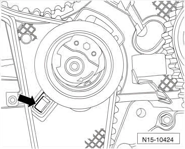
- The mark -2- on the toothed pulley and the arrow -1- on the crankshaft stop - T10050- must align -arrow-. When doing this, the pin of the crankshaft stop must engage in the drilling of sealing flange.
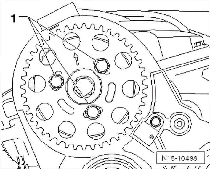
The arrow on the camshaft pulley must be at almost »12 o'clock«.
- Mark direction of rotation of toothed belt.
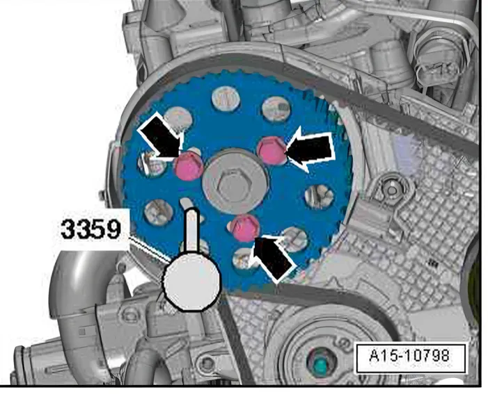
- Loosen bolts -arrows- approx. 90° for camshaft toothed belt pulley.
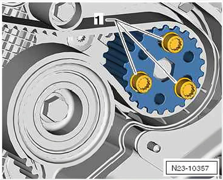
- Loosen bolts -1- approx. 90° for high-pressure pump toothed belt pulley using bit XZN 10 - T10385-.
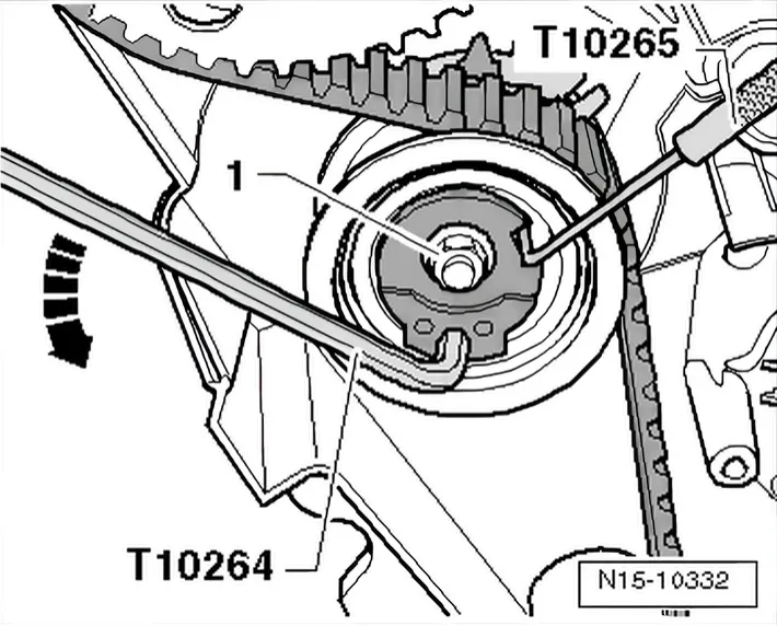
- Loosen securing nut of tensioning roller -1- and turn tensioning roller eccentric using socket - T10264- counter-clockwise -arrow- until tensioning roller can be locked with locking pin - T10265-.
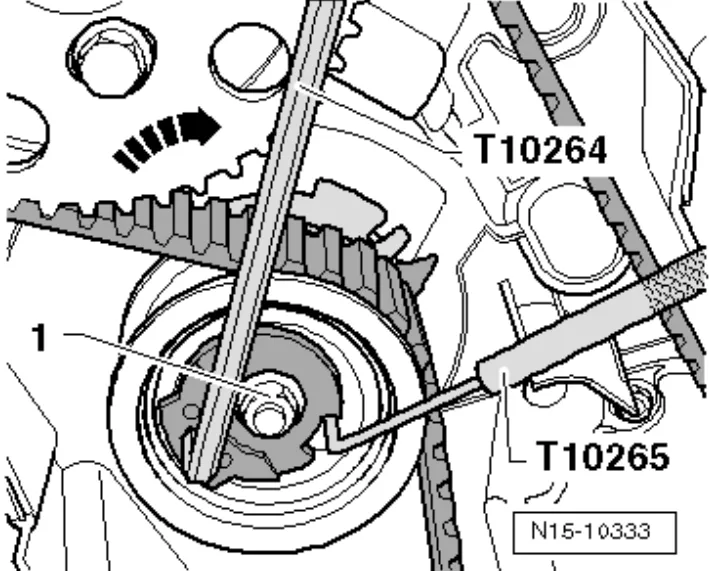
- Turn eccentric of tensioning roller clockwise -arrow- to stop. Tighten securing nut -1- hand-tight.
- Remove toothed belt first from idler pulley and then from remaining toothed belt pulleys.
2.2.2 Installing (adjusting valve timing)
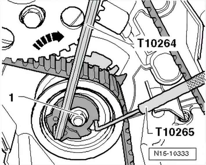
- Tensioning roller must be locked with locking tool - T10265- and secured to right stop.
- Crankshaft is locked using crankshaft stop - T10050-.
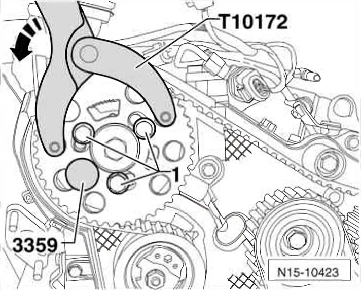
- Lock the camshaft hub with locking pin - 3359-. To do this, insert locking pin through outer free elongated hole into hole in cylinder head.
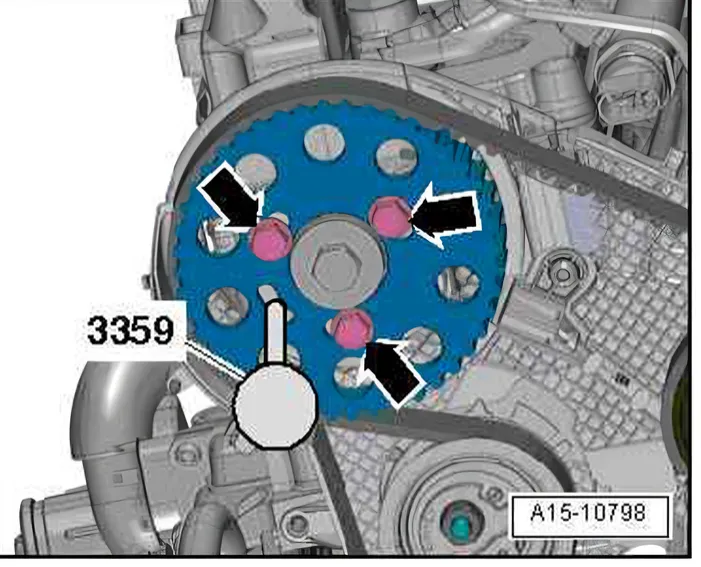
- Loosen the hand-tightened bolt again.
Bolts -arrows- screwed in loosely.
It should just be possible to turn camshaft toothed belt pulley without axial movement.
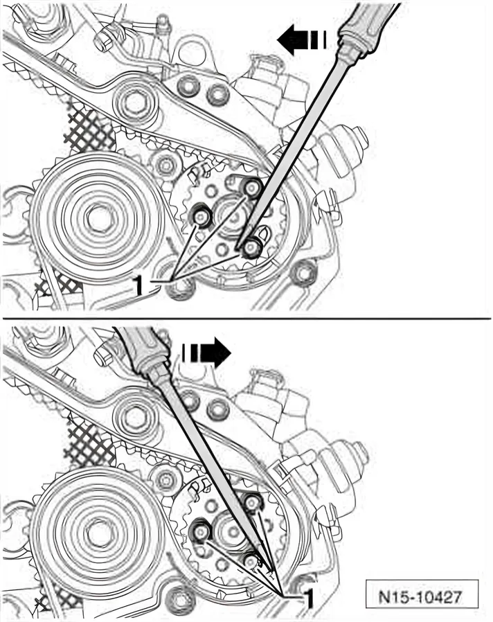
Positioning hub of high-pressure pump
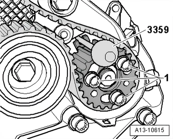
- Lock the camshaft hub with locking pin - 3359-. To do this, push locking pin into adjustment hole outside toothed belt pulley.
Loosely tightened bolts -1-.
It should just be possible to turn high-pressure pump toothed belt pulley without axial movement.
- Turn camshaft sprocket and toothed belt sprocket of highpressure pump in their elongated holes clockwise to stop.
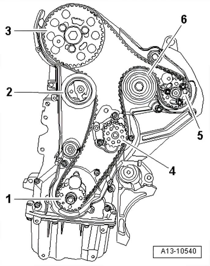
- Fit toothed belt in sequence described:
- 1 Crankshaft pulley
- 2 Tensioning pulley
- 3 Camshaft toothed belt pulley
- 4 Coolant pump toothed belt pulley
- 5 High-pressure pump toothed belt pulley
- 6 Idler roller
- Loosen belt tensioner securing nuts and pull out locking tool - T10265-.
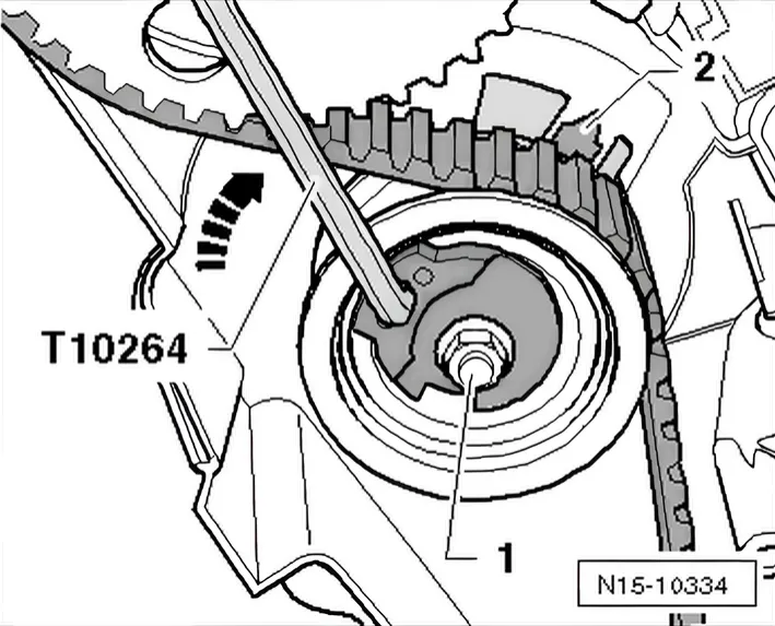
- Carefully turn eccentric of tensioning roller clockwise using angle driver - T10264-. Indicator -2- must be roughly past the centre of the gap in the base plate (corrects itself during pretensioning).
Ensure that securing nut -1- does not turn as well.
- Hold tensioning roller in this position. Tighten tensioning roller securing nuts as follows: 20 Nm and turn 45° further.
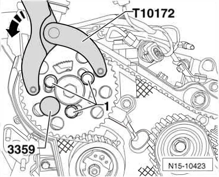
- Fit counterhold - T10172- as shown. Press counterhold - T10172- in direction of arrow and keep camshaft sprocket in pretensioning position.
- In this position, first tighten securing bolts -1- of camshaft pulley and of toothed belt pulley for high-pressure pump by hand, and then tighten them to 20 Nm.
- Remove locking pins - 3359- and crankshaft stop - T10050-.
- Turn crankshaft at least two rotations in engine direction of rotation and set to just before TDC No. 1 cylinder.
- Place crankshaft stop - T10050- on the crankshaft's toothed belt pulley again.
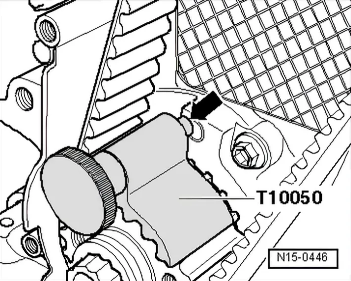
- Now turn crankshaft in engine direction of rotation until crankshaft stop pin -arrow- engages in sealing flange whilst turning.
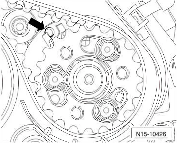
- Check whether:
- Camshaft hub can be locked with locking pin - 3359-.
- Tensioning roller indicator is centred or maximum 5 mm to right of base plate notch.
If camshaft hub cannot be locked:
- Pull crankshaft stop - T10050- back until pin uncovers hole.
- Turn crankshaft out slightly past TDC by turning it in the opposite direction of engine rotation.
- Now turn crankshaft slowly in direction of engine rotation until camshaft hub can be secured in position.
- After locking, loosen securing nuts of camshaft pulley.
If pin of crankshaft stop - T10050- is standing on left next to hole:
- Turn crankshaft in engine direction of rotation until crankshaft stop pin engages in sealing flange whilst turning.
- First, tighten securing bolts of camshaft toothed belt pulley hand-tight, then tighten them to 20 Nm.
If pin of crankshaft stop - T10050- is standing on right next to hole:
- Turn crankshaft slightly counter to engine direction of rotation again.
- Turn crankshaft in engine direction of rotation until crankshaft stop pin arrow engages in sealing flange whilst turning.
- First, tighten securing bolts of camshaft toothed belt pulley hand-tight, then tighten them to 20 Nm.
Continuation
- Remove locking pin - 3359- and crankshaft stop - T10050-.
- Turn crankshaft at least two rotations in engine direction of rotation and set to just before TDC No. 1 cylinder.
- Repeat check.
- If camshaft hub can be secured in position, tighten securing bolts as follows:
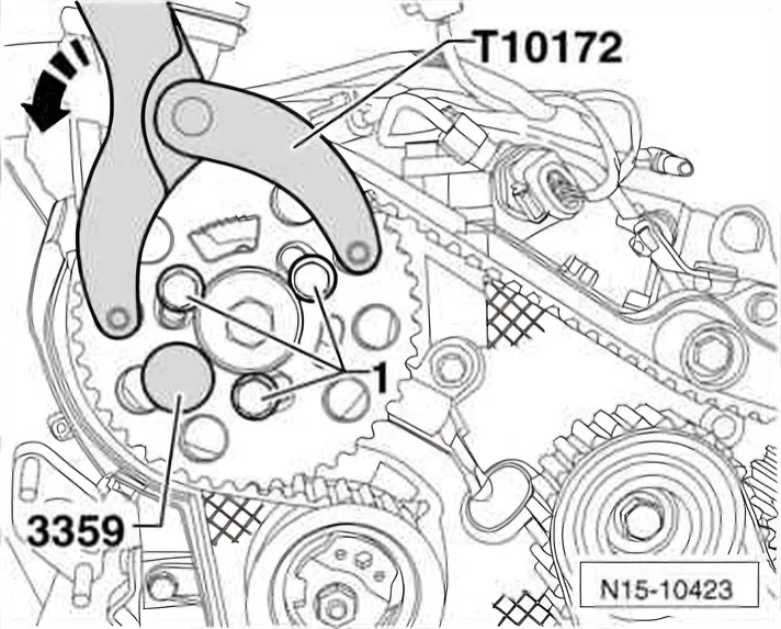
- Camshaft sprocket: 45° further. Counterhold with counterhold - T10172- and adapters - T10172/4-.
- Install middle and lower toothed belt guards.
- Install vibration damper/belt pulley. Tighten to specified torque 10 Nm and then turn a further 90°.
- Install poly V-belt ⇒ 13 – Crankshaft group.
- Install upper toothed belt guard.
Further assembly is basically a reverse of the dismantling sequence. During this procedure, observe the following:
- Ensure fuel hoses are seated correctly.
- Do not interchange supply line and return line (return line blue or with blue marking, supply line white).
- Install wheel housing liner.
- Install noise insulation ⇒ General body repairs, exterior; Rep. gr. 50; Body - front; Assembly overview - noise insulation.