
1.2 TDI CR engine (EA189) · Cylinder head, valve gear · Valve gear
Inlet and exhaust valves
⇒ 3.4.4 Renewing valve stem seals
⇒ 3.4.4 Renewing valve stem seals
⇒ 3.4.5 Renewing valve stem seals with cylinder head removed
3.4.1 Valve dimensions
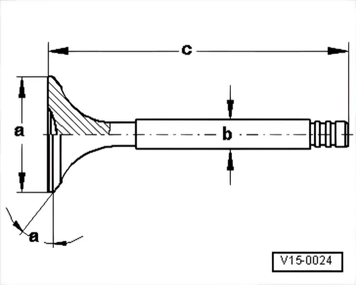
| Dimension | Inlet valve | Outlet valve |
|---|---|---|
| ∅ a mm | 26.50 … 26.70 | 24.4 … 24.60 |
| ∅ b mm | 5.968 … 5.982 | 5.958 … 5.972 |
| c mm | 99.30 | 99.10 |
| α ∠° | 45 | 45 |
3.4.2 Reworking valve seats
3.4.3 Checking valve guides
Special tools and workshop equipment required
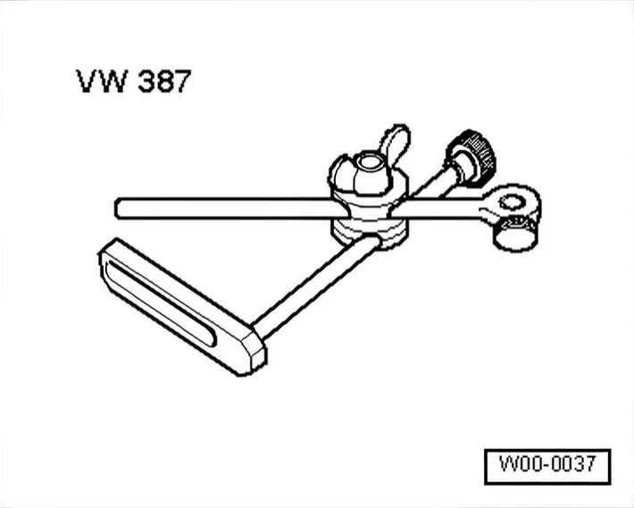
- Universal dial gauge holder - VW 387-
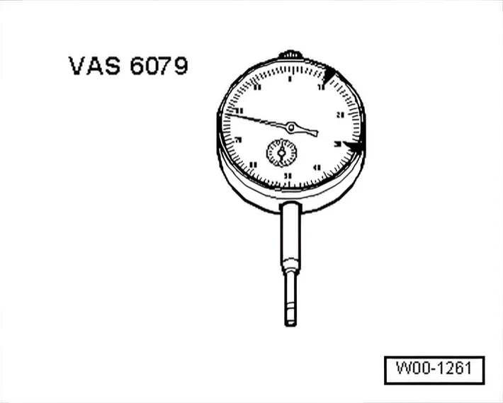
- Dial gauge
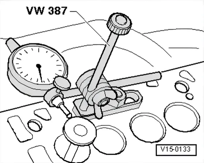
- Insert new valve in guide. The end of the valve stem must be flush with the guide. On account of differing stem diameters, only use inlet valve in inlet guide and exhaust valve in exhaust guide.
- Determine rock. Wear limit: max. 1.3 mm
- Cylinder head must be renewed if rock exceeds wear limit.
3.4.4 Renewing valve stem seals
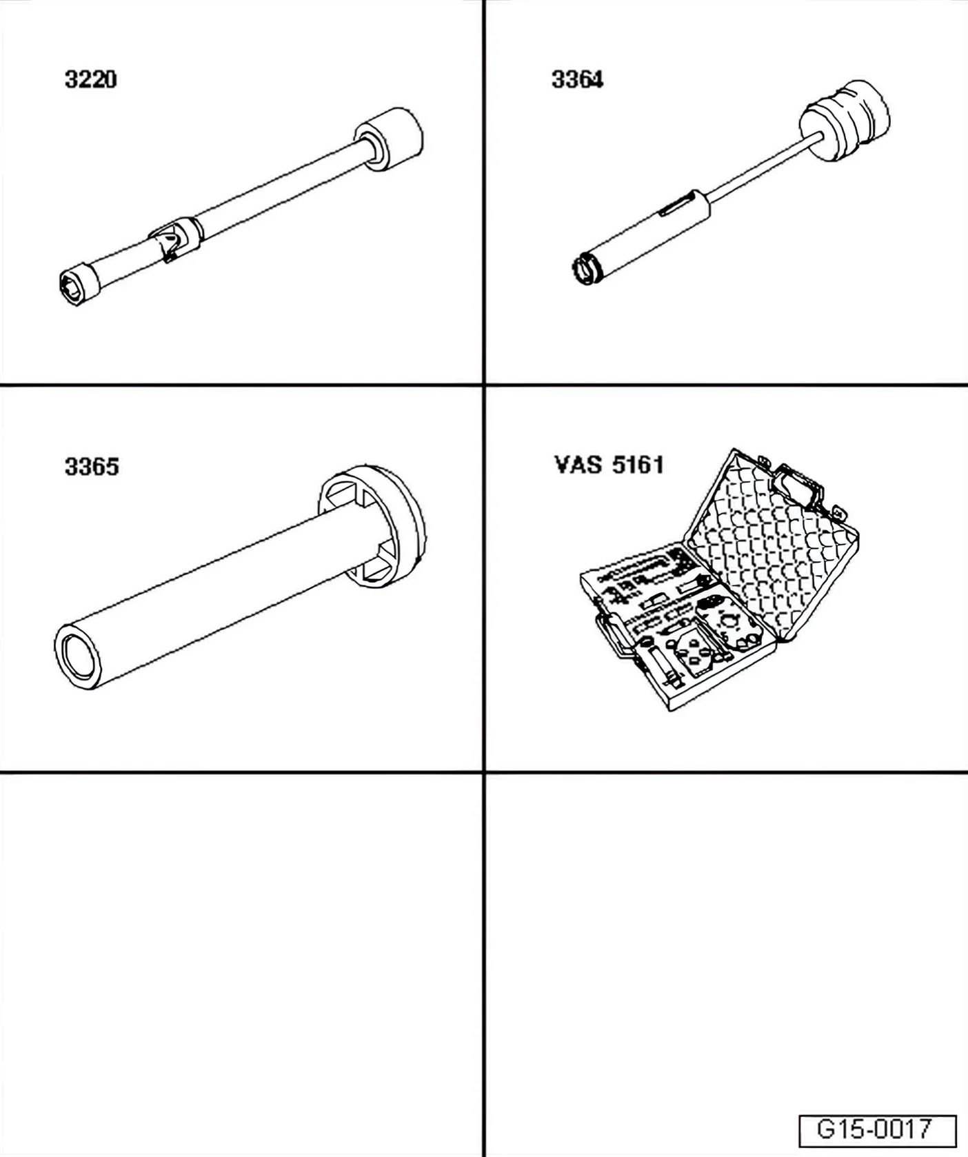
Special tools and workshop equipment required
- 10 mm jointed spanner - 3220-
- Valve stem seal puller - 3364-
- Valve stem seal fitting tool - 3365-
- Removal and installation device for valve cotters - VAS 5161- with guide plate - VAS 5161/23- and knurled spacer ring - VAS 5161/23-1-
Removing
»Carry out the following work sequence«
- Remove all glow plugs using jointed spanner - 3220-. ⇒ 28 – Glow plug system
- Remove camshafts ⇒ 3.5 Removing and installing camshafts.
- Remove roller rocker fingers, note installation position of roller rocker fingers ⇒ Item 7 (page 97).
- Place guide plate - VAS 5161/23- onto cylinder head.
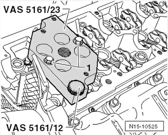
- Secure guide plate on intake manifold side using knurled screw - VAS 5161/12- and M6 bolts -1-.
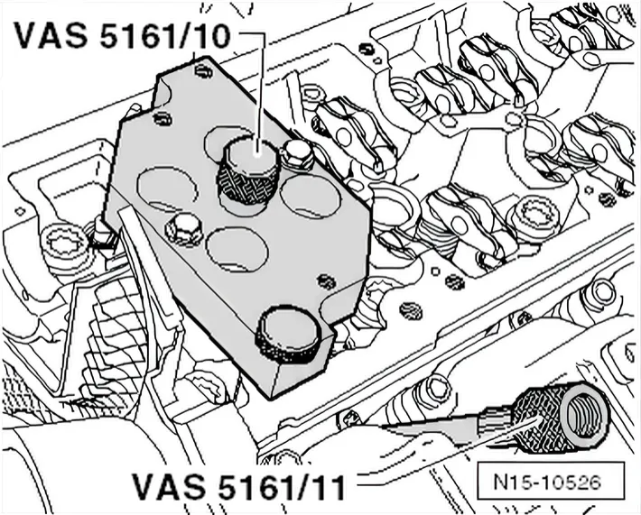
- Screw sealing bolt - VAS 5161/10- into the guide plate.
- Screw adapter - VAS 5161/11- into the respective glow plug thread hand-tight.
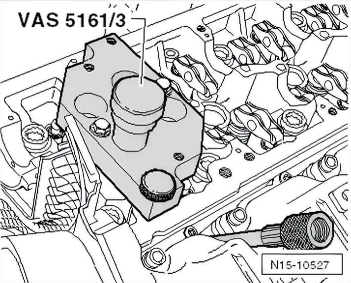
- Insert punch - VAS 5161/3- into guide plate and use a plastic hammer to knock loose the firmly seated valve cotters.
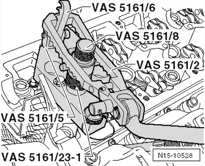
- Screw attachment fork - VAS 5161/5- with ratchet piece - VAS 5161/6- into guide plate.
- Push knurled spacer ring - VAS 5161/23-1- onto the assembly cartridge - VAS 5161/8-.
- Connect adapter - VAS 5161/11- to compressed air using a commercially available intermediate piece. Leave constantly under pressure.
- Minimum pressure: 6 bar.
- Attach pressure fork - VAS 5161/2- to ratchet piece, press assembly cartridge down.
- At the same time, turn knurled screw of assembly cartridge clockwise until tips engage in valve cotters.
- Move knurled screw back and forth slightly to press apart valve cotters and capture them in the assembly cartridge.
- Release pressure fork.
- Remove assembly cartridge with knurled spacer ring, valve plate and valve spring.
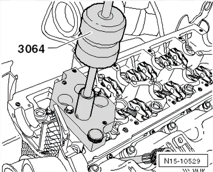
- Pull off valve stem seals using valve stem seal puller - 3364-.
Installing
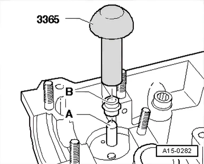
- Lightly oil sealing lip of valve stem oil seal and valve stem.
- Carefully push valve stem oil seal on valve stem -A-.
- Carefully press valve stem oil seal onto valve guide using valve stem seal fitting tool - 3365-.
- If necessary, use a plastic head hammer and tap lightly on fitting tool until valve stem seal is fitted to stop.
- Insert valve spring and valve plate into cylinder head.
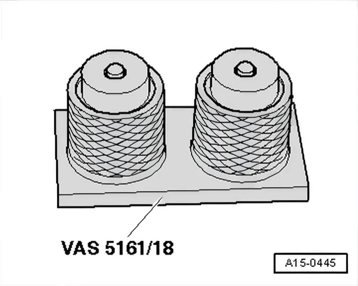
- If valve cotters have been removed from assembly cartridge, they need to be put into insertion device - VAS 5161/18- first.
- Press assembly cartridge onto insertion device from above and pick up valve cotters.
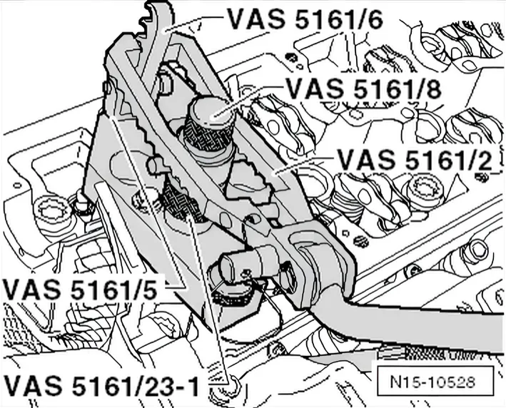
- Insert installation cartridge - VAS 5161/8- into guide plate again.
- Push down pressure fork, and pull knurled screw upwards while turning to left and right - this will insert the valve cotters.
- Reduce pressure on pressure fork whilst pulling on knurled screw.
Further installation is carried out in the reverse order of removal; note the following:
- Install camshafts ⇒ 3.5 Removing and installing camshafts.
- Installing ceramic glow pin plugs ⇒ 28 – Glow plug system.
3.4.5 Renewing valve stem seals with cylinder head removed
Special tools and workshop equipment required
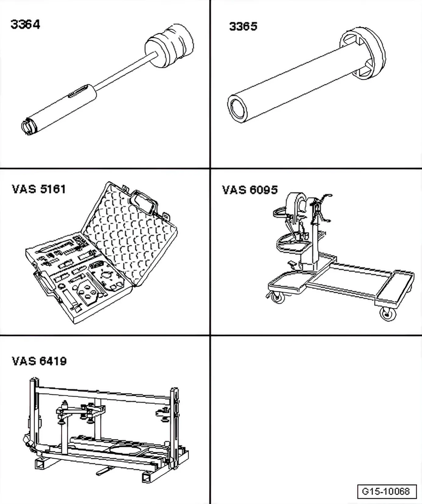
- Valve stem seal puller - 3364-
- Valve stem seal fitting tool - 3365-
- Removal and installation device for valve cotters - VAS 5161- with guide plate -VAS 5161/23- and sleeve -VAS 5161/23-1-
- Engine and gearbox support - VAS 6095-
- Cylinder head tensioning device - VAS 6419-
- Bolt M6×30 (qty. 2)
Procedure
- Removing glow plugs ⇒ 28 – Glow plug system
- Remove camshafts ⇒ 3.5 Removing and installing camshafts.
- Mark allocation of roller rocker fingers and hydraulic compensation elements for reinstallation.
- Remove roller rocker fingers together with hydraulic compensation elements and place down on a clean surface.
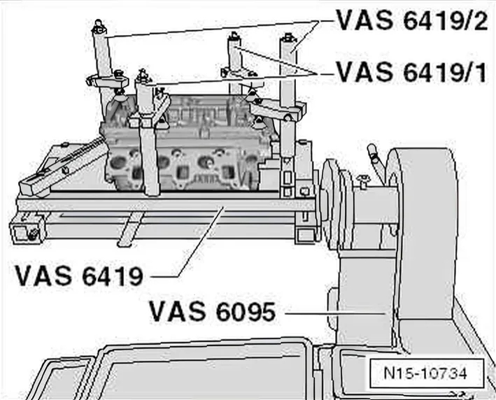
- Insert cylinder head tensioning device - VAS 6419- into engine and gearbox support - VAS 6095-.
- Tension cylinder head on cylinder head tensioning device as shown in the operating instructions.
Operating instructions for the cylinder head tensioning device - VAS 6419- are enclosed with unit.
- Connect cylinder head tensioning device to compressed air.
- Use lever -arrow- to slide air cushion under combustion chamber from which valve stem seal is to be removed.
- Allow compressed air to flow into air cushion until it lies against valve disc.
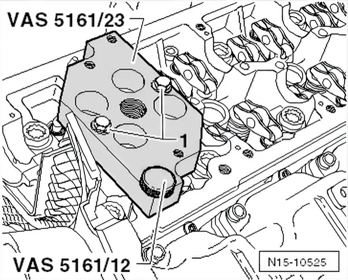
- Place guide plate -VAS 5161/23- onto cylinder head.
- Tighten guide plate on intake manifold side by hand using knurled screw -VAS 5161/12- and 2 M6x30 bolts until it makes contact.
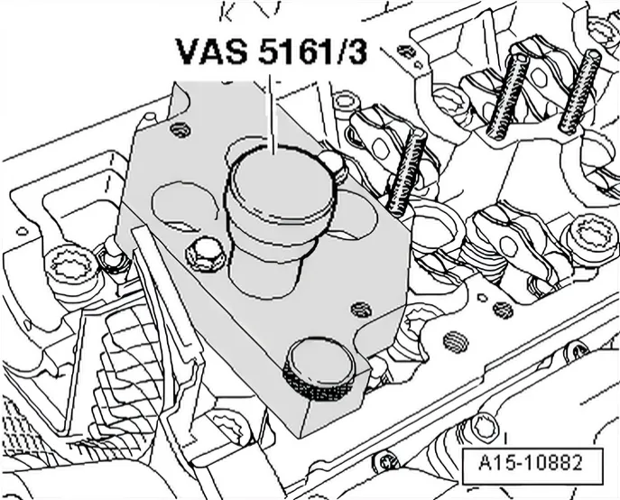
- Insert drift -VAS 5161/3- into guide plate and use a plastic hammer to knock loose the firmly seated valve cotters.
- Screw toothed piece -VAS 5161/6- with hooking fork - VAS 5161/5- into guide plate.
- Push sleeve -VAS 5161/23-1- onto assembly cartridge - VAS 5161/8-.
- Attach pressure fork -VAS 5161/2- to toothed piece and press assembly cartridge down.
- At the same time, turn knurled screw of assembly cartridge clockwise until tips engage in valve cotters.
- Move knurled screw back and forth to press apart valve cotters and capture them in assembly cartridge.
- Release pressure fork.
- Remove assembly cartridge with knurled spacer ring.
- Remove valve spring and valve spring plate.
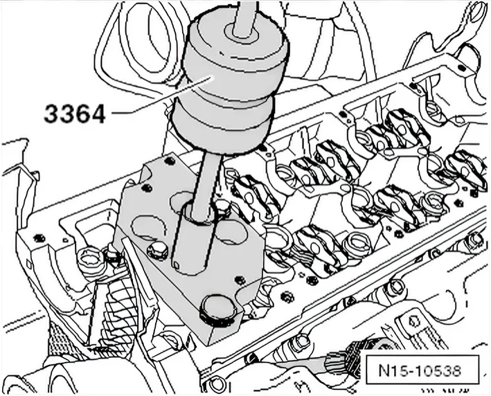
- Pull off valve stem seal using valve stem seal puller - 3364-.
- Lightly oil sealing lip of valve stem oil seal and valve stem.
- Carefully push valve stem oil seal on valve stem -A-.
- Carefully press valve stem oil seal onto valve guide using valve stem seal fitting tool - 3365-.
If the valve cotters have been removed from the assembly cartridge, they must first be inserted into the valve insertion device - VAS 5161/18-.
- Larger diameter of valve cotters faces upwards.
- Insert valve spring and valve spring plate.
- Press assembly cartridge onto valve insertion device from above and pick up valve cotters.
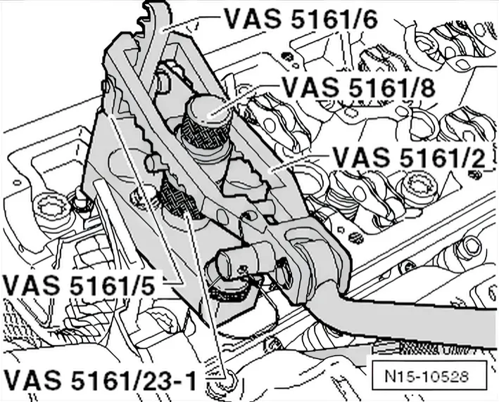
- Insert assembly cartridge into guide plate -VAS 5161/23- again.
- Press pressure fork downwards and pull knurled screw upwards, turning it clockwise and anticlockwise. This inserts the valve cotters.
- Reduce pressure on pressure fork whilst pulling on knurled screw.
- Repeat procedure on each valve.
Assembling
Installation is carried out in the reverse order; note the following:
- Ensure that all roller rocker fingers contact valve stem ends correctly and are clipped into relevant hydraulic compensation elements.
- Install camshafts ⇒ 3.5 Removing and installing camshafts.
3.4.6 Checking valves
- Check for scoring on valve stems and valve seat surfaces.
- Exchange valve if significant scoring can be seen.