
1.2 TDI CR engine (EA189) · Cylinder head, valve gear · Cylinder head
Removing and installing cylinder head
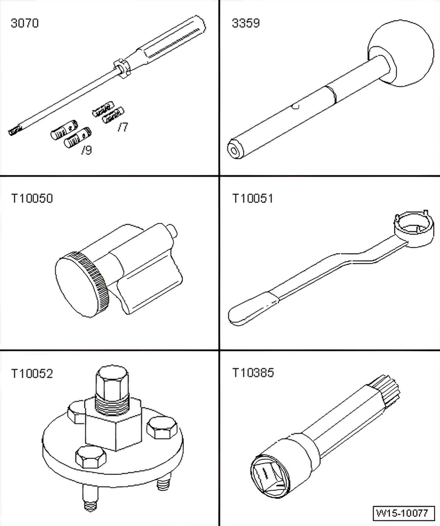
Special tools and workshop equipment required
- Guide pin - 3070-
- Diesel injection pump locking pin - 3359-
- Crankshaft stop - T10050-
- Counter-hold tool - T10051-
- Puller - T10052-
- Socket XZN 10 - T10385-
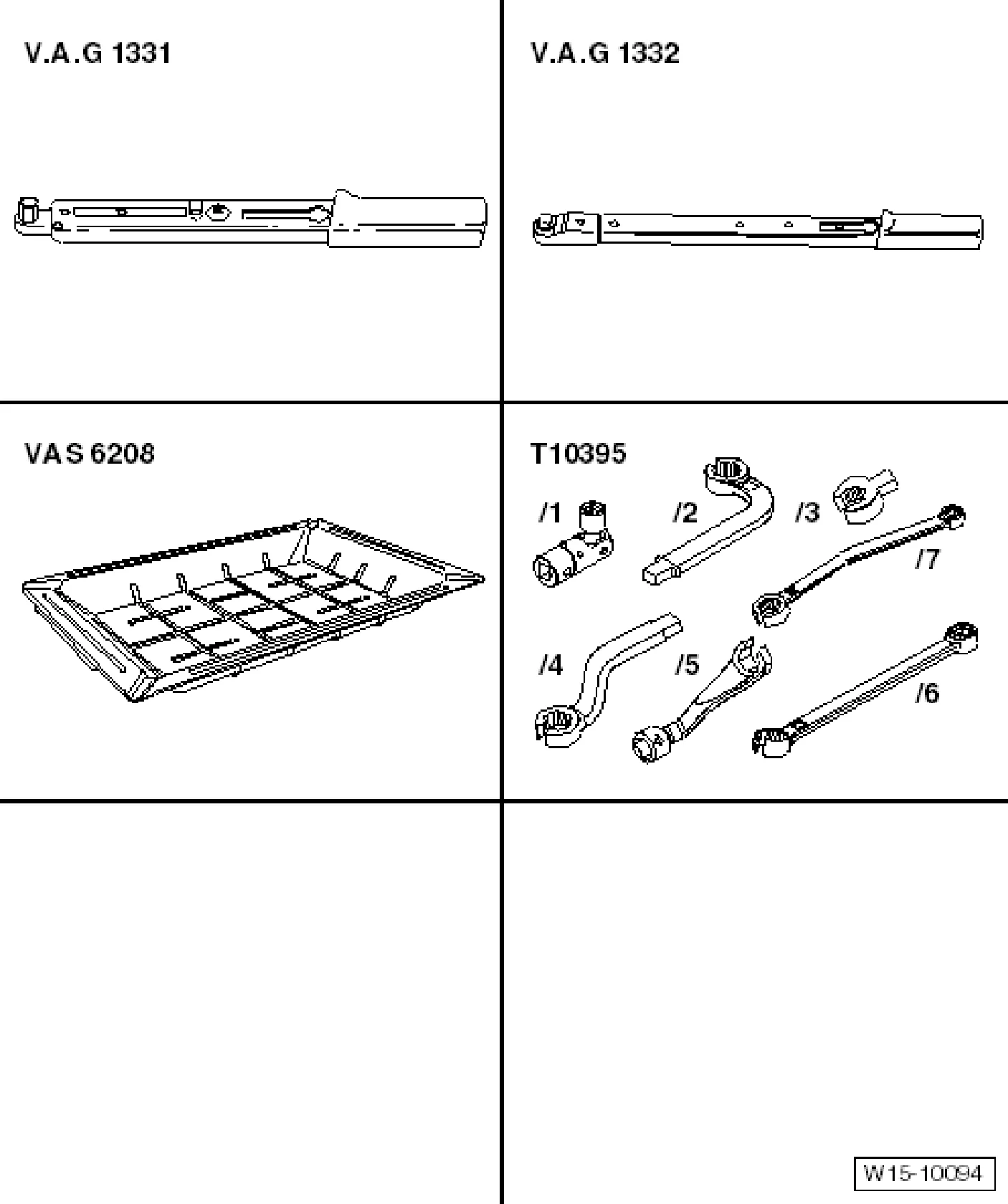
- Torque wrench - V.A.G 1331-
- Torque wrench - V.A.G 1332-
- Drip tray for workshop hoist - VAS 6208-
- Tool set - T100395-
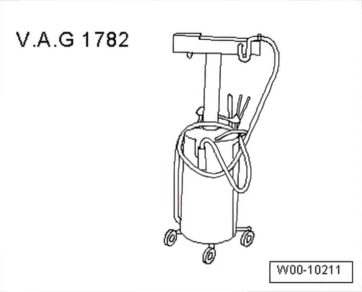
- Used oil collection and extraction unit - V.A.G 1782-
1.4.1 Removing
» Please carry out the following work sequence«
- Engine cover panel ⇒ 3 Engine cover panel.
- With ignition switched off, disconnect battery earth strap. ⇒ Electrical system; Rep. gr. 27; Disconnecting and reconnecting batteries.
- Remove wiper arms ⇒ Electrical system; Rep. gr. 92; Windscreen wiper system; Removing and installing wiper arms.
- Remove plenum chamber bulkhead ⇒ General body repairs; Rep. gr. 50; Body - front, plenum chamber bulkhead.
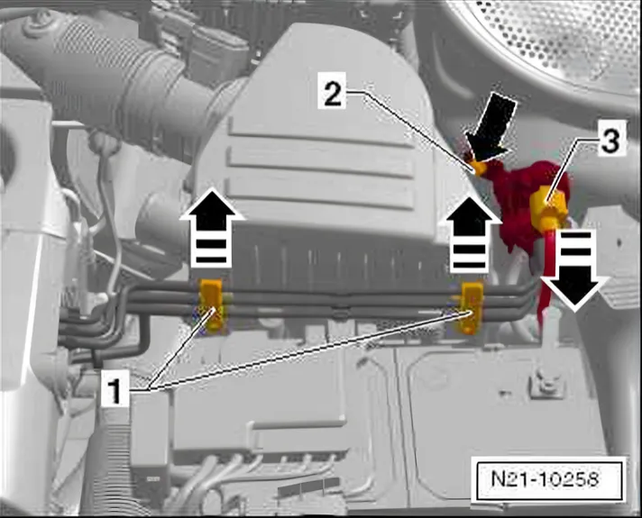
- Remove vacuum hoses with bracket -1- from air filter.
- Remove connector from charge pressure control solenoid valve - N75- -3-.
- Unbolt charge pressure control solenoid valve - N75- with bracket -2-.
- Place charge pressure control solenoid valve - N75- with vacuum lines on engine.
- Remove charge air pipe »hot« side ⇒ 2.3 Fitting charge air system hose connections.
- Remove charge air pipe »cold« side ⇒ 2.3.2 Removing and installing charge air pipe »hot« side.
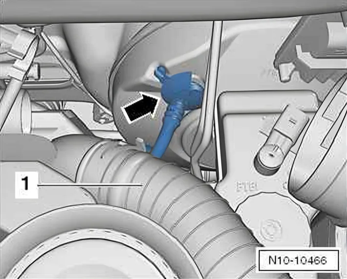
- Detach vacuum line -arrow- on brake servo.
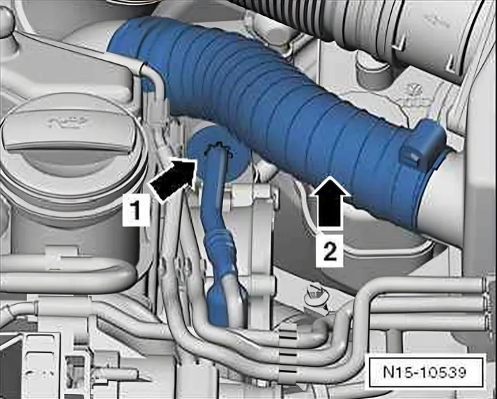
Pre-heater line -arrow 2- is not necessarily installed.
- Drain coolant ⇒ 19 – Cooling.
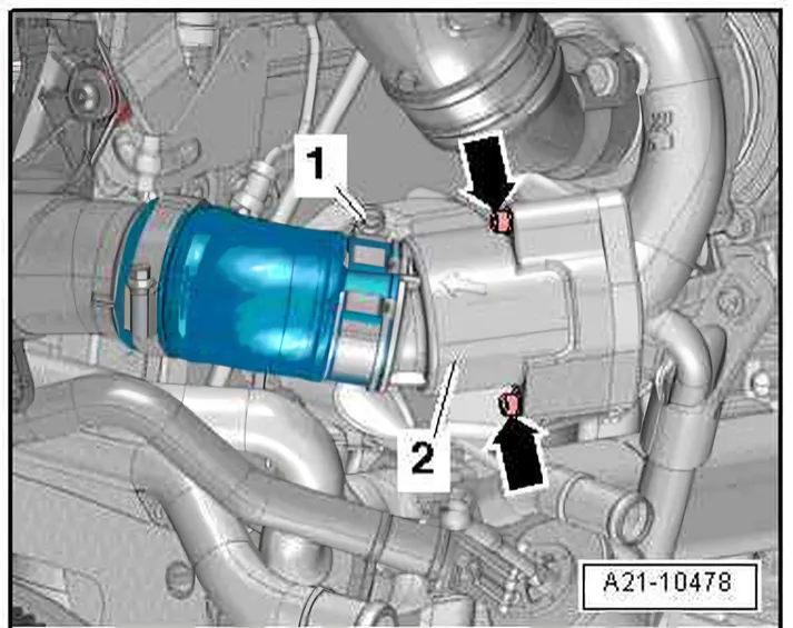
- Unscrew bolts -arrows- and remove pulsation damper -2-.
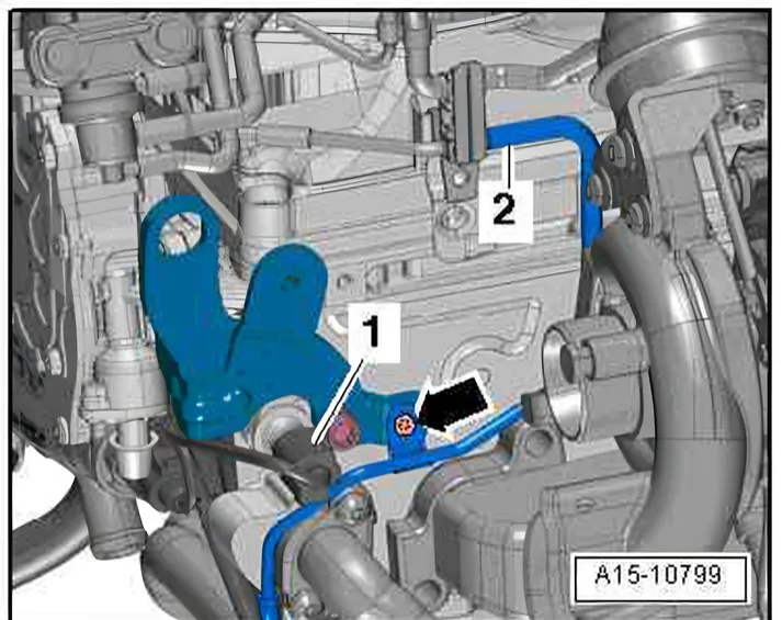
- Separate electrical connector -1- on oil pressure switch - F1-.
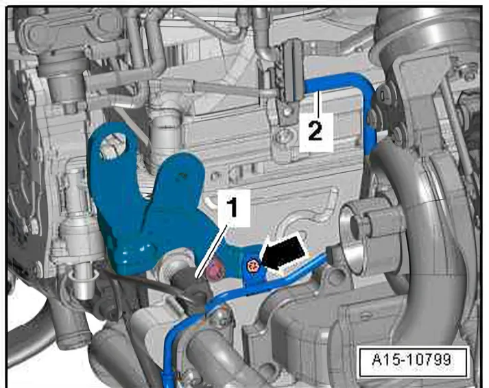
- Pull off vacuum hose -2-, unscrew vacuum hose connection -arrow-.
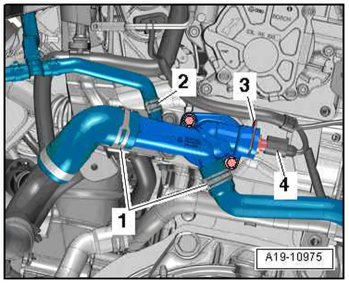
- Disconnect electrical connector -4- at coolant temperature sender - G62-.
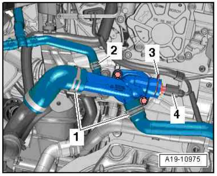
- Remove coolant hoses from connections, loosen hose clips -1- and -2- for this.
- Disconnect connectors -1…4-.
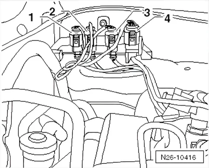
- -1- Exhaust gas temperature sender 1 - G235-
- -2- Exhaust gas temperature sender 3 - G495-
- -3- Exhaust gas temperature sender 4 - G648-
- -4- lambda probe - G39-
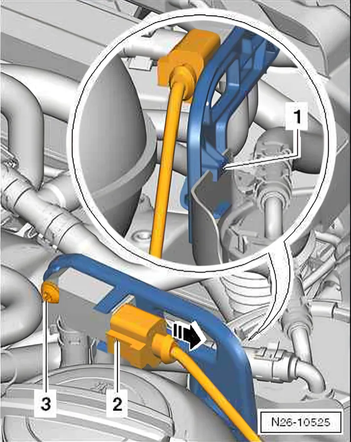
- Disconnect electrical connector -2- at pressure differential sender - G505-.
- Unscrew bolt -3- from pressure differential sender - G505- bracket.
- Lay pressure differential sender - G505- with lines down to rear.
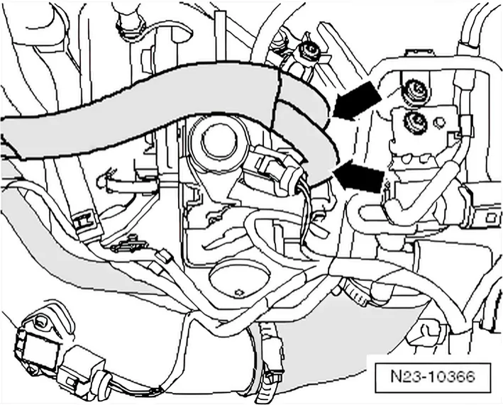
- Remove fuel supply line and return line -arrows- at high-pressure pump.
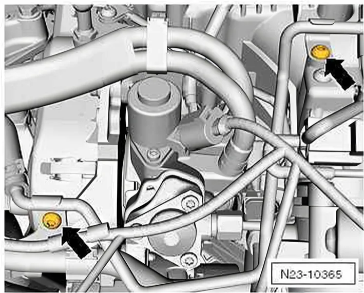
- Unscrew coolant return line bolts -arrows-, lay coolant return line aside.
- Remove cylinder head cover ⇒ 1.1 Assembly overview - cylinder head cover.
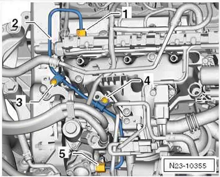
- Detach high-pressure line -2- between fuel rail and high-pressure pump.
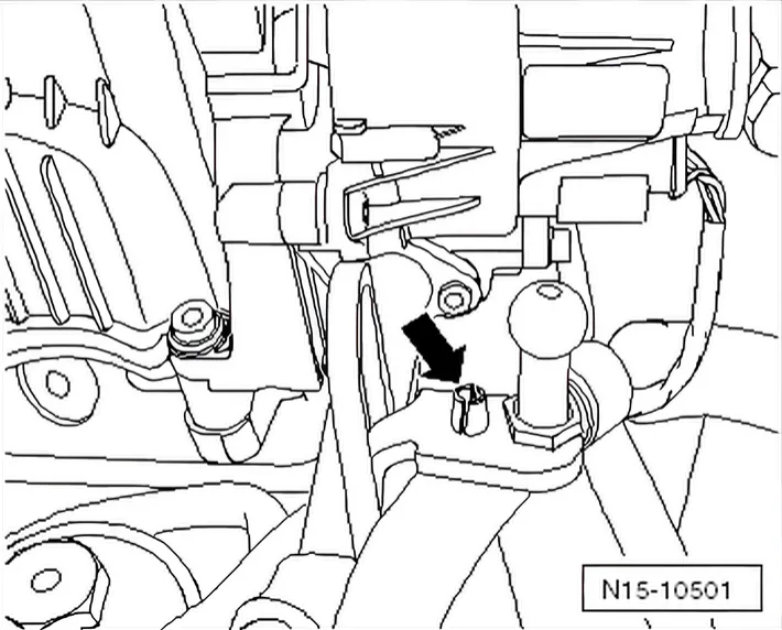
- Unclip engine pre-wiring harness from bracket -arrow-.
- Separate all remaining connectors to engine.
- Lay engine pre-wiring harness to one side.
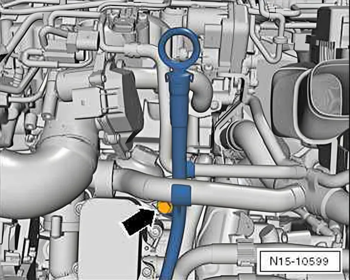
- Unscrew bolt from oil dipstick connection -arrow-.
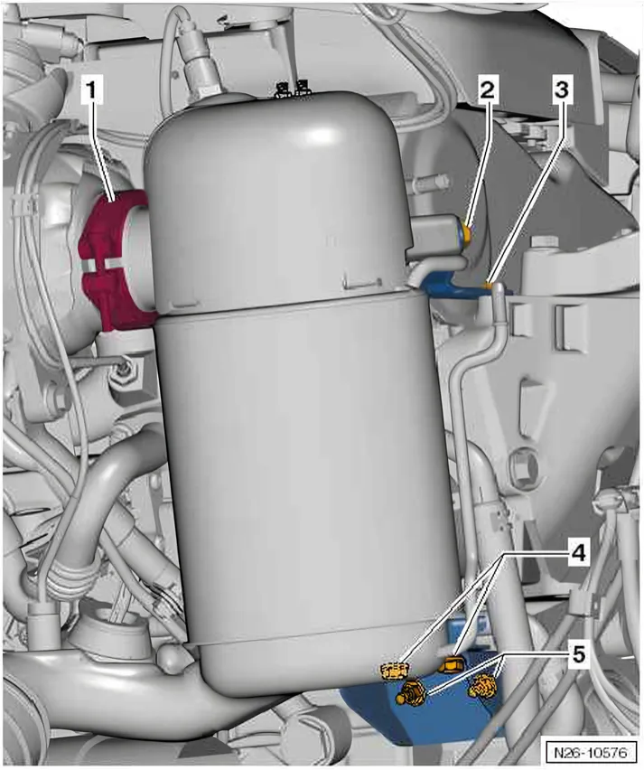
Loosen particulate filter.
| 1) | Remove securing clamp between particulate filter and turbocharger |
|---|---|
| 2) | Unscrew bolts and nuts -2 … 3- |
| 3) | Loosen bolt -4- |
| 4) | Unscrew nuts -5- |
- Secure particulate filter to plenum chamber bulkhead.

- Remove connecting pipes -A- for exhaust gas recirculation.
- Install oil supply line and turbocharger support ⇒ 4.1.1 Assembly overview - oil supply line and oil return (turbocharger support).
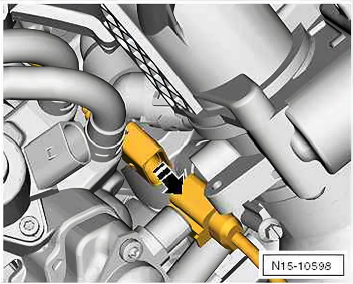
- Separate connector for Hall sender - G40- -arrow-.
- Removing toothed belt from camshaft and high-pressure pump ⇒ 2 Toothed belt drive.
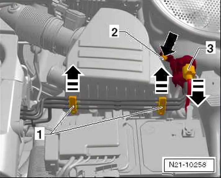
- Remove vacuum hoses complete with bracket -1- upwards from air filter.
- Remove connector from charge pressure control solenoid valve - N75- -3-.
- Unbolt charge pressure control solenoid valve - N75- with bracket -2-.
- Place charge pressure control solenoid valve - N75- with vacuum lines on engine.
- Remove charge air pipe »hot« side ⇒ 2.3 Fitting charge air system hose connections.
- Remove charge air pipe »cold« side ⇒ 2.3.2 Removing and installing charge air pipe »hot« side.
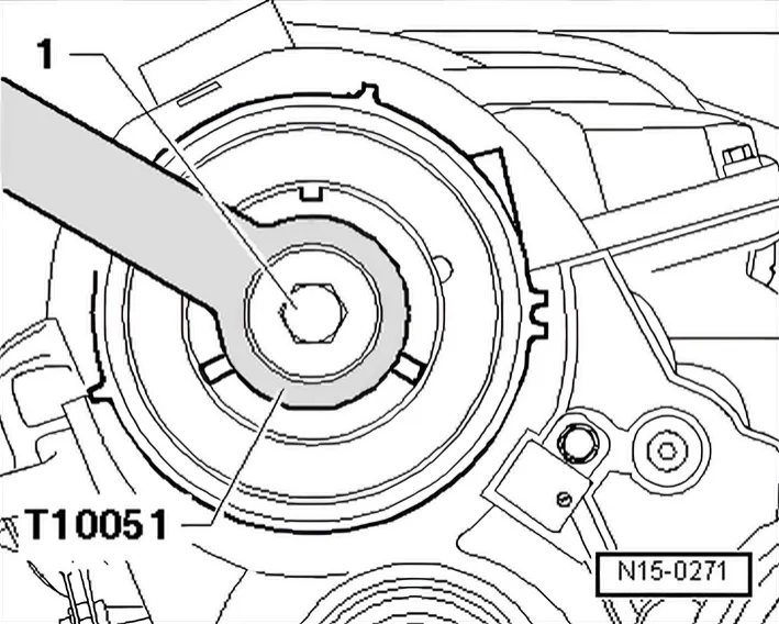
- Counterhold hub with counterhold - T10051-, loosen hub securing bolt -1-.
- Unscrew hub securing bolt approx. 2 turns.
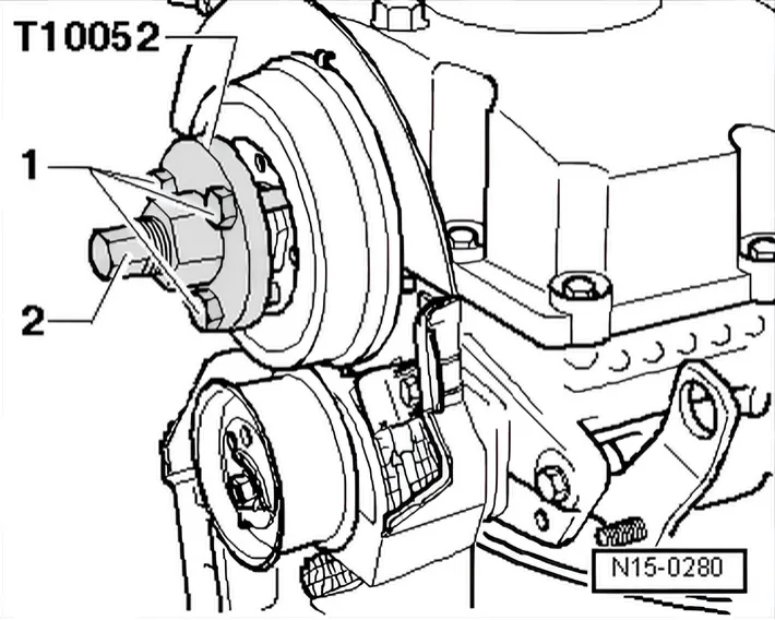
- Position puller - T10052- and align with holes in hub.
- Tighten securing bolts -1-.
- Apply tension to hub by evenly tightening puller -2- until hub separates from taper of camshaft.
- Remove hub from taper of camshaft.
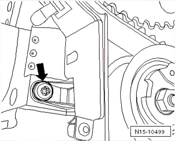
- Unscrew securing bolt -arrow- from toothed belt guard.
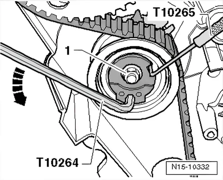
- Unscrew nut -1- for tensioning roller.
- Unscrew cylinder head bolts.
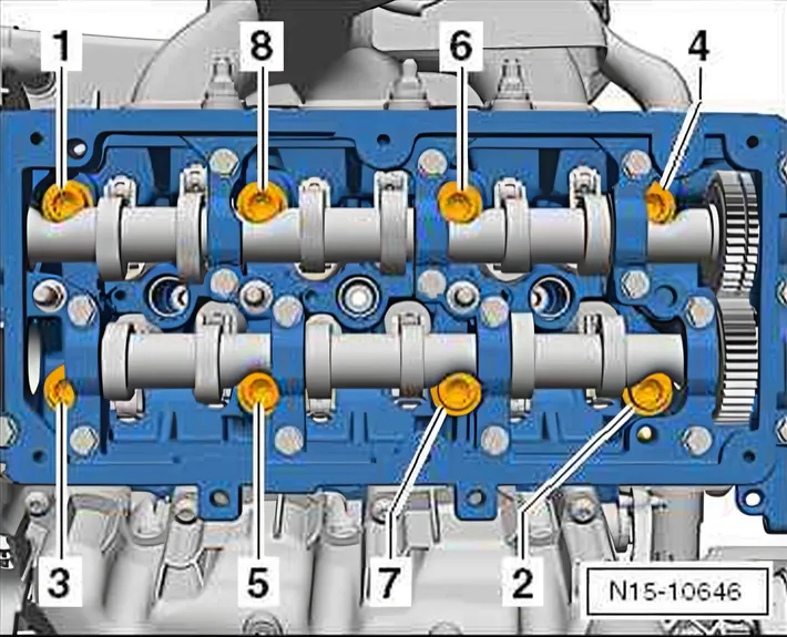
- Maintain sequence when loosening cylinder head bolts.
- First raise cylinder head on gearbox side and thread out of toothed belt guard. Make sure that toothed belt tensioner does not fall down.
1.4.2 Installing
Install in reverse order, noting the following:
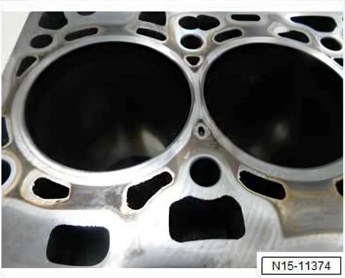
- Only remove sealant residue from cylinder head and cylinder block using scraper - VAS 852 005- or a commercially available ceramic glass scraper.
- The sealing surfaces must not be damaged.
- There must be no oil or coolant in the bolt pockets.
- Do not remove new cylinder head gasket from packaging until it is ready to be fitted.
- If a new cylinder head is installed, contact surfaces between roller rocker fingers and running surface of cam must be oiled.
- Handle the cylinder head gasket very carefully to prevent damage to the silicone coating or the indented area of the gasket.
- Turn the crankshaft carefully at least 2 rotations to ensure that none of the valves make contact when the starter is operated.
- When the cylinder head or cylinder head gasket is renewed, the entire coolant and the engine oil must be changed.
- Remove any loose remains using a lint-free cloth.
- Before fitting cylinder head, remove crankshaft stop - T10050-, and turn crankshaft in opposite direction of engine rotation until all pistons are nearly uniformly below TDC.
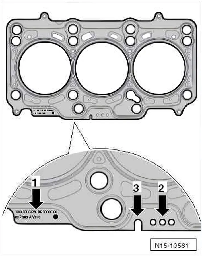
- Note cylinder head gasket identification:
- 1 Part number
- 2 Holes
- 3 Ignore
- Cylinder head gasket must lie with identification facing upwards.
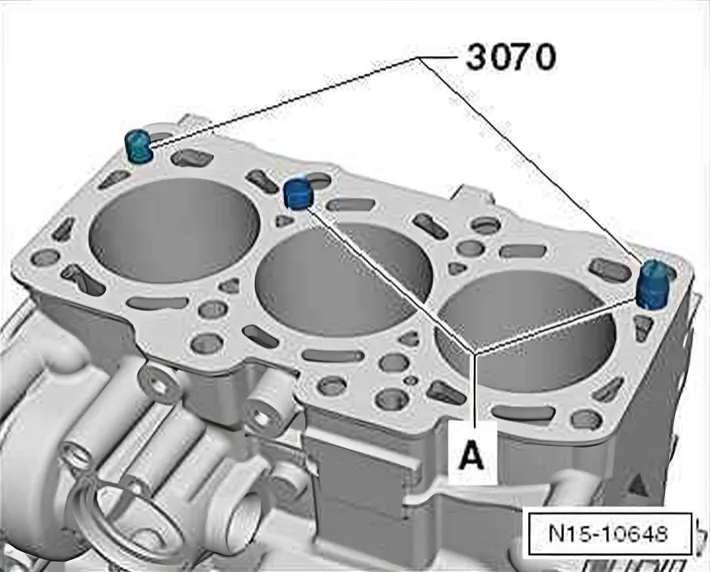
- To centre, screw guide pins -3070/9- into outer threaded holes on intake side.
- Fit cylinder head.
- Insert 8 cylinder head bolts and screw in by hand until contact is made.
- Unscrew guide pins -3070/9- through bolt holes in cylinder head and screw remaining cylinder head bolts by hand until contact is made.
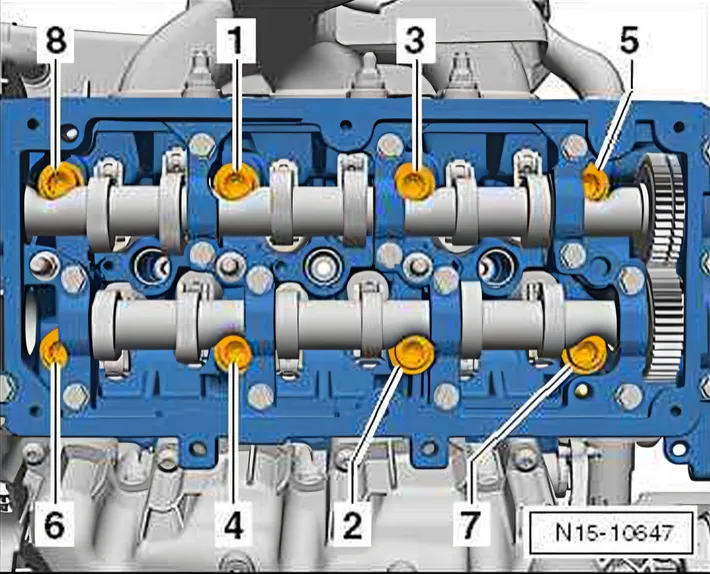
- Tighten cylinder head in 4 stages in sequence shown as follows:
- 1 Tighten initially with torque wrench:
Stage I = 30 Nm
Step II = 50 Nm
- 2 Turn further with rigid spanner:
Stage III = turn 90° further.
Stage IV = turn 90° further.
- Secure rear toothed belt guard on cylinder head.
- Install hub and camshaft sprocket.
- Lock camshaft and high-pressure pump with diesel injection pump locking pin - 3359-.
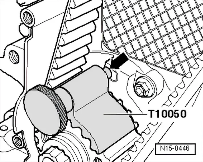
- Turn crankshaft in direction of engine rotation to TDC of No. 1 cylinder, and lock crankshaft using crankshaft stop - T10050-.
Continue installation in reverse order of removal. During this procedure, observe the following:
- Install toothed belt again ⇒ 2.2.1 Removing.
- Install cylinder head cover ⇒ 1.1 Assembly overview - cylinder head cover.
- Install oil supply line and turbocharger support ⇒ 4.1.1 Assembly overview - oil supply line and oil return (turbocharger support).
- Install poly V-belt ⇒ 13 – Crankshaft group.
- Add coolant ⇒ 1.3.1 Draining.
- Top up engine oil ⇒ 1.3 Removing and installing sump.
After any work on the fuel system
Connect vehicle diagnostic tester.
Perform function “Fuel pump actuation (Filling/bleeding fuel system)” in “Guided Functions” ⇒ 1.3 Filling/bleeding fuel system.
- Carry out road test and read all event memories ⇒ 9 Engine control unit.