
1.2 TDI CR engine (EA189) · Cylinder head, valve gear · Valve gear
Valve gear – assembly overview and fastening
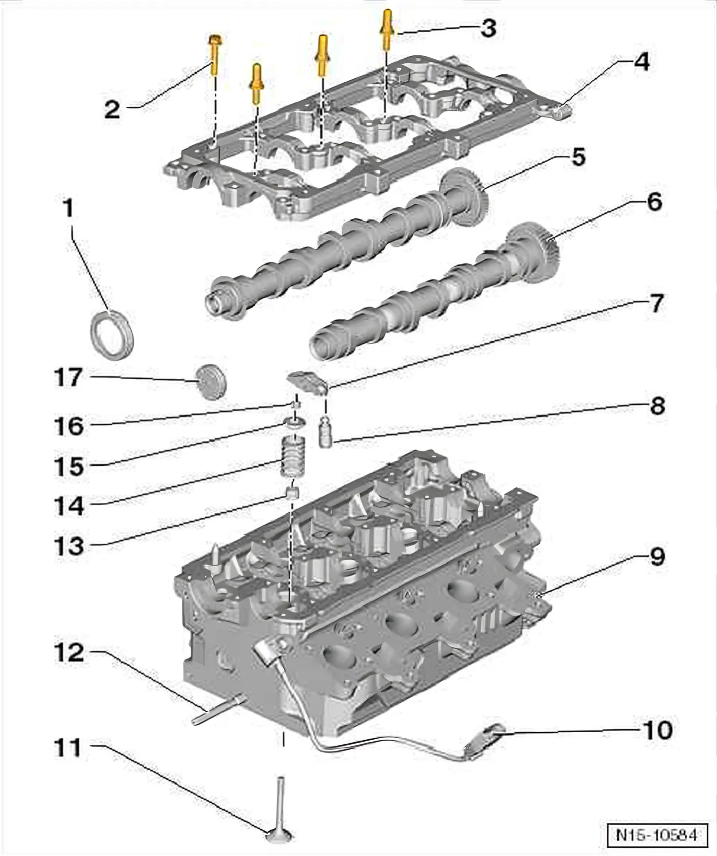
- 1 Seal
- Do not additionally oil or grease the oil seal sealing lip.
- Before installing, remove residual oil from camshaft journal using a clean cloth.
- To install, mask off groove on camshaft taper (e.g. using Sellotape)
- Removing and installing ⇒ 3.6 Checking hydraulic compensation elements
- 2 10 Nm
- 3 Guide pins
- 10 Nm
- 4 Bearing frame
- Observe sequence for loosing and tightening ⇒ 3.5 Removing and installing camshafts
- Seal with sealant as per ⇒ ETKA (Electronic
Parts Catalogue)
- 5 Exhaust camshaft
- 6 Inlet camshaft
- 7 Roller rocker fingers
- Mark installation position
- Do not interchange
- Check roller bearing for ease of movement.
- Oil cam contact surface before installing.
- Removing and installing ⇒ 3.4.3 Checking valve guides
- 8 Hydraulic compensation element
- Mark installation position
- Lubricate contact surfaces before installing.
- 9 Cylinder head
- See note ⇒ 1.2.3 Removing and installing injector seal in cylinder head cover.
- Removing and installing ⇒ 1.3 Assembly overview - cylinder head
- 10 Hall sender - G40- connector
- Removing and installing ⇒ 1.2 Removing and installing ceramic glow pin plugs; carrying out resistor test
- 11 Valve
- Do not rework. Only lapping in is permitted.
- Mark installation position for re-installation.
- Valve dimensions ⇒ 3.4 Inlet and exhaust valves
- Checking valve guides ⇒ 3.4 Inlet and exhaust valves
- 12 Stud
- 13 Valve stem seal
- 14 Valve springs
- 15 Valve spring plate
- 16 Valve cotter
- 17 Cap
- Renew
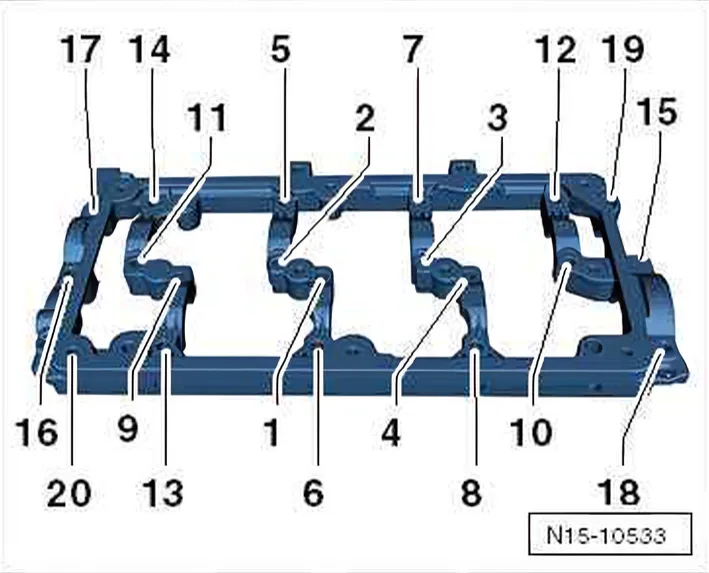
Retaining frame - specified torques and installation sequence
- Unscrew retaining frame securing bolts in sequence -20…1-.
- Tighten bolts in 2 stages in the sequence shown:
| Stage | Bolts | Specified torque |
|---|---|---|
| 1) | -1 … 20- | Screw in by hand as far as stop • The retaining frame must make contact with the cylinder head over the entire contact surface. |
| 2) | -1 … 20- | 10 Nm |