
1.2 TDI CR engine (EA189) · Cylinder head, valve gear · Valve gear
Removing and installing camshafts
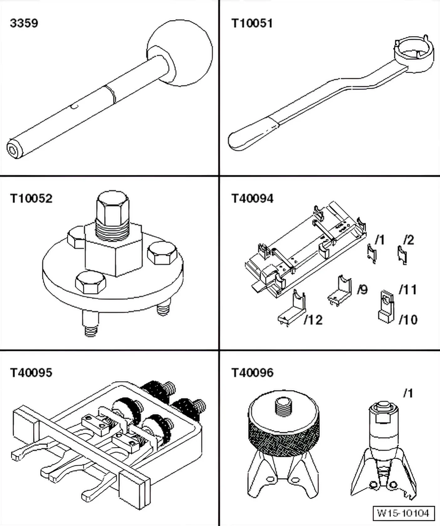
Special tools and workshop equipment required
- Diesel injection pump locking pin - 3359-
- Counter-hold tool - T10051-
- Puller - T10052-
- Camshaft fitting tool - T40094-
- Camshaft clamping tool - T40095-
- Camshaft fitting tool - T40096-
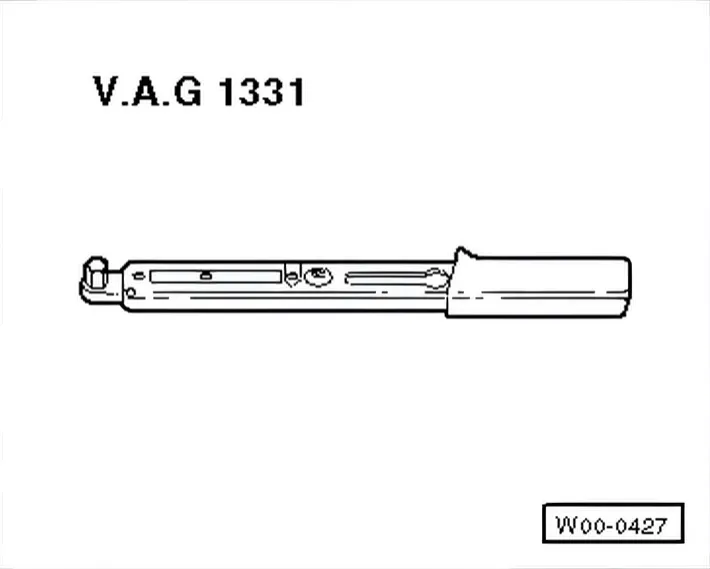
- Torque wrench - V.A.G 1331/-
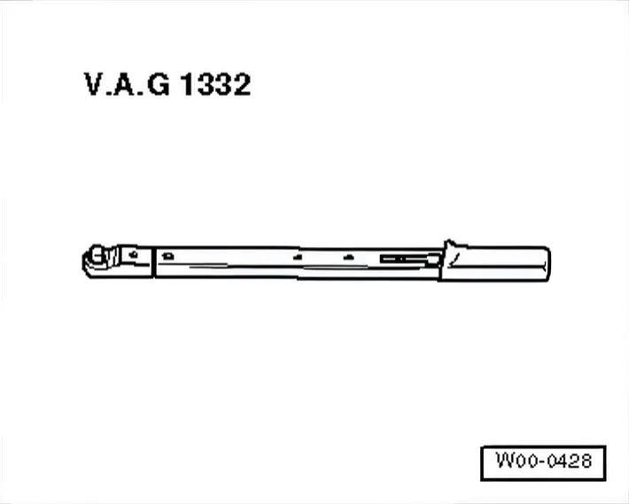
- Torque wrench - V.A.G 1332/-
- Sealant as per ⇒ ETKA (Electronic Parts Catalogue)
3.5.1 Removing
»Carry out the following work sequence«
- Remove cylinder head cover ⇒ 1.2.1 Removing cylinder head cover.
- Removed toothed belt from camshaft and high-pressure pump ⇒ 2.1.1 Removing and installing engine bracket.
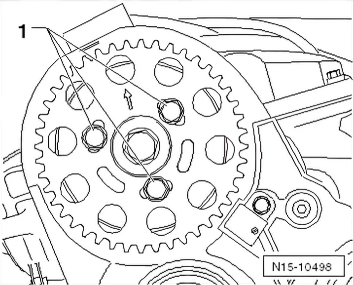
- Unscrew camshaft sprocket securing bolts -1-.
- Remove camshaft sprocket from hub.
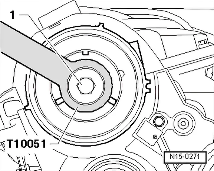
- Counterhold hub with counterhold - T10051- and loosen hub securing bolt -1-.
- Unscrew hub securing bolt approx. 2 turns.
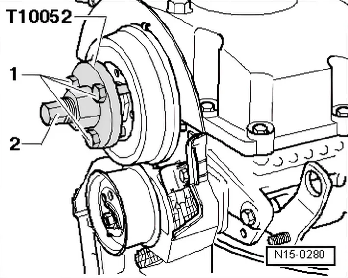
- Position puller - T10052- and align with hub holes.
- Tighten securing bolts -1-.
- Apply tension to hub by evenly tightening puller -2- until hub separates from taper of camshaft.
- Remove hub from camshaft taper.
- Remove vacuum pump ⇒ Item 4 (page 67).
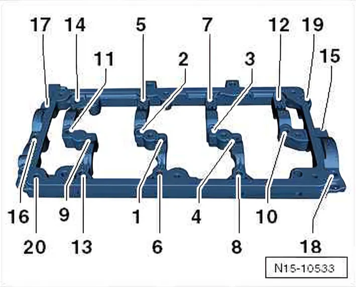
- Unscrew retaining frame securing bolts in sequence -20…1-.
- Remove retaining frame.
- Carefully remove camshafts.
3.5.2 Installing
- Remove sealant residue from cylinder block and retaining frame using, for example, a plastic rotary brush.
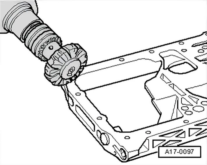
- Clean sealing surfaces. They must be oil and grease free.
- Oil running surfaces of camshafts.
Set up camshaft fitting tool - T40094- for camshafts as follows:
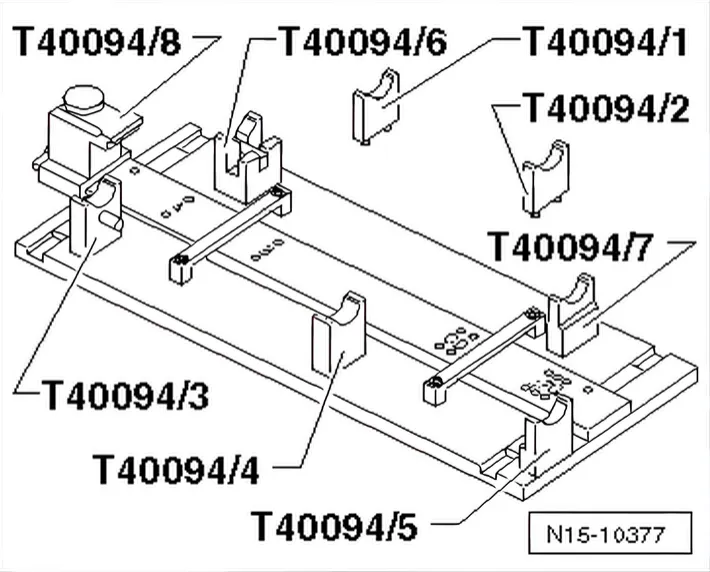
- Remove supports -T40094/3-, -T40094/4- and -T40094/5- from base plate. Threaded connection is accessible from below.
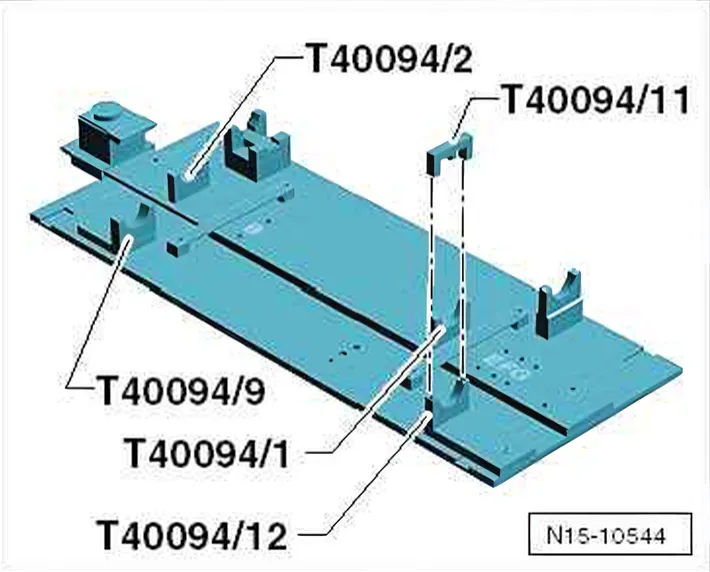
- Instead, position supports -T40094/9- and -T40094/12- on outer positions which have become free.
- Place support -T40094/2- in position “A”. Place support - T40094/1- in position “D”.
- First insert inlet camshaft as shown. Ensure that indentation -arrow- for cylinder head bolt faces »outwards«.
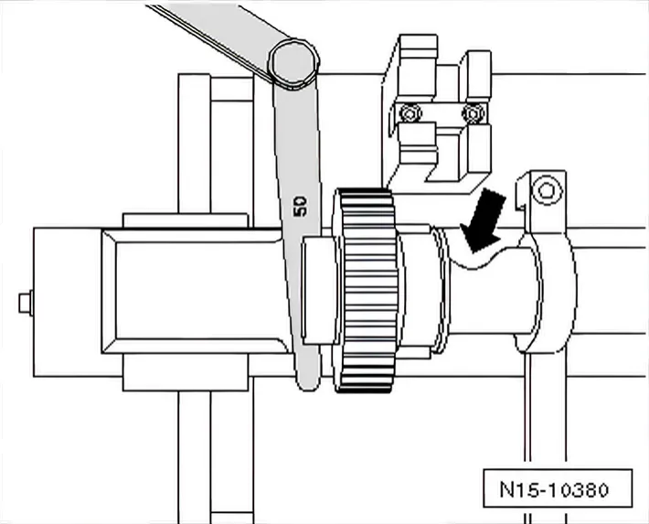
- Fit 0.50 mm feeler gauge. Push support -T40094/8- into inlet camshaft groove.
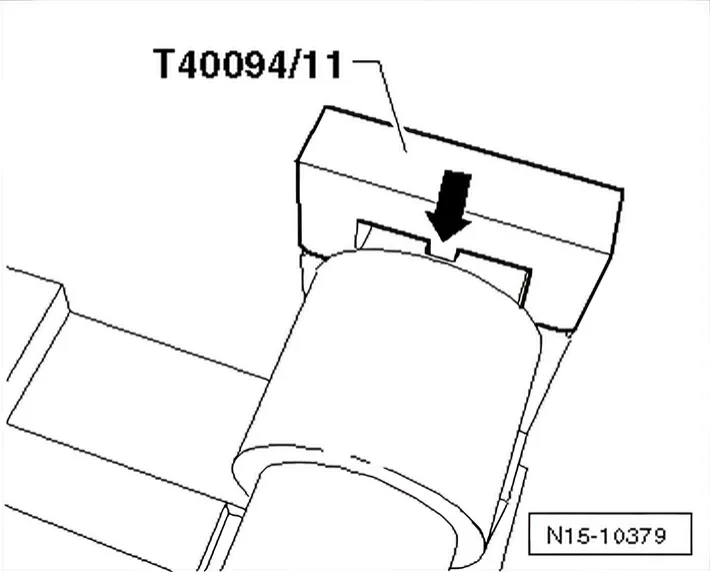
- Insert exhaust camshaft, lock via its groove -arrow- with -cover T40094/11-.
- Position clamping tool - T40096/1- on exhaust camshaft sprockets.
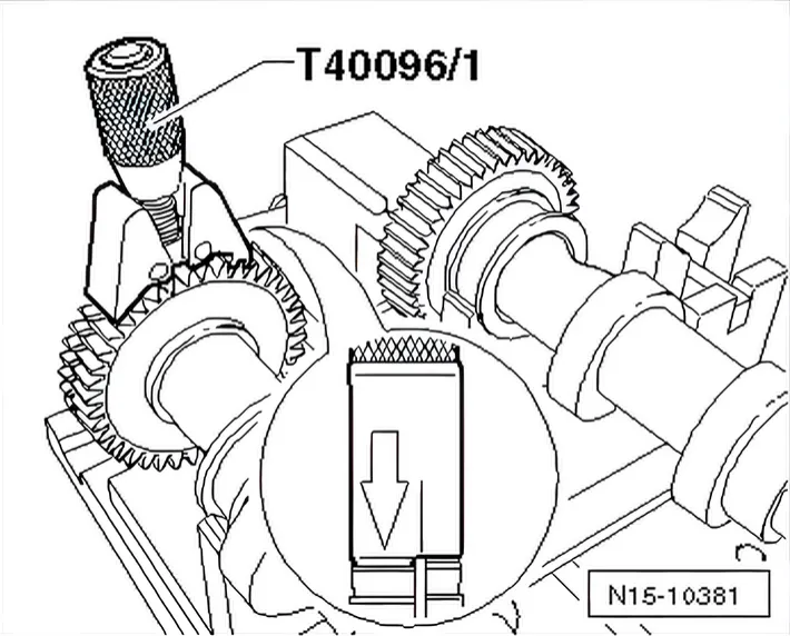
- Tighten clamping tool - T40096/1- using knurled wheel so that faces of gear teeth are in alignment. Use a 13 mm open-end spanner to assist if necessary.
- Slide exhaust camshaft towards inlet camshaft until teeth engage.
- Position retaining frame on camshafts.
- All camshaft bearings must be seated on the camshafts.
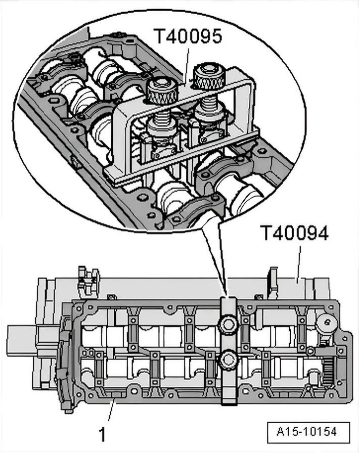
- Position camshaft fitting tool - T40095- as shown, thereby locking camshafts in retaining frame.
- Remove cover - T40094/11-.
- Pull support - T40094/8- out of inlet camshaft groove.
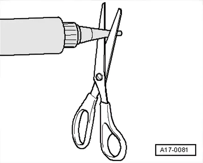
- Cut off nozzle on tube at front marking (∅ of nozzle approx. 2 mm).
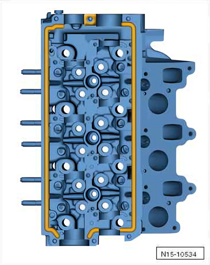
- Apply sealant beads (approx. 2 … 3 mm wide) -arrows- as shown in illustration on clean sealing surfaces of cylinder head.
- Install new cap ⇒ Item 17 (page 98) flush on cylinder head.
- Take camshafts out of camshaft fitting tool - T40095- together with retaining frame and camshaft fitting tool - T40094-.
- Carefully insert camshafts and retaining frame into cylinder head.
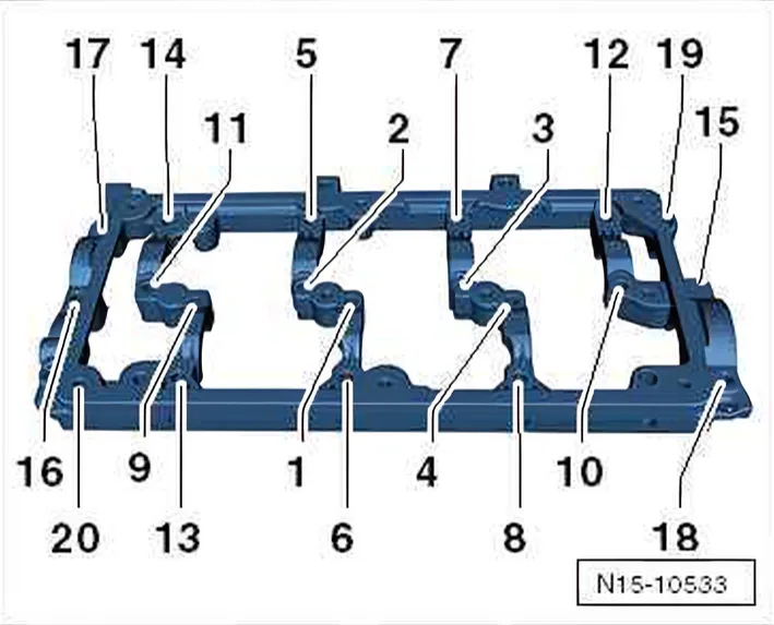
- First, tighten securing bolts of retaining frame hand-tight in sequence -1…20-.
- The retaining frame should make contact with the cylinder head over the complete surface.
- Tighten retaining frame bolts to final torque in the sequence -1 … 24-. Specified torque: 10 Nm.
- Remove camshaft fitting tool - T40095- and clamping tool - T40096/1-.
- Renew camshaft seal ⇒ 3.6 Checking hydraulic compensation elements.
Perform further installation in reverse order, paying attention to the following:
- Place hub back onto camshaft.
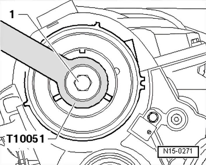
- Tighten hub securing bolt -1- to 100 Nm. Use counter-hold tool - T10051- to do this.
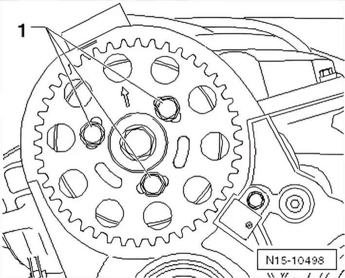
- Push camshaft sprocket onto hub.
- Hand tighten securing bolts -1- to camshaft sprocket so that there is no play.
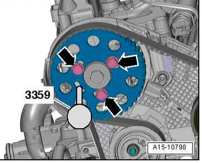
- Lock hub with locking pin - 3359-.
- Install toothed belt, adjust valve timing ⇒ 2.1.1 Removing and installing engine bracket.
- Install vacuum pump.
- Install cylinder head cover ⇒ 1.1 Assembly overview - cylinder head cover.
- Install fuel filter ⇒ Fuel supply; Rep. gr. 20.