
Brake systems · Brakes – hydraulics · Removing and installing brake booster
Removing and installing brake booster, right-hand drive vehicle
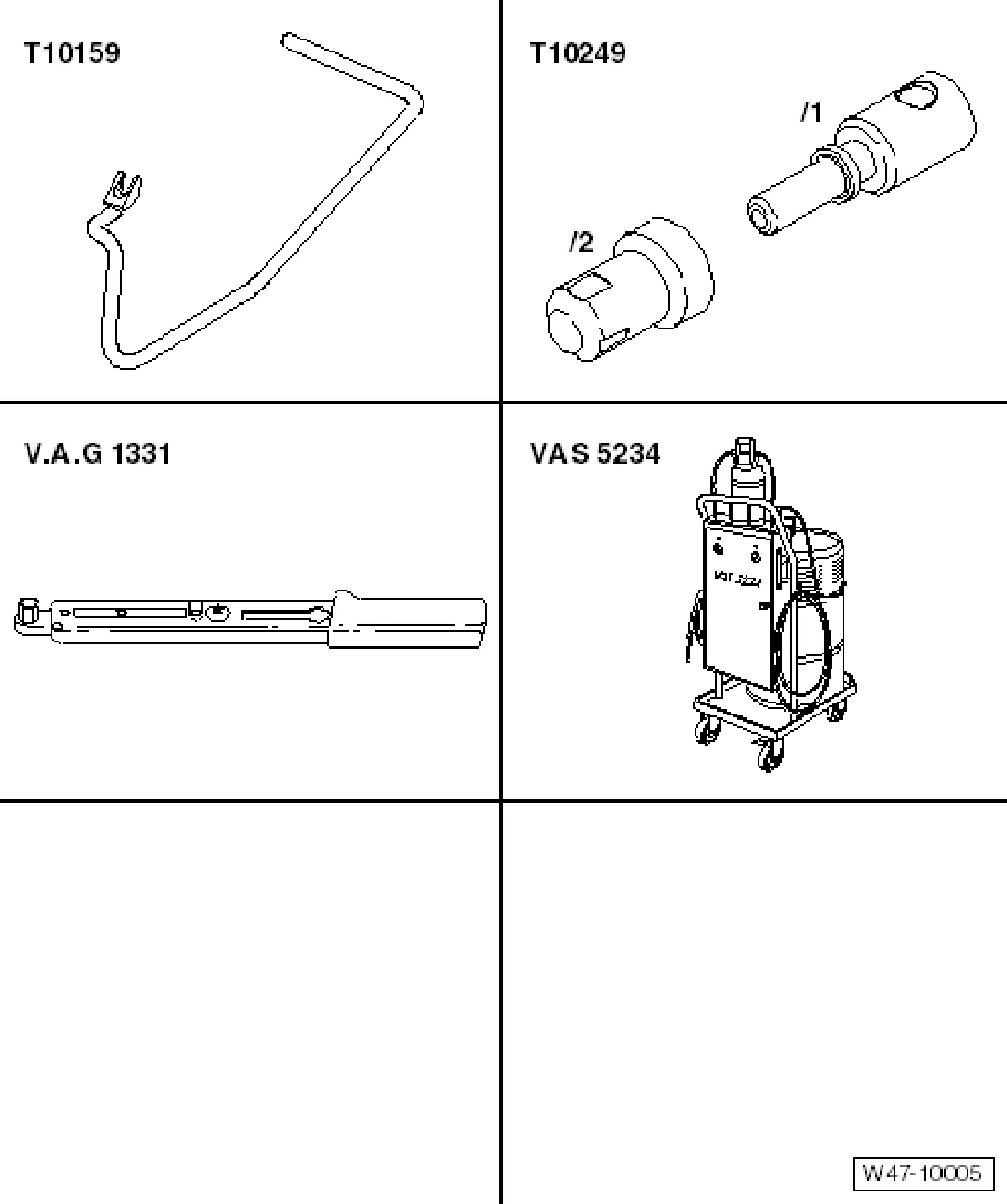
Special tools and workshop equipment required
- Release tool - T10159 A-
- Sealing tool - T10249-
- Torque wrench - V.A.G 1331-
- Brake filling and bleeding equipment - VAS 5234-
7.2.1 Removing
Vehicles with a 1.4 l 125 kW petrol engine
- Remove noise insulation ⇒ General body repairs, exterior; Rep. gr. 50; Front of body.
- Remove front right wheel housing ⇒ Body; Rep. gr. 66; Exterior equipment.
- Remove right drive shaft ⇒ Running gear, axles, steering; Rep. gr. 40; Front wheel suspension, drive shaft.
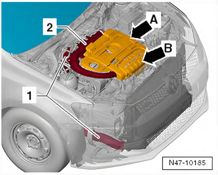
- Remove engine cover panel -arrow A- and heat shield -arrow B- ⇒ Rep. gr. 21; Charge air pressure system.
- Remove charge air pressure pipes -1- and -2- ⇒ Rep. gr. 21; Charge air pressure system.

- Remove air cowling -1- ⇒ Rep. gr. 19; Removing and installing parts of the cooling system.
- Remove noise insulation from compressor ⇒ Rep. gr. 21; Removing and installing compressor and place to one side.
- Remove throttle valve module - J338- ⇒ Rep. gr. 24; Removing and installing throttle valve module J338.
Vehicles with manual gearboxes
- Draw off as much brake fluid as possible from brake fluid reservoir using brake filling and bleeding equipment - VAS 5234- or extraction unit -V.A.G 1869/4-.
- Place sufficient lint-free cloths in area of engine.
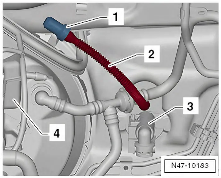
- Pull return hose -2- for clutch sender cylinder -3- off brake fluid reservoir -4-.
- Seal return hose -2- for clutch sender cylinder -3- with sealing tool - T10249- -1-.
- Tie return hose -2- in place above.
Continuation for all vehicles
- Detach brake booster from brake pedal ⇒ 5.2.1 Separating brake pedal from brake booster.
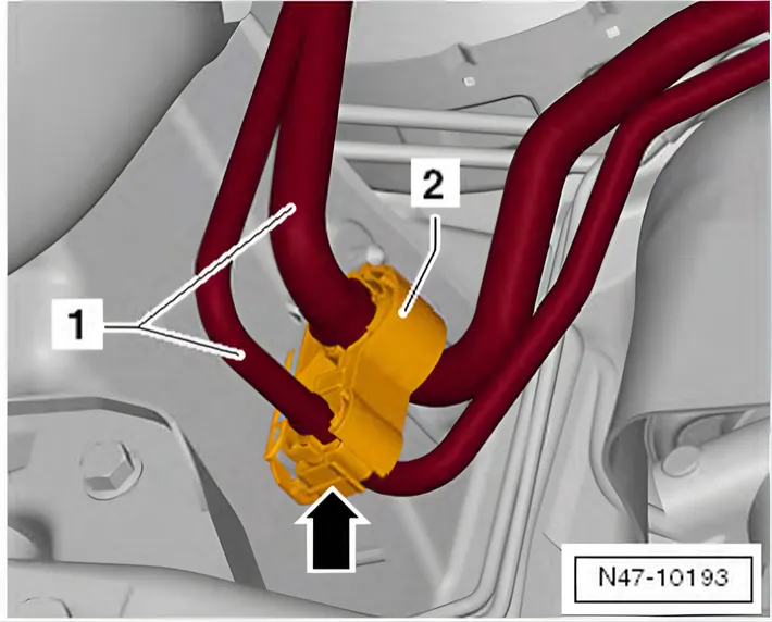
- Open holder -2- carefully at the locking lug -arrow-.
- Unclip coolant line -1-.

- Detach fuel lines -arrows- at connecting point in engine compartment on right.
- Place the fuel lines to one side.
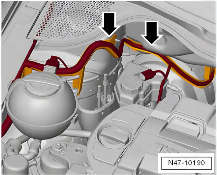
- Unclip wiring harness from holders -arrow-.

- Release connector -2- and pull off.
- Undo screws -3-.
- Place coolant expansion tank -1- to one side.
- Draw off as much brake fluid as possible from brake fluid reservoir using brake filling and bleeding equipment - VAS 5234-.
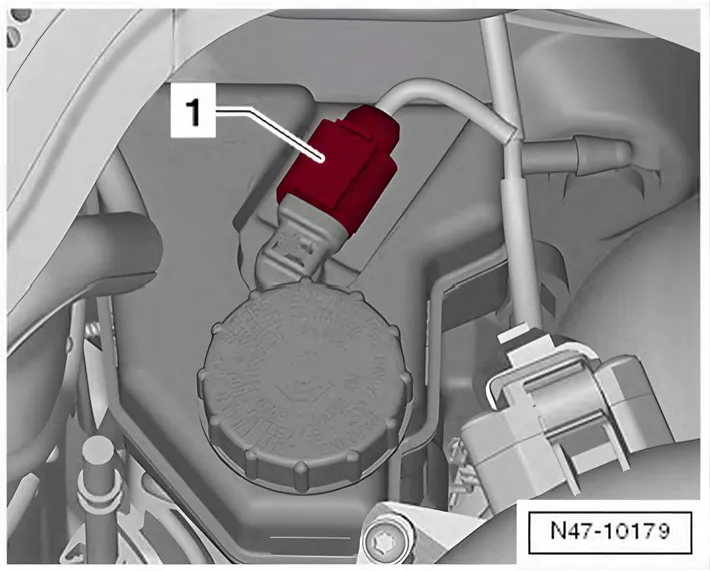
- Place sufficient lint-free cloths in area of engine.
- Release and pull connector -1- off brake fluid level warning contact - F34-.
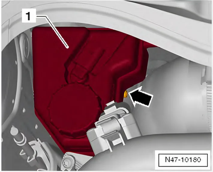
- Unscrew bolt -arrows- from brake fluid reservoir -1-.
- Carefully pull brake fluid reservoir out of sealing plugs of brake master cylinder.
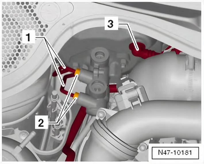
- Mark and unscrew brake lines -1- from brake master cylinder -2-.
- Seal brake lines with sealing plugs - 1H0 698 311 A-.
- Pull vacuum line -3- out of brake booster.

Vehicles with petrol engine and dual clutch gearbox
- Release connector -2- at brake booster pressure sensor - G294- -1- and pull connector off.
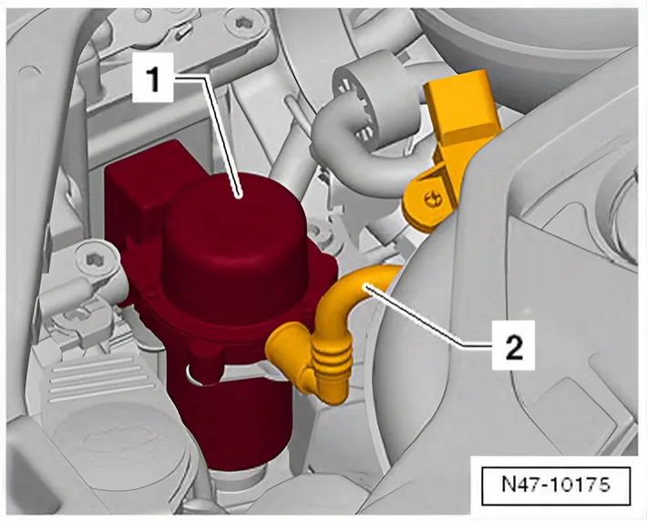
- Pull vacuum hose -2- off vacuum pump for brakes - V192- -1- and place to one side.
Continuation for all vehicles
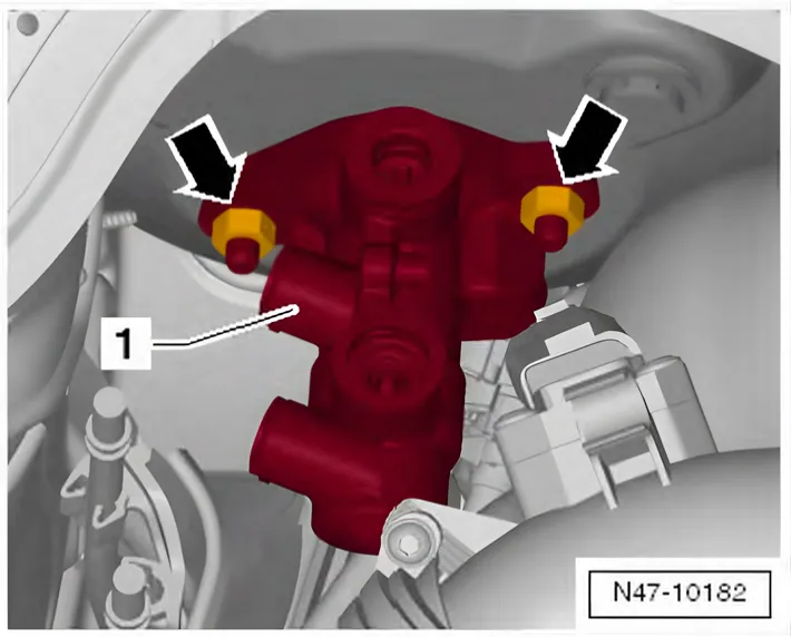
- Unscrew nuts -arrows- from brake master cylinder -1-.
- Release connector of brake light switch - F- and pull it off.
- Carefully remove brake master cylinder together with brake light switch - F- from brake booster.
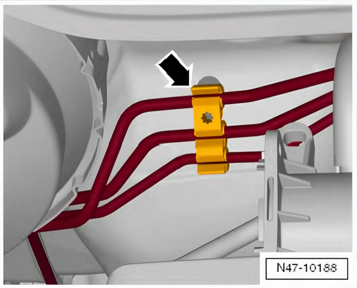
- Unclip brake hoses from bracket -arrow-.

- Remove nuts -arrows-.
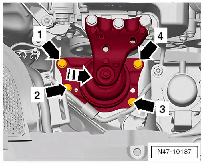
- Remove bolts -1- to -4- of engine mounting.
- Pull engine 3.5 cm forwards in -direction of arrow- by the engine mounting.
- Carefully remove brake booster from the vehicle.
7.2.2 Installing
Install in reverse order. Note the following points:
- Carefully insert brake booster and tighten nuts.
- When assembling brake master cylinder with brake booster, make sure plunger rod is properly positioned in brake master cylinder.
Coat sealing plugs with brake fluid before pressing brake fluid reservoir into brake master cylinder.
- Clip brake pedal to brake booster ⇒ 5.2.2 Clipping brake pedal to brake booster.
- Bleed brake system ⇒ 4 Bleeding brake system.
Specified torque
| Component | Specified torque |
|---|---|
| Brake booster to pedal cluster and plenum chamber bulkhead ♦Use new nuts | 25 Nm |
| Brake master cylinder to brake booster ♦Use new nuts | 25 Nm |
| Brake lines to brake master cylinder | 14 Nm |
| Brake fluid reservoir to brake master cylinder | 4 Nm |
| Coolant expansion tank to body | 5 Nm |