
Brake systems · Brakes – hydraulics · Assembly overview – brake booster/brake master cylinder
Brake booster/brake master cylinder (right-hand drive vehicle) – assembly overview and fastening
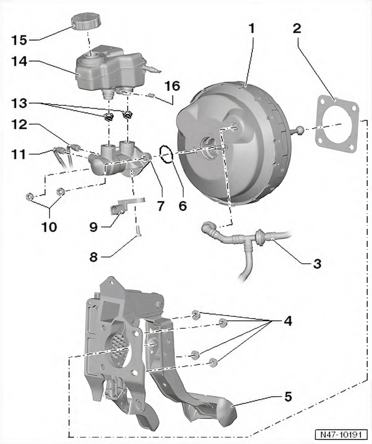
- 1 Brake booster
- In the case of petrol engines, the required vacuum is taken from the intake manifold.
- In the case of petrol engines with a dual clutch gearbox, the necessary vacuum is generated by the vacuum pump for brakes - V192-.
- Diesel engines are fitted with a vacuum pump to create the required vacuum.
- Checking function
- With engine switched off, depress brake pedal firmly several times (to exhaust vacuum in unit).
- Now step on and hold brake pedal with medium pressure and start engine. If the brake booster is functioning properly, the brake pedal will be felt to go down as the servo takes effect.
- Replace completely in the event of a fault (before doing so, check brake booster vacuum system) ⇒ 5.4 Checking brake booster vacuum system
- Non-return valve (in vacuum hose) functional check ⇒ 5.5 Checking non-return valve.
- Separating from brake pedal ⇒ 5.2.1 Separating brake pedal from brake booster
- Removing and installing ⇒ 7.2 Removing and installing brake booster, right-hand drive vehicle.
- 2 Seal
- For brake booster.
- 3 Vacuum line
- Allocation ⇒ Electronic parts catalogue “ETKA”
- 4 Self-locking hexagon nut
- 25 Nm
- Qty. 4
- Always renew after removing.
- 5 Pedal cluster
- Removing and installing ⇒ 5.2 Assembly overview - brake pedal, right-hand drive.
- 6 Sealing ring
- Renew.
- 7 Brake master cylinder
- Cannot be repaired. If faulty, renew as a complete unit.
- Removing and installing ⇒ 6.2 Removing and installing brake master cylinder, right-hand drive vehicle.
- 8 Bolt
- 7 Nm
- 9 Brake light switch - F-
- Including brake pedal switch - F47-.
- Removing and installing ⇒ 5.9 Removing and installing brake light switch - F-, right-hand drive.
- 10 Nut
- 25 Nm
- 11 Brake line
- ABS hydraulic unit - N55- to brake master cylinder/secondary piston circuit
- Marking on ABS hydraulic unit - N55- -HZ2-
- With thread M12 x 1
- 12 Brake line
- From primary piston circuit of brake master cylinder to ABS hydraulic unit - N55-.
- Marking on ABS hydraulic unit - N55- -HZ1-
- With thread M12 x 1
- 13 Sealing plug
- Moisten with brake fluid and press into brake master cylinder.
- 14 Brake fluid reservoir
- With brake fluid level warning contact - F34-
- 15 Cap
- 16 Bolt
- 4 Nm